EP0287524A2 - Dynamische Steuerung einer Mischstufe - Google Patents
Dynamische Steuerung einer Mischstufe Download PDFInfo
- Publication number
- EP0287524A2 EP0287524A2 EP88830136A EP88830136A EP0287524A2 EP 0287524 A2 EP0287524 A2 EP 0287524A2 EP 88830136 A EP88830136 A EP 88830136A EP 88830136 A EP88830136 A EP 88830136A EP 0287524 A2 EP0287524 A2 EP 0287524A2
- Authority
- EP
- European Patent Office
- Prior art keywords
- stage
- signal
- narrow band
- receiver
- mixer
- Prior art date
- Legal status (The legal status is an assumption and is not a legal conclusion. Google has not performed a legal analysis and makes no representation as to the accuracy of the status listed.)
- Withdrawn
Links
- 238000000034 method Methods 0.000 claims description 3
- 238000010586 diagram Methods 0.000 description 6
- 238000002955 isolation Methods 0.000 description 3
- 230000009471 action Effects 0.000 description 2
- 230000008901 benefit Effects 0.000 description 2
- 238000006243 chemical reaction Methods 0.000 description 2
- 230000003247 decreasing effect Effects 0.000 description 2
- 238000001514 detection method Methods 0.000 description 2
- 230000000694 effects Effects 0.000 description 2
- ORFPWVRKFLOQHK-UHFFFAOYSA-N amicarbazone Chemical compound CC(C)C1=NN(C(=O)NC(C)(C)C)C(=O)N1N ORFPWVRKFLOQHK-UHFFFAOYSA-N 0.000 description 1
- 230000003321 amplification Effects 0.000 description 1
- 239000003990 capacitor Substances 0.000 description 1
- 230000008878 coupling Effects 0.000 description 1
- 238000010168 coupling process Methods 0.000 description 1
- 238000005859 coupling reaction Methods 0.000 description 1
- 238000005562 fading Methods 0.000 description 1
- 230000006872 improvement Effects 0.000 description 1
- 238000003199 nucleic acid amplification method Methods 0.000 description 1
- 230000009467 reduction Effects 0.000 description 1
- 230000035945 sensitivity Effects 0.000 description 1
- 239000013589 supplement Substances 0.000 description 1
- 230000000007 visual effect Effects 0.000 description 1
Images


Classifications
-
- H—ELECTRICITY
- H03—ELECTRONIC CIRCUITRY
- H03G—CONTROL OF AMPLIFICATION
- H03G3/00—Gain control in amplifiers or frequency changers
- H03G3/20—Automatic control
- H03G3/30—Automatic control in amplifiers having semiconductor devices
- H03G3/3052—Automatic control in amplifiers having semiconductor devices in bandpass amplifiers (H.F. or I.F.) or in frequency-changers used in a (super)heterodyne receiver
- H03G3/3068—Circuits generating control signals for both R.F. and I.F. stages
-
- H—ELECTRICITY
- H03—ELECTRONIC CIRCUITRY
- H03G—CONTROL OF AMPLIFICATION
- H03G3/00—Gain control in amplifiers or frequency changers
- H03G3/20—Automatic control
- H03G3/30—Automatic control in amplifiers having semiconductor devices
- H03G3/34—Muting amplifier when no signal is present
- H03G3/348—Muting in response to a mechanical action or to power supply variations, e.g. during tuning; Click removal circuits
Definitions
- the present invention relates to AM radio broadcast receivers or AM (Amplitude Modulation) tuners. More in particular, the invention relates to a method and to a relative circuit for preventing the generation of high frequency harmonics (tweet) when the receiver is out of tuning, i.e. when searching for broadcasting stations.
- AM Amplitude Modulation
- a single or a double conversion superheterodyne circuit is invariably used.
- an automatic gain control (AGC) circuit whose primary function is to keep the signal output of the amplifier (receiver) at a substantially constant level, i.e. a constant audio output for changing antenna's signal levels.
- AGC automatic gain control
- Such a gain control is automatically actuated, in the sense that when the receiver is tuned to a strong signal broadcasting station, the modulation signal received is instrumental in decreasing the gain of the receiver by decreasing the gain of the amplifying stages; conversely the gain is maximum when the signal received is very weak.
- the automatic gain control permits to maintain a constant audio intensity reproduction notwithstanting the fact that the incoming electromagnetic signal has a continuously varying intensity because of propagation irregularities, especially in the case of distant broadcasting stations. In absence of such an automatic gain control, the reception would be subject to continuous fluctuations (fading) and for this reason the automatic gain control is often called also antifading control.
- Another advantage of the AGC is the reduction of local disturbances when listening to a nearby or powerful broadcasting stations.
- the AGC is realized by detecting the modulated signal in the intermediate frequency (IF) stage of the receiver and extracting from the modulation envelope, by means of a suitable filter, the dc component of the modulating signal.
- the dc component is sensibly proportional to the amplitude of the carrier signal and therefore may be utilized for automatically adjusting the gain of the amplifying stages of the IF stage and, preferably, also the gain of the amplifying stages of the radio frequency (RF) stage. Therefore, when the receiver is tuned, the dc component of the detected signal is applied as an adjustment bias voltage or current to the various amplifying stages for reducing the gain and for keeping compressed the modulated signal going through the tuner stages so as to keep an appropriate dynamic range throughout the receiver and in particular in the mixer stage.
- the AGC functions only when the amplitude of the received signal is above a certain minimum value (threshold value) so as to leave available the full sensitivity (gain) of the receiver when the incoming signal is very weak.
- the dc component of the detected signal of the AGC system is often used also for driving a tuning indicator, i.e. a visual display of the actual tuning degree.
- the mixer of the receiver i.e. the signal converting stage from a high frequency (RF) signal to an intermediate frequency (IF) signal
- RF high frequency
- IF intermediate frequency
- RF-AGC automatic gain control system
- the traditional AGC system already described is often referred to as narrow band AGC.
- the intervention of the RF-AGC system consists in attenuating excessively strong signals which exceed the dynamic range of the RF stage, without discriminating between in-tune and out-of-tune signals.
- Such a type of intervention has undoubtedly disadvantageous aspects.
- a main objective of the present invention is to provide a method and a relative circuit for controlling the dynamic of the mixer stage of an AM receiver in an improved manner in respect of the known systems using a narrow band AGC and, eventually, also a wide band RF-AGC.
- the system of the present invention contemplates the use of an automatic control circuit of the mixer stage dynamic (hereinafter referred to also by means of the acronym MDC, from Mixer-Dynamic-Control), sensitive to the level of the dc component of the purposely detected intermediate frequency signal, detected before the filter.
- MDC automatic control circuit of the mixer stage dynamic
- Such a dc signal, suitably amplified is summed to the signal generated by the narrow band AGC circuit and the resulting signal is used for controlling the dynamic of the RF amplifying stages (before the mixer) and, optionally, also of IF amplifying stages before the detector of the narrow band AGC circuit.
- the system object of the present invention or MDC lends itself to optimize the attenuating action upon spurious signals near the sides of the tuning (narrow band) characteristic curve.
- the receiver of the present invention utilizes a conventional narrow band AGC system for controlling the dynamic of the various stages of the receiver for in-tune signals; but is additionally provided with a mixer dinamic control system (MDC) which "substitutes" the AGC system for substantially out-of-tune signals.
- MDC mixer dinamic control system
- the receiver may also be provided with a wide band RF-AGC in the RF input stage.
- the intervention characteristics of the wide band RF-AGC system may be adjusted in such a way as to have a compressing effect upon the incoming signals complementing the effects of the narrow band AGC system and of the new MDC system object of the instant invention.
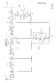
- a typical superheterodyne receiver comprises an input RF section which may contain one or more wide band amplifiers (A1 and A2), suitably coupled, respectively to the antenna 1 and among themselves by means of appropriate LC resonant coupling networks 2, 3, 4, 5 and 6.
- A1 and A2 wide band amplifiers
- the RF section besides amplifying the signals received by the antenna 1, has the function of a pre-selector stage, i.e. capable of eliminating the image frequency f*1, which differs from the tuning frequency f1 by 2f i (i.e. twice the intermediate frequency).
- the frequency conversion stage is formed by a tunable local oscillator 7 (or frequency synthesizer) and by a mixer stage 8.
- the IF stage provides further amplification of the IF signal and determines the selectivity of the receiver by means of one or more band filters 9 and 10, tuned to the selected intermediate frequency (f i ) whose value, conventionally, is comprised between 300 and 600 kHz; the most used values being comprised between 450 and 500 kHz.
- the modulated IF signal, filtered and amplified, is fed to the audio section of the receiver which comprises a detection stage, a pre-amplifier stage and a final power amplifier stage.
- the narrow band AGC system of the receiver utilizes the modulated IF signal (after having been filtered by the band filters 9 and 10). After an optional isolation stage by means of a suitable amplifier A5, the IF signal is detected by a detector 11 and preferably amplified by means of an amplifier A5 to prevent loading the detector.
- the dc component of the detected signal is applied to the bias networks of the preceding amplifying stages (A3, A2 and A1) in order to control the dynamic characteristics thereof, thus avoiding that the stages be driven into saturation by excessively strong signals.
- the narrow band AGC system exerts its control upon the dynamic of the various stages of the receiver exclusively for signals comprised within the tuning band (in other words the signals out-of-tune do not contribute in any way to generating a dc control signal of the AGC system).
- Fig. 3 depicts a block diagram of the same receiver shown in Fig. 2 to which the mixer dynamic control (MDC) system of the invention is applied.
- MDC mixer dynamic control
- the system of the invention contemplates the detection, after an eventual isolation stage A6, of the frequency converted modulated signals before they are filtered by the band filters 9 and 10 of the IF section of the receiver. From the signal detected by means of a suitable detector 13 and preferably amplified by an isolation amplifier A6′, a dc component is extracted by means of a diode 14 and such a dc component is summed to the dc control signal produced by the existing narrow band AGC system.
- the control signal produced by the narrow band AGC system has a much higher level than the control signal produced by the MDC system and therefore it may be said that, when the receiver is tuned, it is the narrow band AGC system exerting predominantly the dynamic control of the preceding stages, conversely, when the receiver is out-of-tune, and therefore the AGC system ceases to exert its function of automatic control of the gain because the control signal produced by the AGC system becomes substantially null, the MDC system continues to produce a control signal of a level sufficient to maintain a correct dynamic within the RF stages for out-of-tune signals, thus preventing the mixer stage 8 from being driven to a saturation condition.
- Fig. 4 shows an embodiment of an MDC circuit of the present invention which may be easily integrated.
- the circuit shown in Fig. 4 is relative to an integrated embodiment of an AM receiver utilizing a differential handling of signals.
- the signal (in differential form) coming from the mixer stage and destined to the IF stage is detected by the pair of transistors Q1 and Q2 and by the capacitor C, and the detected signal is coupled by means of a follower stage Q3 to prevent not loading the detector, to an amplifier stage Q4 which amplifies the detected signal and feed it to a node of application of a control signal of a conventional narrow band AGC system.
Landscapes
- Circuits Of Receivers In General (AREA)
- Control Of Amplification And Gain Control (AREA)
- Input Circuits Of Receivers And Coupling Of Receivers And Audio Equipment (AREA)
- Noise Elimination (AREA)
- Superheterodyne Receivers (AREA)
Applications Claiming Priority (2)
| Application Number | Priority Date | Filing Date | Title |
|---|---|---|---|
| IT8361787 | 1987-04-13 | ||
| IT8783617A IT1214239B (it) | 1987-04-13 | 1987-04-13 | Controllo dinamico di uno stadio mescolatore |
Publications (2)
| Publication Number | Publication Date |
|---|---|
| EP0287524A2 true EP0287524A2 (de) | 1988-10-19 |
| EP0287524A3 EP0287524A3 (de) | 1990-12-27 |
Family
ID=11323203
Family Applications (1)
| Application Number | Title | Priority Date | Filing Date |
|---|---|---|---|
| EP19880830136 Withdrawn EP0287524A3 (de) | 1987-04-13 | 1988-03-30 | Dynamische Steuerung einer Mischstufe |
Country Status (4)
| Country | Link |
|---|---|
| US (1) | US4872206A (de) |
| EP (1) | EP0287524A3 (de) |
| JP (1) | JPS63278407A (de) |
| IT (1) | IT1214239B (de) |
Cited By (2)
| Publication number | Priority date | Publication date | Assignee | Title |
|---|---|---|---|---|
| EP0428173A3 (en) * | 1989-11-15 | 1992-04-22 | Sanyo Electric Co., Ltd. | Radio frequency signal amplifying circuit in radio receiver |
| EP0600637A1 (de) * | 1992-12-01 | 1994-06-08 | Hughes Aircraft Company | Verteiltes System zur Verstärkungsregelung in einem digitalen Empfänger |
Families Citing this family (12)
| Publication number | Priority date | Publication date | Assignee | Title |
|---|---|---|---|---|
| EP0472621A4 (en) * | 1989-05-18 | 1992-08-05 | Motorola, Inc. | Method and apparatus for reducing intermodulation distortion |
| JPH0338906A (ja) * | 1989-07-05 | 1991-02-20 | Pioneer Electron Corp | 受信装置 |
| US5303394A (en) * | 1991-08-09 | 1994-04-12 | Rockwell International | Feedback stabilized Q multiplier filter circuit |
| US5765100A (en) * | 1995-02-03 | 1998-06-09 | Symbol Technologies, Inc. | Communication diversity by image reception |
| GB9508592D0 (en) * | 1995-04-27 | 1995-06-14 | Rca Thomson Licensing Corp | Rf filter and agc circuit |
| US5940143A (en) * | 1995-10-06 | 1999-08-17 | Hitachi, Ltd. | High-definition television signal receiving apparatus and gain control circuit thereof |
| JP3528727B2 (ja) * | 1999-12-08 | 2004-05-24 | 日本電気株式会社 | 受信電力計算回路及びそれを用いた受信機 |
| JP2002118483A (ja) | 2000-10-11 | 2002-04-19 | Matsushita Electric Ind Co Ltd | 無線回路装置及び無線回路装置の制御方法 |
| JP2003218711A (ja) * | 2002-01-22 | 2003-07-31 | Alps Electric Co Ltd | Fm受信機のagc回路 |
| US7212798B1 (en) | 2003-07-17 | 2007-05-01 | Cisco Technology, Inc. | Adaptive AGC in a wireless network receiver |
| KR100788637B1 (ko) * | 2006-10-02 | 2007-12-26 | (주)에프씨아이 | 이득제어 및 다중대역의 처리가 가능한 수신기 |
| US10027355B2 (en) * | 2016-01-19 | 2018-07-17 | Analog Devices Global | Blocker detection based automatic gain control |
Family Cites Families (10)
| Publication number | Priority date | Publication date | Assignee | Title |
|---|---|---|---|---|
| US3495244A (en) * | 1968-10-07 | 1970-02-10 | Hazeltine Research Inc | Interference discriminating apparatus |
| US3665317A (en) * | 1970-04-07 | 1972-05-23 | Rca Corp | Sequential agc system for signal receiver |
| JPS5722245B2 (de) * | 1974-12-28 | 1982-05-12 | ||
| JPS52140820A (en) * | 1976-05-19 | 1977-11-24 | Hitachi Ltd | Shunt motor control system |
| JPS55116681A (en) * | 1979-02-28 | 1980-09-08 | Ngk Insulators Ltd | Ceramic part bonding method |
| JPS5837242B2 (ja) * | 1980-05-19 | 1983-08-15 | 工業技術院長 | 重質油のガス化方法 |
| US4455681A (en) * | 1981-12-21 | 1984-06-19 | Wile Donald T | Dual threshold wide band/narrow band AGC |
| DE3210454A1 (de) * | 1982-03-22 | 1983-09-22 | Licentia Patent-Verwaltungs-Gmbh, 6000 Frankfurt | Empfaenger-eingangsschaltung |
| US4538300A (en) * | 1983-09-07 | 1985-08-27 | Sprague Electric Company | Linear signal strength detector in AM radio |
| JPS6150354U (de) * | 1984-09-03 | 1986-04-04 |
-
1987
- 1987-04-13 IT IT8783617A patent/IT1214239B/it active
-
1988
- 1988-03-30 EP EP19880830136 patent/EP0287524A3/de not_active Withdrawn
- 1988-03-31 US US07/175,994 patent/US4872206A/en not_active Expired - Lifetime
- 1988-04-13 JP JP63091214A patent/JPS63278407A/ja active Pending
Cited By (2)
| Publication number | Priority date | Publication date | Assignee | Title |
|---|---|---|---|---|
| EP0428173A3 (en) * | 1989-11-15 | 1992-04-22 | Sanyo Electric Co., Ltd. | Radio frequency signal amplifying circuit in radio receiver |
| EP0600637A1 (de) * | 1992-12-01 | 1994-06-08 | Hughes Aircraft Company | Verteiltes System zur Verstärkungsregelung in einem digitalen Empfänger |
Also Published As
| Publication number | Publication date |
|---|---|
| IT1214239B (it) | 1990-01-10 |
| IT8783617A0 (it) | 1987-04-13 |
| JPS63278407A (ja) | 1988-11-16 |
| US4872206A (en) | 1989-10-03 |
| EP0287524A3 (de) | 1990-12-27 |
Similar Documents
| Publication | Publication Date | Title |
|---|---|---|
| US4872206A (en) | Mixer dynamic control | |
| EP0829133B1 (de) | Schaltung zur automatischen verstärkungsregelung in einem tuner | |
| EP0512374B1 (de) | Tonpegelentzerrung von Fernseh-, FM-Rundfunk- und FM-Wetterdiensttonsignalen | |
| US4249261A (en) | Superheterodyne radio receiver with nearby-station interference detection | |
| US4974087A (en) | Parallel sound if with reference carrier derived from quasi-synchronous video detector | |
| JPH07176969A (ja) | 歪対策受信回路 | |
| US3919645A (en) | AM/FM radio receiver | |
| CA1072638A (en) | Transceiver audio system | |
| US3626294A (en) | Carrier-plus-noise to noise-operated am squelch circuit | |
| US3495031A (en) | Variable q i.f. amplifier circuit for a television receiver | |
| KR100211620B1 (ko) | 텔레비젼 수상기의 fm 라디오에 사용된 고정된 제2하프-if 트랩을 갖는 제1 if 필터 | |
| US4455674A (en) | Amplitude-modulated signal receiver having a variable Q circuit | |
| US2404338A (en) | Noise suppression circuits | |
| US5523801A (en) | Upper and lower adjacent picture signal traps | |
| US3842198A (en) | Sound demodulator and afc system | |
| JPH10190509A (ja) | マイクロ波放送受信回路 | |
| EP1383318A2 (de) | Beseitigung des Einflusses von analogen Signalen während des Empfangs von digitalen Signalen in einem Fernsehtuner | |
| CA1057847A (en) | Frequency selective circuit for automatic frequency control and sound signals | |
| US2036022A (en) | Method of and means for receiving signals | |
| EP0291935A2 (de) | FMX-Stereoempfänger | |
| JPH0134407B2 (de) | ||
| JPS60212038A (ja) | 受信機 | |
| US3080529A (en) | Plural input signal translating system | |
| US2165252A (en) | Phase modulation receiver | |
| US2611860A (en) | Single side band radio signaling |
Legal Events
| Date | Code | Title | Description |
|---|---|---|---|
| PUAI | Public reference made under article 153(3) epc to a published international application that has entered the european phase |
Free format text: ORIGINAL CODE: 0009012 |
|
| AK | Designated contracting states |
Kind code of ref document: A2 Designated state(s): DE FR GB NL SE |
|
| RAP1 | Party data changed (applicant data changed or rights of an application transferred) |
Owner name: SGS-THOMSON MICROELECTRONICS S.R.L. |
|
| PUAL | Search report despatched |
Free format text: ORIGINAL CODE: 0009013 |
|
| AK | Designated contracting states |
Kind code of ref document: A3 Designated state(s): DE FR GB NL SE |
|
| 17P | Request for examination filed |
Effective date: 19910605 |
|
| D17P | Request for examination filed (deleted) | ||
| R17P | Request for examination filed (corrected) |
Effective date: 19910521 |
|
| 17Q | First examination report despatched |
Effective date: 19920626 |
|
| STAA | Information on the status of an ep patent application or granted ep patent |
Free format text: STATUS: THE APPLICATION HAS BEEN WITHDRAWN |
|
| 18W | Application withdrawn |
Withdrawal date: 19971022 |