EP0287552B1 - Dispositif de pulvérisation d'un fluide - Google Patents
Dispositif de pulvérisation d'un fluide Download PDFInfo
- Publication number
- EP0287552B1 EP0287552B1 EP19880890086 EP88890086A EP0287552B1 EP 0287552 B1 EP0287552 B1 EP 0287552B1 EP 19880890086 EP19880890086 EP 19880890086 EP 88890086 A EP88890086 A EP 88890086A EP 0287552 B1 EP0287552 B1 EP 0287552B1
- Authority
- EP
- European Patent Office
- Prior art keywords
- electrodes
- electrode
- nozzle
- spraying
- insulators
- Prior art date
- Legal status (The legal status is an assumption and is not a legal conclusion. Google has not performed a legal analysis and makes no representation as to the accuracy of the status listed.)
- Expired - Lifetime
Links
- 238000005507 spraying Methods 0.000 title claims description 33
- 239000012530 fluid Substances 0.000 title 1
- 239000007921 spray Substances 0.000 claims description 29
- 239000012212 insulator Substances 0.000 claims description 23
- 239000003795 chemical substances by application Substances 0.000 claims description 16
- 238000007786 electrostatic charging Methods 0.000 claims description 6
- 238000007600 charging Methods 0.000 description 4
- 238000009413 insulation Methods 0.000 description 4
- 239000007788 liquid Substances 0.000 description 4
- 239000003595 mist Substances 0.000 description 4
- 239000002245 particle Substances 0.000 description 4
- 238000000926 separation method Methods 0.000 description 4
- 230000005684 electric field Effects 0.000 description 3
- XLYOFNOQVPJJNP-UHFFFAOYSA-N water Substances O XLYOFNOQVPJJNP-UHFFFAOYSA-N 0.000 description 3
- 238000005253 cladding Methods 0.000 description 2
- 238000010586 diagram Methods 0.000 description 2
- 239000000725 suspension Substances 0.000 description 2
- 230000006978 adaptation Effects 0.000 description 1
- 238000010276 construction Methods 0.000 description 1
- 230000005484 gravity Effects 0.000 description 1
- 238000001556 precipitation Methods 0.000 description 1
- 230000000717 retained effect Effects 0.000 description 1
- 230000003068 static effect Effects 0.000 description 1
Images


Classifications
-
- B—PERFORMING OPERATIONS; TRANSPORTING
- B05—SPRAYING OR ATOMISING IN GENERAL; APPLYING FLUENT MATERIALS TO SURFACES, IN GENERAL
- B05B—SPRAYING APPARATUS; ATOMISING APPARATUS; NOZZLES
- B05B5/00—Electrostatic spraying apparatus; Spraying apparatus with means for charging the spray electrically; Apparatus for spraying liquids or other fluent materials by other electric means
- B05B5/08—Plant for applying liquids or other fluent materials to objects
- B05B5/085—Plant for applying liquids or other fluent materials to objects the plant being provided on a vehicle
Definitions
- the invention relates to a device for spraying spraying agent with a spraying device supported on or pulled by a towing vehicle, the spraying device having at least one spray nozzle which is fed with spraying agent via a pump, in which the distance from the nozzle orifice (s) en) electrodes are arranged for the electrostatic charging of the spray.
- Spraying devices for agricultural purposes can be pulled by a towing vehicle or, for example, can be attached to the three-point suspension of an agricultural towing vehicle, such as a tractor.
- the spraying agent is brought out of a spraying agent container by means of a pump via spraying nozzles, whereby the spraying nozzles can be oriented transversely to the direction of travel, for example, and blowers can be provided with individual of these spraying devices, which generate a carrier air flow for the spraying agent released by the nozzles.
- a device of this type can be found, for example, in European patent application 167 518. Spraying devices of this type produce a spray mist, depending on the type and cultivation of the plants to be sprayed, a more or less large proportion of the spray liquid becomes ineffective for spraying purposes or is lost as a drift for use.
- the device according to the invention is essentially characterized in that the electrodes are fixed to an insulated electrode carrier separate from the nozzle carrier, the electrode carrier being supported in an insulating manner on the housing and / or on the container.
- the fact that separate insulated electrode supports are provided for the electrodes and thus the electrodes are not connected directly to the nozzles or nozzle supports ensures that no significant leakage currents flow between the nozzle mouth and the electrodes even in the oversaturated mist phase.
- the design of the insulation is of particular importance in order to achieve a functional device in which the desired electrostatic charging is possible.
- the arrangement of the electrodes on the electrode holder, which is separate from the nozzle holder and insulated from it, means that there is no need for complex suction devices on the electrodes, as a result of which they can be constructed much more simply.
- the insulation and support of the electrode carrier on the housing and / or container of the spraying device can be carried out using simple means.
- spray agent Since the spray agent is electrostatically charged when or after it emerges from the spray nozzles, it is attracted to the target areas at ground potential and a large part of the drifting spray agent can be directed directly at the plants or the target areas.
- spraying agent also reaches the leaves from the underside or the shadow of the spray shadow, so that a much larger proportion of the sprayed liquid is accepted by the plants not only on the top but also on the underside, which means particularly effective protection or effective treatment is made possible and, above all, untreated nests are avoided.
- the spray can be negatively charged, which can be done by corona, contact or influential charging.
- the device according to the invention is further developed such that a positive voltage of 10 to 15 kV, in particular 12 kV, is (are) applied to the electrode (s), the electrodes being advantageously displaceable relative to the nozzles for better adjustment of the electrodes are arranged on the electrode carrier.
- brushes or comb-shaped electrodes can be used as electrodes, the electrodes preferably being of annular design.
- Such annular electrodes can be arranged in a particularly simple manner in accordance with the nozzle mouth, in particular coaxially to the nozzle mouths, so that an effective electrostatic charging of the jet leaving the spray nozzles is ensured.
- each annular electrode is advantageously formed with an inner surface which is conical in accordance with the spray cone of the spray nozzle.
- the design is advantageously made such that the insulators, via which the electrode carrier is connected or supported on the housing and / or container and / or the electrodes on the electrode carrier, with pots with a downward opening are disguised.
- the cup-shaped cladding drains the precipitated water without it coming into direct contact with the surface of the insulators.
- the arrangement of these pot-shaped linings thus protects the insulator against the separation of spray droplets, these linings formed by pots preferably being able to be connected to earth potential, as a result of which the insulator can be further secured against the precipitation of droplets of moisture.
- the electrode carrier is arranged below the insulators and / or suspended from them.
- An electric field is formed between the linings of the insulators and the insulators and the electrode carrier, which are preferably at ground potential, as a result of which a force is exerted on charged particles which are located on the electrode carrier in the direction of the pot-shaped lining or the insulator.
- the electrode carrier is arranged below the insulators and / or hanging from them, gravity acts on the particles located on the electrode carrier against the direction of the electric field, as a result of which the transfer of a charged particle from the electrode carrier to the cup-shaped cladding and thus a corresponding outflow the load is largely avoided. It is thus ensured that no leakage current can flow from the electrode carrier via the insulators.
- the electrode carrier is advantageously connected to the housing and / or the container via the insulators with the interposition of an insulating carrier frame.
- a carrier frame makes it possible, on the one hand, to ensure the static stability of the electrode carrier, and, on the other hand, to bring the insulators out of the mist area of the spray nozzles and the electrode carrier.
- an insulating support frame makes it possible to gradually reduce the voltage prevailing between the electrode support and the insulator linings, which are preferably at ground potential, so that the support frame has a potential which lies between the potential of the electrode support and ground potential.
- FIG. 1 shows a circuit diagram for the electrostatic charging of the spraying agent when or after it emerges from the spray nozzles
- FIG. 2 shows, in an enlarged view, a diagram for the charge separation during influential charging
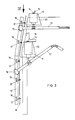
- FIG. 3 shows a partial view of an electrode carrier supported on a housing
- Figure 4 is a view in the direction of arrow IV of Figure 3.
- a nozzle designated 1 is acted upon by a pump 3 with spray medium from a storage container 4 via a pressure regulator 2.
- An electrode 5 is arranged concentrically with the nozzle 1 and is supplied with a voltage of, for example, 12 kV via a high-voltage device 6, which is fed, for example, from a battery 7 of the towing vehicle.
- the towing vehicle and the sprayer with the nozzle 1 are at ground potential, as is indicated by an earth band 8 on the sprayer.
- the spray medium emerging from the nozzle 1 is electrostatically charged when or after exiting when it passes through the electrode 5.
- an electrode carrier 10 is connected via insulators 11 with the interposition of an insulating support frame 12 to a housing of a spraying device, not shown.
- the insulators have pot-shaped linings 13 with an opening directed downwards.
- the insulators 11 and the cup-shaped linings 13 are supported at 14 on a frame element 15 which is connected to the housing of the spraying device.
- the electrode carrier 10 has an electrode at each of the locations designated by 16, which cooperate with nozzles 17 of a schematically indicated spray medium supply line 18, which is supported independently of the carrier frame 12 and the electrode carrier 10 on the housing of the spraying device or on the container.
- FIG. 3 A detail of FIG. 3 is shown enlarged in FIG. 4, the reference symbols being retained.
- the support frame 12 is angled at the connection 19 with the electrode support 10, which makes it possible to bring the insulator out of the fog area of the spray.
- the spraying agent is supplied via the line indicated by 18 to a nozzle 17, an annular electrode 16 being provided coaxially with the nozzle 17.
- the electrode 16 has an inner surface which is conical in accordance with the spray cone of the spray nozzle 17.
- the pot-shaped coverings In the area of the support frame 12, the pot-shaped coverings have baffles 20 on their lower edge, which prevent liquid collected on the surface of the cover from dripping onto the support frame 12 underneath.
- the electrodes 16 can be slidably fixed on the electrode carrier 10 in the sense of the double arrow 21, as a result of which a better adaptation and adjustment of the electrodes can be achieved.
Landscapes
- Electrostatic Spraying Apparatus (AREA)
- Application Of Or Painting With Fluid Materials (AREA)
Claims (11)
- Dispositif pour pulvériser un agent de traitement comportant un équipement de pulvérisation monté sur un véhicule tracteur ou tracté par ce dernier, l'équipement de pulvérisation comportant au moins une buse de pulvérisation (17) alimentée en agent de traitement par une pompe (3), des électrodes (16) pour la charge électrostatique de l'agent de traitement étant disposées à distance de la ou des orifices de buses, caractérisé par le fait que les électrodes (16) sont fixées sur un porte-électrodes (10) isolé, séparé du porte-buses (18), le porte-électrodes (10) étant monté sur le carter et/ou le réservoir.
- Dispositif selon la revendication 1, caractérisé par le fait que la ou les électrodes (16) sont soumises à une tension positive de 10 à 15 kV, en particulier 12 kV.
- Dispositif selon la revendication 1 ou 2, caractérisé par le fait que les électrodes (16) sont montées déplaçables sur le porte-électrodes (10).
- Dispositif selon l'une des revendications 1, 2 ou 3, caractérisé par le fait que les électrodes (16) sont sous la forme d'aiguilles, de balais ou de peignes.
- Dispositif selon l'une des revendications 1, 2 ou 3, caractérisé par le fait que les électrodes (16) sont de forme annulaire.
- Dispositif selon la revendication 5, caractérisé par le fait que les électrodes annulaires (16) sont disposées en correspondance avec les orifices de buses (17), en particulier sont disposées coaxialement à celles-ci.
- Dispositif selon la revendication 5 ou 6, caractérisé par le fait que chaque électrode annulaire (16) comporte une surface intérieure conique correspondant au cône de projection de la buse de pulvérisation (17)
- Dispositif selon l'une des revendications 1 à 7, caractérisé par le fait que les isolateurs (11) par lesquels le porte-électrodes (10) est raccordé au carter et/ou au réservoir et/ou par lesquels les électrodes (16) sont supportées sur le porte-électrodes (10) sont revêtus de pots (13) comportant une ouverture dirigée vers le bas.
- Dispositif selon la revendication 8, caractérisé par le fait que les revêtements pour les isolateurs, formés par les pots (13), sont mis au potentiel de la terre.
- Dispositif selon la revendication 8 ou 9, caractérisé par le fait que le porte-électrodes (10) est disposé en-dessous des isolateurs (11) et/ou suspendu à ceux-ci.
- Dispositif selon l'une des revendications 1 à 10, caractérisé par le fait que le porte-électrodes (10) est raccordé au carter et/ou au réservoir par l'intermédiaire des isolateurs (11) avec interposition d'un cadre-support isolant (12).
Applications Claiming Priority (2)
| Application Number | Priority Date | Filing Date | Title |
|---|---|---|---|
| AT886/87 | 1987-04-09 | ||
| AT88687A AT395505B (de) | 1987-04-09 | 1987-04-09 | Vorrichtung zum verspruehen von spritzmitteln |
Publications (3)
| Publication Number | Publication Date |
|---|---|
| EP0287552A2 EP0287552A2 (fr) | 1988-10-19 |
| EP0287552A3 EP0287552A3 (en) | 1990-03-07 |
| EP0287552B1 true EP0287552B1 (fr) | 1992-10-21 |
Family
ID=3502085
Family Applications (1)
| Application Number | Title | Priority Date | Filing Date |
|---|---|---|---|
| EP19880890086 Expired - Lifetime EP0287552B1 (fr) | 1987-04-09 | 1988-04-07 | Dispositif de pulvérisation d'un fluide |
Country Status (3)
| Country | Link |
|---|---|
| EP (1) | EP0287552B1 (fr) |
| AT (1) | AT395505B (fr) |
| DE (1) | DE3875366D1 (fr) |
Cited By (2)
| Publication number | Priority date | Publication date | Assignee | Title |
|---|---|---|---|---|
| CN103551288A (zh) * | 2013-10-22 | 2014-02-05 | 杭州冯氏彩钢板有限公司 | 横向高压静电棒彩钢板涂塑装备 |
| WO2016167410A1 (fr) * | 2015-04-14 | 2016-10-20 | 김장환 | Appareil de pulvérisation électrostatique de longue distance |
Families Citing this family (5)
| Publication number | Priority date | Publication date | Assignee | Title |
|---|---|---|---|---|
| GB2260366A (en) * | 1991-10-09 | 1993-04-14 | Susan Margaret Mills | I.c. engine piston valve gear |
| IT1392622B1 (it) * | 2008-10-23 | 2012-03-16 | Nobili S P A | Apparecchiatura di irrorazione, procedimento e dispositivo di verifica. |
| DE102017001827A1 (de) | 2016-09-16 | 2018-03-22 | Zasso Gmbh | Vorrichtung zur Zerstörung von Pflanzen |
| GR1009689B (el) * | 2018-05-14 | 2020-01-24 | Τρυφων Γεωργιος Φαρμουζης | Συστημα ανορθωτη και φορτιζομενης με συνεχες ρευμα ανοξειδωτης στεφανης με οδοντωτη μορφη τοποθετημενης με μονωτηρες στην πλατη νεφελοψεκαστηρα για εφαρμογη ηλεκτροστατικου ψεκασμου |
| US20240424506A1 (en) * | 2023-06-22 | 2024-12-26 | Raven Industries, Inc. | Electrostatic spraying system and methods for same |
Family Cites Families (6)
| Publication number | Priority date | Publication date | Assignee | Title |
|---|---|---|---|---|
| DD126675A5 (fr) * | 1975-06-19 | 1977-08-03 | ||
| HU175744B (hu) * | 1976-11-09 | 1980-10-28 | Hajtomuevek Es Festoberendeze | Ustrojstvo dlja ehlektrostaticheskogo kraskoraspylenija s uluchshennym koehfficientom poleznogo dejstvija pri raspylenii krasok, razbavljaemykh vodoj |
| CH622444A5 (fr) * | 1977-04-04 | 1981-04-15 | Gruenenfelder H Eltex Elektron | |
| US4489894A (en) * | 1981-02-27 | 1984-12-25 | National Research Development Corporation | Inductively charged spraying apparatus |
| AT385393B (de) * | 1984-07-04 | 1988-03-25 | Krobath Maschf Ferd | Spritzgeraet, insbesondere fuer landwirtschaftliche zwecke |
| DE3429075A1 (de) * | 1984-08-07 | 1986-02-20 | Hermann Behr & Sohn Gmbh & Co, 7121 Ingersheim | Vorrichtung zum elektrostatischen beschichten von gegenstaenden |
-
1987
- 1987-04-09 AT AT88687A patent/AT395505B/de not_active IP Right Cessation
-
1988
- 1988-04-07 DE DE8888890086T patent/DE3875366D1/de not_active Expired - Fee Related
- 1988-04-07 EP EP19880890086 patent/EP0287552B1/fr not_active Expired - Lifetime
Cited By (2)
| Publication number | Priority date | Publication date | Assignee | Title |
|---|---|---|---|---|
| CN103551288A (zh) * | 2013-10-22 | 2014-02-05 | 杭州冯氏彩钢板有限公司 | 横向高压静电棒彩钢板涂塑装备 |
| WO2016167410A1 (fr) * | 2015-04-14 | 2016-10-20 | 김장환 | Appareil de pulvérisation électrostatique de longue distance |
Also Published As
| Publication number | Publication date |
|---|---|
| DE3875366D1 (de) | 1992-11-26 |
| EP0287552A3 (en) | 1990-03-07 |
| AT395505B (de) | 1993-01-25 |
| EP0287552A2 (fr) | 1988-10-19 |
| ATA88687A (de) | 1992-06-15 |
Similar Documents
| Publication | Publication Date | Title |
|---|---|---|
| DE2937879C2 (fr) | ||
| DE2731712C2 (de) | Tragbares Zerstäubungsgerät | |
| DE2630555A1 (de) | Vorrichtung und verfahren zum elektrostatischen spruehen | |
| CH639874A5 (en) | Method and appliance for electrostatic atomisation of liquids | |
| DD255482A5 (de) | Vorrichtung zum elektrostatischen beschichten von gegenstaenden | |
| DE1825025U (de) | Handspritspistole. | |
| DE3319995A1 (de) | Elektrostatisches spritzgeraet | |
| DE4105116A1 (de) | Vorrichtung und verfahren zum elektrostatischen beschichten von gegenstaenden | |
| DE3203729C2 (fr) | ||
| AT395505B (de) | Vorrichtung zum verspruehen von spritzmitteln | |
| EP0134951B1 (fr) | Procédé et dispositif pour dispenser et répandre sur grandes surfaces des liquides électriquement conducteurs | |
| DE3707547A1 (de) | Verfahren und vorrichtung zum verspritzen von pflanzenschutzmittelloesungen oder -dispersionen | |
| DE1466075B2 (de) | Anordnung zur vermeidung statischer aufladungen bei flugzeugen | |
| DE2159909A1 (de) | Verfahren und Luftfahrzeug zum Versprühen von landwirtschaftlichen Nutzstoffen | |
| DE3207002A1 (de) | Spritzvorrichtung | |
| EP0171042A1 (fr) | Dispositif pour l'enduction électrostatique d'articles | |
| AT234878B (de) | Verfahren zum elektrostatischen Zerstäuben von Flüssigkeiten | |
| DE3317650A1 (de) | Elektrostatisches verspritzen bzw. verspruehen von elektrisch leitfaehigen fluessigkeiten, z. b. pflanzenbehandlungsmitteln | |
| DE1156341B (de) | Elektrostatische Auftragsvorrichtung | |
| DD229046A1 (de) | Verfahren und vorrichtung zur applikation von pflanzenschutzmitteln | |
| DE413165C (de) | Verfahren zum Veraendern der atmosphaerischen Zustaende | |
| DE3644849A1 (de) | Elektrostatische sprueheinrichtung fuer beschichtungspulver | |
| DE975017C (de) | Spuelvorrichtung fuer das periodische Abwaschen der Elektroden von Nasselektrofiltern | |
| DE2546025B2 (de) | Vorrichtung zum elektrostatischen Besprühen von fortlaufend transportierten Bahnen | |
| AT238348B (de) | Farbspritzpistole für elektrostatisches Farbenspritzen |
Legal Events
| Date | Code | Title | Description |
|---|---|---|---|
| PUAI | Public reference made under article 153(3) epc to a published international application that has entered the european phase |
Free format text: ORIGINAL CODE: 0009012 |
|
| AK | Designated contracting states |
Kind code of ref document: A2 Designated state(s): CH DE FR GB IT LI NL |
|
| ITCL | It: translation for ep claims filed |
Representative=s name: SAIC BREVETTI S.R.L. |
|
| PUAL | Search report despatched |
Free format text: ORIGINAL CODE: 0009013 |
|
| AK | Designated contracting states |
Kind code of ref document: A3 Designated state(s): CH DE FR GB IT LI NL |
|
| 17P | Request for examination filed |
Effective date: 19900814 |
|
| 17Q | First examination report despatched |
Effective date: 19910903 |
|
| RAP1 | Party data changed (applicant data changed or rights of an application transferred) |
Owner name: ASCHER GESELLSCHAFT M.B.H. |
|
| GRAA | (expected) grant |
Free format text: ORIGINAL CODE: 0009210 |
|
| AK | Designated contracting states |
Kind code of ref document: B1 Designated state(s): CH DE FR GB IT LI NL |
|
| REF | Corresponds to: |
Ref document number: 3875366 Country of ref document: DE Date of ref document: 19921126 |
|
| ITF | It: translation for a ep patent filed | ||
| ET | Fr: translation filed | ||
| GBT | Gb: translation of ep patent filed (gb section 77(6)(a)/1977) |
Effective date: 19930115 |
|
| REG | Reference to a national code |
Ref country code: CH Ref legal event code: PUE Owner name: FERDINAND KROBATH MASCHINENFABRIK |
|
| REG | Reference to a national code |
Ref country code: GB Ref legal event code: 732E |
|
| PGFP | Annual fee paid to national office [announced via postgrant information from national office to epo] |
Ref country code: GB Payment date: 19930325 Year of fee payment: 6 |
|
| PGFP | Annual fee paid to national office [announced via postgrant information from national office to epo] |
Ref country code: FR Payment date: 19930330 Year of fee payment: 6 |
|
| ITPR | It: changes in ownership of a european patent |
Owner name: CESSIONE;FERDINAND KROBATH MASCHINENFABRIK |
|
| PGFP | Annual fee paid to national office [announced via postgrant information from national office to epo] |
Ref country code: NL Payment date: 19930430 Year of fee payment: 6 |
|
| PGFP | Annual fee paid to national office [announced via postgrant information from national office to epo] |
Ref country code: CH Payment date: 19930625 Year of fee payment: 6 |
|
| REG | Reference to a national code |
Ref country code: FR Ref legal event code: TP |
|
| PLBE | No opposition filed within time limit |
Free format text: ORIGINAL CODE: 0009261 |
|
| STAA | Information on the status of an ep patent application or granted ep patent |
Free format text: STATUS: NO OPPOSITION FILED WITHIN TIME LIMIT |
|
| 26N | No opposition filed | ||
| NLS | Nl: assignments of ep-patents |
Owner name: FERDINAND KROBATH MASCHINENFABRIK TE FELDBACH, OOS |
|
| PG25 | Lapsed in a contracting state [announced via postgrant information from national office to epo] |
Ref country code: GB Effective date: 19940407 |
|
| PG25 | Lapsed in a contracting state [announced via postgrant information from national office to epo] |
Ref country code: LI Effective date: 19940430 Ref country code: CH Effective date: 19940430 |
|
| PG25 | Lapsed in a contracting state [announced via postgrant information from national office to epo] |
Ref country code: NL Effective date: 19941101 |
|
| GBPC | Gb: european patent ceased through non-payment of renewal fee |
Effective date: 19940407 |
|
| NLV4 | Nl: lapsed or anulled due to non-payment of the annual fee | ||
| PG25 | Lapsed in a contracting state [announced via postgrant information from national office to epo] |
Ref country code: FR Effective date: 19941229 |
|
| REG | Reference to a national code |
Ref country code: CH Ref legal event code: PL |
|
| REG | Reference to a national code |
Ref country code: FR Ref legal event code: ST |
|
| PGFP | Annual fee paid to national office [announced via postgrant information from national office to epo] |
Ref country code: DE Payment date: 20000621 Year of fee payment: 13 |
|
| PG25 | Lapsed in a contracting state [announced via postgrant information from national office to epo] |
Ref country code: DE Free format text: LAPSE BECAUSE OF NON-PAYMENT OF DUE FEES Effective date: 20020201 |
|
| PG25 | Lapsed in a contracting state [announced via postgrant information from national office to epo] |
Ref country code: IT Free format text: LAPSE BECAUSE OF NON-PAYMENT OF DUE FEES;WARNING: LAPSES OF ITALIAN PATENTS WITH EFFECTIVE DATE BEFORE 2007 MAY HAVE OCCURRED AT ANY TIME BEFORE 2007. THE CORRECT EFFECTIVE DATE MAY BE DIFFERENT FROM THE ONE RECORDED. Effective date: 20050407 |