EP0287672A1 - Systeme d'affectation de couleurs - Google Patents
Systeme d'affectation de couleurs Download PDFInfo
- Publication number
- EP0287672A1 EP0287672A1 EP87906473A EP87906473A EP0287672A1 EP 0287672 A1 EP0287672 A1 EP 0287672A1 EP 87906473 A EP87906473 A EP 87906473A EP 87906473 A EP87906473 A EP 87906473A EP 0287672 A1 EP0287672 A1 EP 0287672A1
- Authority
- EP
- European Patent Office
- Prior art keywords
- signal
- conversion table
- image
- image data
- latch
- Prior art date
- Legal status (The legal status is an assumption and is not a legal conclusion. Google has not performed a legal analysis and makes no representation as to the accuracy of the status listed.)
- Withdrawn
Links
- 238000013507 mapping Methods 0.000 title claims abstract description 10
- 238000006243 chemical reaction Methods 0.000 claims abstract description 34
- 235000019646 color tone Nutrition 0.000 abstract description 13
- 238000000034 method Methods 0.000 abstract 1
- 238000010586 diagram Methods 0.000 description 3
- 241000282414 Homo sapiens Species 0.000 description 1
- 230000001419 dependent effect Effects 0.000 description 1
Images
Classifications
-
- G—PHYSICS
- G09—EDUCATION; CRYPTOGRAPHY; DISPLAY; ADVERTISING; SEALS
- G09G—ARRANGEMENTS OR CIRCUITS FOR CONTROL OF INDICATING DEVICES USING STATIC MEANS TO PRESENT VARIABLE INFORMATION
- G09G5/00—Control arrangements or circuits for visual indicators common to cathode-ray tube indicators and other visual indicators
- G09G5/02—Control arrangements or circuits for visual indicators common to cathode-ray tube indicators and other visual indicators characterised by the way in which colour is displayed
- G09G5/06—Control arrangements or circuits for visual indicators common to cathode-ray tube indicators and other visual indicators characterised by the way in which colour is displayed using colour palettes, e.g. look-up tables
Definitions
- the present invention relates to a color mapping system for use in industrial color television or the like, and more particularly to a color mapping system which can easily select a conversion table for converting color tones.
- an image taken by a television camera is stored as a digital gray scale (indicating density gradations) image.
- a gray scale output signal from an image processing circuit is converted to a color signal based on a predetermined table.
- a control signal for selecting a color tone is separately produced for selecting a conversion table.
- the conventional system is however disadvantageous in that it requires special controlling hardware and results in complex control.
- a color mapping system for varying the color tone of image data, comprising:
- the selection signal for the conversion table is transferred using the image data bus, and simultaneously a strobe signal is produced from an image processing device and stored in the latch. Therefore, a conversion table can easily be selected.
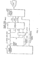
- FIG. 1 is a block diagram of an embodiment of the present invention.
- An image processing circuit 1 produces an image signal, a selection data recognizing signal, and a synchronizing signal.
- the image processing circuit 1 stores a video signal from a television camera as a digital 8-bit gray scale signal.
- An image data bus 2 is of an 8-bit structure including 4 bits used also for transferring a signal for selecting a conversion table.
- a latch 3 stores a selection signal for a conversion table.
- a strobe signal line 4 transfers a strobe signal when a selection signal for a conversion table is transferred over the 4 bits of the image data bus-2.
- a color tone conversion table 5 converts an 8-bit signal from the image data bus 2 according to a corresponding table therein.
- the color tone conversion table 5 has 16 conversion tables stored in a R OM.
- Image output lines 7, 8, 9 transfer a red image (R), a green image (G), and a blue image (B), respectively.
- a display control circuit 10 converts a chrominance signal or the like to a display signal.
- a display unit 11 comprises a color CRT. Denoted at 12 is a synchronizing signal.
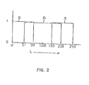
- FIG. 2 shows, by way of example, a conversion table in the color tone conversion table 5.
- the horizontal axis of FIG. 2 represents a gray scale (indicating density gradations) in numerical values ranging from 1 to 256. The greater the numerical values, the lighter the gradations.
- the vertical axis indicates on and off conditions of a corresponding chrominance signal. The signal is on when it is of.”1", and off when it is of "0".
- the gray scale signal when the gray scale signal ranges from 1 to 51, only the blue image (B) is on.
- the gray scale signal ranges from 52 to 91 the blue image (B) and the green image (G) are on, and the display unit 11 displays bluish green color.
- the gray scale signal ranges from 92 to 165, only the blue image ( B ) is on.
- the gray scale signal ranges from 166 to 205, the green image (G) and the red image (R)-are on.
- the gray scale signal ranges from 206 to 256, only the red image (R) is on.
- the color tone converstion table contains the 16 conversion tables for determining which color the gray scale signal is to be converted to. One of the 16 conversion tables is selected by a signal from the latch 3.
- the conversion table selection signal is transferred using the image data bus 2 and stored in the latch 3. Therefore, conversion to the color tone can easily be effected by a simple arrangement.
- the image data bus is of 8 bits
- the conversion table selection signal is of 4 bits.
- they are not limited to these bits, but may be of desired bits dependent on the application.
- the conversion table selection signal is transferred using a portion of the image data bus, and stored in the latch in response to the strobe signal. Accordingly, the color tone can easily be varied without the need for any special control line.
Landscapes
- Engineering & Computer Science (AREA)
- Physics & Mathematics (AREA)
- Computer Hardware Design (AREA)
- General Physics & Mathematics (AREA)
- Theoretical Computer Science (AREA)
- Image Processing (AREA)
- Processing Of Color Television Signals (AREA)
- Processing Or Creating Images (AREA)
- Image Analysis (AREA)
Abstract
Un système d'affectation de couleurs fait correspondre des couleurs aux signaux de l'échelle de gris de télévisions industrielles en couleurs afin de de changer la nuance des données d'image. Le système comprend un tableau de conversion de nuances (5) ayant une pluralité de tables de conversion et une bascule (3) qui enregistre un signal de sélection des tables de conversion. Une ligne de signaux d'échantillonnage (4) permet à une partie d'un bus de données d'image (2) de relier le bus de données d'image (2) à la bascule (3), de façon à informer la bascule (3) sur le fait que le signal de sélection est transféré. Le signal d'échantillonnage détermine le signal de sélection de la table de conversion à la bascule (3). Les couleurs sont affectées aux signaux de l'échelle de gris selon une table de conversion sélectionnée par le signal de sélection des tables enregistré dans la bascule (3).
Applications Claiming Priority (2)
| Application Number | Priority Date | Filing Date | Title |
|---|---|---|---|
| JP243951/86 | 1986-10-14 | ||
| JP61243951A JPS6398073A (ja) | 1986-10-14 | 1986-10-14 | カラ−マツピング方式 |
Publications (2)
| Publication Number | Publication Date |
|---|---|
| EP0287672A1 true EP0287672A1 (fr) | 1988-10-26 |
| EP0287672A4 EP0287672A4 (fr) | 1989-04-12 |
Family
ID=17111462
Family Applications (1)
| Application Number | Title | Priority Date | Filing Date |
|---|---|---|---|
| EP19870906473 Withdrawn EP0287672A4 (fr) | 1986-10-14 | 1987-10-06 | Systeme d'affectation de couleurs. |
Country Status (3)
| Country | Link |
|---|---|
| EP (1) | EP0287672A4 (fr) |
| JP (1) | JPS6398073A (fr) |
| WO (1) | WO1988002906A1 (fr) |
Family Cites Families (3)
| Publication number | Priority date | Publication date | Assignee | Title |
|---|---|---|---|---|
| FR2487616A1 (fr) * | 1980-07-28 | 1982-01-29 | Electronique Inf System | Procede et dispositif pour la synthese de signaux video couleur a partir d'un signal video noir et blanc |
| GB2090506B (en) * | 1980-11-12 | 1984-07-18 | British Broadcasting Corp | Video colour graphics apparatus |
| JPS61107293A (ja) * | 1984-10-30 | 1986-05-26 | 株式会社東芝 | 疑似カラ−モニタ装置 |
-
1986
- 1986-10-14 JP JP61243951A patent/JPS6398073A/ja active Pending
-
1987
- 1987-10-06 EP EP19870906473 patent/EP0287672A4/fr not_active Withdrawn
- 1987-10-06 WO PCT/JP1987/000751 patent/WO1988002906A1/fr not_active Ceased
Also Published As
| Publication number | Publication date |
|---|---|
| EP0287672A4 (fr) | 1989-04-12 |
| JPS6398073A (ja) | 1988-04-28 |
| WO1988002906A1 (fr) | 1988-04-21 |
Similar Documents
| Publication | Publication Date | Title |
|---|---|---|
| US5124688A (en) | Method and apparatus for converting digital YUV video signals to RGB video signals | |
| JPH0426471B2 (fr) | ||
| EP0088583B1 (fr) | Dispositif de traitement d'image | |
| US4559531A (en) | Color video generator | |
| US5943097A (en) | Image processing means for processing image signals of different signal formats | |
| EP0287672A1 (fr) | Systeme d'affectation de couleurs | |
| US4903227A (en) | Processor for digitized video having common bus for real time transfer of input and output video data | |
| US20020051165A1 (en) | Image processing device and image data conversion method | |
| JPH096306A (ja) | 画像フレームメモリ | |
| EP0543511A1 (fr) | Méthode et appareil de conversion de données | |
| JPS61107293A (ja) | 疑似カラ−モニタ装置 | |
| JP2832962B2 (ja) | 中間調表示回路 | |
| JP2567759B2 (ja) | 探知画像カラー表示装置 | |
| EP0148659A2 (fr) | Circuit de commande d'affichage vidéo | |
| JPH08126028A (ja) | データ伝送システム | |
| JPS62165687A (ja) | カ−ソル表示方式 | |
| KR20010004879A (ko) | 액정 표시 장치의 영상 신호 입력 장치 | |
| JP2610272B2 (ja) | マトリクス変換装置 | |
| JP2745510B2 (ja) | 映像信号処理装置 | |
| JPS6346071A (ja) | カラー画像処理装置 | |
| JPH0413894Y2 (fr) | ||
| JPS6020756B2 (ja) | 陰極線管デイスプレイ装置 | |
| JPS6236394Y2 (fr) | ||
| EP0258947A3 (fr) | Circuit d'interface de signaux numériques de couleur pour un moniteur vidéo | |
| JPH01183685A (ja) | ルックアップテーブルメモリを用いたマルチメディア画像表示装置 |
Legal Events
| Date | Code | Title | Description |
|---|---|---|---|
| PUAI | Public reference made under article 153(3) epc to a published international application that has entered the european phase |
Free format text: ORIGINAL CODE: 0009012 |
|
| 17P | Request for examination filed |
Effective date: 19880628 |
|
| AK | Designated contracting states |
Kind code of ref document: A1 Designated state(s): DE FR GB |
|
| A4 | Supplementary search report drawn up and despatched |
Effective date: 19890412 |
|
| 17Q | First examination report despatched |
Effective date: 19910617 |
|
| STAA | Information on the status of an ep patent application or granted ep patent |
Free format text: STATUS: THE APPLICATION HAS BEEN WITHDRAWN |
|
| 18W | Application withdrawn |
Withdrawal date: 19920910 |