EP0287717A1 - Federkupplung - Google Patents
Federkupplung Download PDFInfo
- Publication number
- EP0287717A1 EP0287717A1 EP87302616A EP87302616A EP0287717A1 EP 0287717 A1 EP0287717 A1 EP 0287717A1 EP 87302616 A EP87302616 A EP 87302616A EP 87302616 A EP87302616 A EP 87302616A EP 0287717 A1 EP0287717 A1 EP 0287717A1
- Authority
- EP
- European Patent Office
- Prior art keywords
- collar
- output shaft
- electromagnet
- locking member
- input
- Prior art date
- Legal status (The legal status is an assumption and is not a legal conclusion. Google has not performed a legal analysis and makes no representation as to the accuracy of the status listed.)
- Granted
Links
Images

Classifications
-
- F—MECHANICAL ENGINEERING; LIGHTING; HEATING; WEAPONS; BLASTING
- F16—ENGINEERING ELEMENTS AND UNITS; GENERAL MEASURES FOR PRODUCING AND MAINTAINING EFFECTIVE FUNCTIONING OF MACHINES OR INSTALLATIONS; THERMAL INSULATION IN GENERAL
- F16D—COUPLINGS FOR TRANSMITTING ROTATION; CLUTCHES; BRAKES
- F16D27/00—Magnetically- or electrically- actuated clutches; Control or electric circuits therefor
- F16D27/10—Magnetically- or electrically- actuated clutches; Control or electric circuits therefor with an electromagnet not rotating with a clutching member, i.e. without collecting rings
- F16D27/105—Magnetically- or electrically- actuated clutches; Control or electric circuits therefor with an electromagnet not rotating with a clutching member, i.e. without collecting rings with a helical band or equivalent member co-operating with a cylindrical coupling surface
Definitions
- This invention relates to a spring clutch in which a coil spring is used for drivingly connecting and disconnecting an input shaft and an output shaft.
- FIGS. 1 and 2 illustrate an example of a conventional clutch of this type.
- This clutch has a hollow input shaft 1 and an output shaft 2.
- the input shaft 1 fits slidably around one end portion of the output shaft 2 for rotation about the output shaft 2.
- a coil spring 3 fits around both these input and output shafts 1 and 2.
- This coil spring 3 is attached at one of its ends to the output shaft 2 and at the other end to a controlling collar 4 which fits around the coil spring 3.
- a locking arm 6 is arranged beside the shafts 1 and 2 for radial movement relative to the controlling collar 4.
- a solenoid 5 is arranged beside the locking arm 6, for actuating the locking arm 6.
- the solenoid 5 When the solenoid 5 is energized, the locking arm 6 is brought into contact with the solenoid 5 as shown by the phantom line in FIG. 2. In this state, the controlling collar 4 along with the coil spring 3 is free from the constraint of the locking arm 6.
- the rotation of the input shaft 1 causes the coil spring 3 to wind tightly around both the input and output shafts 1 and 2 so that the shafts 1 and 2 are drivingly connected to each other through the spring 3.
- the solenoid 5 When the solenoid 5 is de-energized, the locking arm 6, as shown by the solid line in FIG. 2, engages with one of the projections 4a and 4b on the outer face of the collar 4. Due to this engagement, the controlling collar 4 is locked, and the spring coil 3 is loosened so that the shafts 1 and 2 are disconnected from each other.
- the solenoid 5 must be energized in order to drivingly connect the input and output shafts 1 and 2.
- this conventional clutch is employed, for instance, as a clutch for controlling the rotation of the photoconductive drum in a laser printer, the solenoid 5 is excited most of the time that the printer is on. This causes the solenoid 5 to be heated to a temperature such that the magnetism of the solenoid 5 is lowered to a level not strong enough to attract the locking arm 6 soundly.
- the conventional spring clutch has not only a high energy consumption rate but also a high potential for malfunction.
- Another object of the present invention is to provide a spring clutch which is economical in power consumption when it is employed in a mechanism requiring the driving connection between its input and output shafts during most of the time that the mechanism is operated.
- the present invention provides a spring clutch comprising, an input shaft member to be drivingly connected to the driving part of a mechanism, an output shaft member to be drivingly connected to the driven part of the mechanism, and a coil member fitting around both the input and output shaft members for drivingly connecting and disconnecting the input and output shaft members.
- the output shaft member is coaxially coupled with the input shaft member for rotation about its axis.
- the coil member is provided with a collar member fitting around the coil member. The collar member has engaging means on its outer face. One end of the coil member is attached to the output shaft member, while the other end of the coil member is attached to the collar member.
- the spring clutch comprises: a locking member axially movable relative to the collar member; an electromagnet for moving the locking member, upon its excitation, to a position where the locking member engages with the engaging means of the collar member; and urging means for retaining the locking member in a position where the locking member does not engage with the engaging means when the electromagnet is not energized.
- the collar member When the locking member engages with the engaging means, the collar member is locked, and as is the coil member. In this state, the input shaft member idles relative to the output shaft. Subsequently, when the locking member disengages from the engaging means, the collar member is free from the constriction of the locking member, and as is the coil member. Thus, due to static friction between the coil member and the input shaft, the rotation of the input shaft causes the coil spring to wind tightly around both the input and output shaft. This results in the driving connection between the input and output shaft members.
- FIGS. 3 and 4 parts in FIGS. 1 and 2 are designated by like reference numerals.
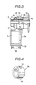
- FIG. 3 shows a spring clutch according to the present invention.
- reference numeral 10 denotes a frame which supports the output shaft 2 of a hollow construction.
- This output shaft 2 is to be coaxially connected to the driven part of a mechanism such as the photoconductive drum of a laser printer, and the paper feeding roller of a copying machine.
- the output shaft 2 includes one end portion 14 and the other end portion 18.
- the one end portion 14 of the output shaft 2 is held by the upper portion of the frame 10 through a bushing 16.
- the other end portion 18 of the output shaft 2 has a smaller outer diameter than the one end portion 14.
- An input shaft 20, i.e., a generally ring-shaped timing pulley fits slidably around the other end portion 18 for rotation about the output shaft 2.
- This pulley 20 is to be connected through a belt to the driving part of a mechanism such as a drive motor.
- the pulley 20 includes a boss portion 22 adjacent to the one end portion 14 of the output shaft 2.
- the boss portion has an equal outer diameter to that of the one end portion 14 of the output shaft 2.
- the coil spring 3 fits around both the one end portion 14 of the output shaft 2 and the boss portion 22 of the pulley 20.
- the one end 24 of this coil spring 3 is attached to the output shaft 2, while the other end 26 of the spring 3 is attached to a controlling collar 28 which fits around the coil spring 3.
- this controlling collar 28 is provided on its outer face with two engaging projections 30 and 32 disposed at 180° angular intervals about its axis.
- Each engaging projection has a relatively smaller axial width in comparison with the axial length of the controlling collar 28, and is positioned at generally intermediate portion of the controlling collar 28.
- a locking arm 34 is vertically disposed and is connected at its lower end to that portion of the frame 10 directly under the controlling collar 28, for axial pivotal movement relative to the controlling collar 28.
- the solenoid 5, i.e., an electromagnet is attached to the lower portion of the frame 10 so that it is arranged between the frame 10 and the locking arm 34 with its axis parallel to the axis of the input and output shafts 2 and 20.
- a spring 36 is disposed between the frame 10 and the lower end of the locking arm 34 in order to urge the locking arm 34 away from the solenoid 5.
- a stopper 38 is attached to the frame 10 for restricting the pivotal movement of locking arm 34.
- the rotation of the pulley 20 causes the coil spring 3 to reduce its inner diameter and to firmly grasp both the pulley 20 and the output shaft 2.
- the pulley 20 and the output shaft 2 are drivingly connected to each other through the coil spring 3 so that a torque of the pulley 20 is transferred to the output shaft 2.
- the locking arm 34 is attracted to the solenoid 5, and thereby pivoted into the position shown by the phantom line in FIG. 3 to contact with the solenoid 5.
- the upper end of the locking arm 34 is in the locus of the engaging projections 30 and 32 of the controlling collar 28. Therefore, the rotation of the pulley 20 causes a collision between the locking arm 34 and either of the projections 30 and 32 of the controlling collar 28, and further causes the projection which has had the collision to engage with the locking arm 34.
- the controlling collar 28 is rotated slightly in the reverse direction to the direction in which the pulley 20 is rotated, which causes the coil spring 3 to increase its diameter.
- the coil spring 3 loosens its grasp on the shafts 2 and 20 so that the shafts 2 and 20 are drivingly disconnected from each other. In spite of the rotation of the pulley 20, as long as the controlling collar 28 is locked, the coil spring 3 does not wind around the shafts 2 and 20.
- the locking arm 34 is disposed vertically, it may be disposed in any direction. Also, instead of the two projections 30 and 32, the controlling collar may be provided with only one or more than two projections.
Landscapes
- Engineering & Computer Science (AREA)
- General Engineering & Computer Science (AREA)
- Physics & Mathematics (AREA)
- Electromagnetism (AREA)
- Mechanical Engineering (AREA)
- Mechanical Operated Clutches (AREA)
Priority Applications (2)
| Application Number | Priority Date | Filing Date | Title |
|---|---|---|---|
| DE8787302616T DE3770810D1 (de) | 1987-03-26 | 1987-03-26 | Federkupplung. |
| EP19870302616 EP0287717B1 (de) | 1987-03-26 | 1987-03-26 | Federkupplung |
Applications Claiming Priority (1)
| Application Number | Priority Date | Filing Date | Title |
|---|---|---|---|
| EP19870302616 EP0287717B1 (de) | 1987-03-26 | 1987-03-26 | Federkupplung |
Publications (2)
| Publication Number | Publication Date |
|---|---|
| EP0287717A1 true EP0287717A1 (de) | 1988-10-26 |
| EP0287717B1 EP0287717B1 (de) | 1991-06-12 |
Family
ID=8197836
Family Applications (1)
| Application Number | Title | Priority Date | Filing Date |
|---|---|---|---|
| EP19870302616 Expired EP0287717B1 (de) | 1987-03-26 | 1987-03-26 | Federkupplung |
Country Status (2)
| Country | Link |
|---|---|
| EP (1) | EP0287717B1 (de) |
| DE (1) | DE3770810D1 (de) |
Cited By (1)
| Publication number | Priority date | Publication date | Assignee | Title |
|---|---|---|---|---|
| EP0638740A1 (de) * | 1993-08-05 | 1995-02-15 | Dana Corporation | Magnetischer - Flussbrecher für ein Solenoid in einer Schlingfeder - Kupplung |
Citations (4)
| Publication number | Priority date | Publication date | Assignee | Title |
|---|---|---|---|---|
| US3521730A (en) * | 1968-06-21 | 1970-07-28 | Precision Specialties Inc | Clutch brake having positive output position selection |
| US3905458A (en) * | 1974-06-26 | 1975-09-16 | Marquette Metal Products Co | Electro-magnetically actuated spring clutch |
| US3970175A (en) * | 1975-09-02 | 1976-07-20 | Marquette Metal Products Company | Support for an actuating arm of a control element of a spring clutch |
| GB2013795A (en) * | 1977-10-13 | 1979-08-15 | Lewis Spring Products Ltd | Electromagnetically controlled clutches |
-
1987
- 1987-03-26 DE DE8787302616T patent/DE3770810D1/de not_active Expired - Lifetime
- 1987-03-26 EP EP19870302616 patent/EP0287717B1/de not_active Expired
Patent Citations (4)
| Publication number | Priority date | Publication date | Assignee | Title |
|---|---|---|---|---|
| US3521730A (en) * | 1968-06-21 | 1970-07-28 | Precision Specialties Inc | Clutch brake having positive output position selection |
| US3905458A (en) * | 1974-06-26 | 1975-09-16 | Marquette Metal Products Co | Electro-magnetically actuated spring clutch |
| US3970175A (en) * | 1975-09-02 | 1976-07-20 | Marquette Metal Products Company | Support for an actuating arm of a control element of a spring clutch |
| GB2013795A (en) * | 1977-10-13 | 1979-08-15 | Lewis Spring Products Ltd | Electromagnetically controlled clutches |
Cited By (1)
| Publication number | Priority date | Publication date | Assignee | Title |
|---|---|---|---|---|
| EP0638740A1 (de) * | 1993-08-05 | 1995-02-15 | Dana Corporation | Magnetischer - Flussbrecher für ein Solenoid in einer Schlingfeder - Kupplung |
Also Published As
| Publication number | Publication date |
|---|---|
| EP0287717B1 (de) | 1991-06-12 |
| DE3770810D1 (de) | 1991-07-18 |
Similar Documents
| Publication | Publication Date | Title |
|---|---|---|
| US5052534A (en) | Electromagnetic synchronizing and shifting clutch | |
| JPS6053210B2 (ja) | 電磁クラツチ | |
| US4850418A (en) | Brake release mechanism for motor operated roller blinds and shutters | |
| CN100553076C (zh) | 齿轮传动电机 | |
| EP0287717A1 (de) | Federkupplung | |
| US2140975A (en) | Clutch mechanism | |
| EP0242982B1 (de) | Elektromagnetisch betätigter Federkupplungsmechanismus | |
| US4516764A (en) | Paper feeding device | |
| US4059176A (en) | Unitary spring clutch brake and actuator assembly | |
| US4905805A (en) | Torque limiting clutch with by-pass | |
| US5711405A (en) | Spring clutch mechanism and a clutch mechanism for use in a paper feeding apparatus | |
| US5335760A (en) | Magnetic flux breaker for a solenoid in a wrap spring clutch | |
| EP0374768B1 (de) | Schaltbare Federkupplungseinheit | |
| JPS6388327A (ja) | 電磁制御ばねクラツチ機構 | |
| US5129868A (en) | Quick-return motion mechanism of automatic magnetic drilling machine | |
| US11507011B2 (en) | Partial reverse clutch assembly | |
| US3570639A (en) | Solenoid-operated spring clutch | |
| EP0285244B1 (de) | Elektromagnetisch betätigter Federkupplungsmechanismus | |
| JPH0645063Y2 (ja) | 電磁制御ばねクラッチ機構 | |
| JP3592752B2 (ja) | 動力伝達切換え装置 | |
| JP3973099B2 (ja) | 画像形成装置 | |
| US20230143955A1 (en) | Stateful clutch system and methods | |
| JPH0628395U (ja) | クラッチ | |
| JP3321215B2 (ja) | 自動給紙装置 | |
| EP0884492A1 (de) | Kupplungsbefestigungsanordnung |
Legal Events
| Date | Code | Title | Description |
|---|---|---|---|
| PUAI | Public reference made under article 153(3) epc to a published international application that has entered the european phase |
Free format text: ORIGINAL CODE: 0009012 |
|
| 17P | Request for examination filed |
Effective date: 19880303 |
|
| AK | Designated contracting states |
Kind code of ref document: A1 Designated state(s): DE FR GB NL |
|
| 17Q | First examination report despatched |
Effective date: 19890210 |
|
| GRAA | (expected) grant |
Free format text: ORIGINAL CODE: 0009210 |
|
| AK | Designated contracting states |
Kind code of ref document: B1 Designated state(s): DE FR GB NL |
|
| REF | Corresponds to: |
Ref document number: 3770810 Country of ref document: DE Date of ref document: 19910718 |
|
| ET | Fr: translation filed | ||
| PGFP | Annual fee paid to national office [announced via postgrant information from national office to epo] |
Ref country code: FR Payment date: 19920227 Year of fee payment: 6 |
|
| PGFP | Annual fee paid to national office [announced via postgrant information from national office to epo] |
Ref country code: GB Payment date: 19920312 Year of fee payment: 6 |
|
| PGFP | Annual fee paid to national office [announced via postgrant information from national office to epo] |
Ref country code: NL Payment date: 19920331 Year of fee payment: 6 |
|
| PLBE | No opposition filed within time limit |
Free format text: ORIGINAL CODE: 0009261 |
|
| STAA | Information on the status of an ep patent application or granted ep patent |
Free format text: STATUS: NO OPPOSITION FILED WITHIN TIME LIMIT |
|
| PGFP | Annual fee paid to national office [announced via postgrant information from national office to epo] |
Ref country code: DE Payment date: 19920529 Year of fee payment: 6 |
|
| 26N | No opposition filed | ||
| PG25 | Lapsed in a contracting state [announced via postgrant information from national office to epo] |
Ref country code: GB Effective date: 19930326 |
|
| PG25 | Lapsed in a contracting state [announced via postgrant information from national office to epo] |
Ref country code: NL Effective date: 19931001 |
|
| NLV4 | Nl: lapsed or anulled due to non-payment of the annual fee | ||
| GBPC | Gb: european patent ceased through non-payment of renewal fee |
Effective date: 19930326 |
|
| PG25 | Lapsed in a contracting state [announced via postgrant information from national office to epo] |
Ref country code: FR Effective date: 19931130 |
|
| PG25 | Lapsed in a contracting state [announced via postgrant information from national office to epo] |
Ref country code: DE Effective date: 19931201 |
|
| REG | Reference to a national code |
Ref country code: FR Ref legal event code: ST |