EP0287725B1 - Procédé pour mesurer des propriétés de feuilles ayant une faible conductivité électrique - Google Patents
Procédé pour mesurer des propriétés de feuilles ayant une faible conductivité électrique Download PDFInfo
- Publication number
- EP0287725B1 EP0287725B1 EP87303579A EP87303579A EP0287725B1 EP 0287725 B1 EP0287725 B1 EP 0287725B1 EP 87303579 A EP87303579 A EP 87303579A EP 87303579 A EP87303579 A EP 87303579A EP 0287725 B1 EP0287725 B1 EP 0287725B1
- Authority
- EP
- European Patent Office
- Prior art keywords
- measured
- sheet
- resonator
- measurement
- resonant
- Prior art date
- Legal status (The legal status is an assumption and is not a legal conclusion. Google has not performed a legal analysis and makes no representation as to the accuracy of the status listed.)
- Expired
Links
- 239000000463 material Substances 0.000 title claims abstract description 54
- 238000000034 method Methods 0.000 title claims abstract description 10
- 239000004020 conductor Substances 0.000 claims abstract description 42
- 230000001419 dependent effect Effects 0.000 claims abstract description 8
- 230000005540 biological transmission Effects 0.000 claims abstract description 6
- 238000005259 measurement Methods 0.000 description 35
- 239000011120 plywood Substances 0.000 description 7
- 230000035945 sensitivity Effects 0.000 description 7
- 230000000694 effects Effects 0.000 description 5
- 230000005684 electric field Effects 0.000 description 5
- 239000011888 foil Substances 0.000 description 5
- 230000005855 radiation Effects 0.000 description 5
- 238000010276 construction Methods 0.000 description 3
- 230000008878 coupling Effects 0.000 description 3
- 238000010168 coupling process Methods 0.000 description 3
- 238000005859 coupling reaction Methods 0.000 description 3
- 230000003247 decreasing effect Effects 0.000 description 3
- 238000006073 displacement reaction Methods 0.000 description 3
- 238000004519 manufacturing process Methods 0.000 description 2
- 238000000691 measurement method Methods 0.000 description 2
- 230000000149 penetrating effect Effects 0.000 description 2
- 125000006850 spacer group Chemical group 0.000 description 2
- 238000013459 approach Methods 0.000 description 1
- 229920002678 cellulose Polymers 0.000 description 1
- 239000001913 cellulose Substances 0.000 description 1
- 238000007796 conventional method Methods 0.000 description 1
- 238000001035 drying Methods 0.000 description 1
- -1 e.g. Substances 0.000 description 1
- 231100001261 hazardous Toxicity 0.000 description 1
- 239000012212 insulator Substances 0.000 description 1
- 230000005865 ionizing radiation Effects 0.000 description 1
- 238000007493 shaping process Methods 0.000 description 1
- 238000010408 sweeping Methods 0.000 description 1
- 238000012546 transfer Methods 0.000 description 1
- 239000002023 wood Substances 0.000 description 1
Images


Classifications
-
- G—PHYSICS
- G01—MEASURING; TESTING
- G01N—INVESTIGATING OR ANALYSING MATERIALS BY DETERMINING THEIR CHEMICAL OR PHYSICAL PROPERTIES
- G01N22/00—Investigating or analysing materials by the use of microwaves or radio waves, i.e. electromagnetic waves with a wavelength of one millimetre or more
- G01N22/04—Investigating moisture content
Definitions
- the present invention concerns a method for determining properties of planar or foil-like materials of high moisture content and low electrical conductivity.
- the transducers used are mainly of a contacting type, such as humidity sensors for plywood, based on resistance measurement, or sheet basis weight measuring scales.
- the contacting transducers e.g. capacitive sensors
- the contacting transducers are susceptible to a high measurement error by the vertical movement of the material.
- Transducers based on penetrating radiation such as gamma rays, often have a slow response, are expensive, and, furthermore, are hazardous due to *he ionizing radiation utilized.
- a non- penetrating radiation such as infrared radiation, delivers only superficial information from the immediate surface of the material.
- DE-A 2 340 130 discloses the use of TE modes whose resonance frequencies and Q's are dependent on the properties of the material while GB-A 1 520 894 discloses the use of two resonator halves excited in TE modes in order to determine the change of resonant frequency and loses caused by a sheet of material, that is, the dielectric Qc.
- the movement of the sheet or foil relative to the transducer often causes lare errors in measurement since, in the measurement of thin sheets or foils, the transducer must be brought close enough to the material to obtain a sufficiently strong signal.
- the aim of this invention is to overcome the drawbacks of the above described technique and to provide a novel measurement method for the determination of characteristics in sheet- or foil-like materials of low electrical conductivity and high moisture content.
- the invention is based on the use of a transducer which consists of parts located at both sides of the material, which together form an electromagnetic quasi-TEM transmission line resonator with several center conductors.
- the construction supports several resonant wave modes, whose Q and resonant frequency are dependent on the material since its dielectric constant differs from that of air. By selecting an appropriate mode, these measurement signals can be maximized while the effect of material movement on the signals is minimized.
- the measurement method in accordance with the invention operating in the RF range can be used for the concurrent determination of one or more properties of a sheet-or foil-like material.
- the material may be any material of low electrical conductivity, such as plywood sheet, plastic or cellulose seeet, or paper web. The material passes through the transducer without contacting it, which facilitates a rapid automatic measurement, and even relatively large displacements perpendicular to the plane of the material sheet or foil do not appreciably affect the measurement result.
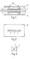
- Transducers applicable to the measurement of characteristics of sheet-or foil-like materials having low electrical conductivity in accordance with a method embodying the invention are shown in Figures 1 to 5.
- the transducer illustrated in the figures is comprised of two ground planes 3 and, in this example, of two center conductors 2 (strip, pipe, etc.) as well as insulator spacers 4 used for supporting the center conductors.
- the material 1 to be measured is located to the middle of the center conductors so that the material plane is parallel to the ground plane.
- the ground planes and the center conductors together form an electromagnetic resonator, in which the electromagnetic wave propagates parallel to the level of the material to be measured.
- the resonator illustrated in Figures 1 and 2 is resonant when the wavelength is twice the length of the center conductors 2.
- the dielectric sheet between the center conductors 2 alters the wavelength and, consequently, also the resonant frequency of the construction.
- the material also attenuates the fields, which can be detected from the change of the resonator Q.
- Information from the characteristics of the resonance can be obtained by connecting the resonator to a measurement circuit via coupling pins or loops 5.
- Quasi-TEM transmission line resonators with several center conductors such as the resonator illustrated in Figures 1...5, support several resonant modes at different potential combinations of center conductors.
- the resonator with two center conductors the situation can be described as the resonator supporting an even mode with the center conductors being equipotential and an odd mode with the center conductors having opposite potentials. Due to slightly different discontinuity capacitances, the resonant frequencies of the even and odd modes of same order are generally slightly displaced.
- the field patterns are distinctly different in the plane orthogonal to the wave propagation direction of the even and odd resonant mode.
- the electric field pattern of the even mode is shown in Figure 4, and the corresponding electric field pattern of the odd mode in Figure 5. It can be seen in the figures that when the thin sheet or foil to be measured is located to the middle of the center conductors 2, the electric field at the location of the sheet to be measured is parallel to the plane of the sheet 1 for the even mode while being orthogonal to the sheet 1 for the odd mode. Hence, the relative changes in the resonant frequency and Q of the resonator caused by the sheet to be measured, compared to the unloaded resonator, are distinctly higher with the even mode than with the odd mode.
- the vertical axis is the relative change of resonant frequency and the horizontal axis is the displacement of the sheet position from the midpoint of the transducer.
- the dimension A of the transducer shown in the figure is typically 100 mm, dimension B is 125 mm, and dimension C is 100 mm.
- the parameter calculated from the lift side of the equation is not dependent on the thickness of the material sheet, such as plywood. Furthermore, the parameter is generally dependent only to a minor extent on the material density. However, the parameter is dependent on the moisture content of the material, e.g., wood, which offers a method for determining the moisture content.
- Both the resonant frequency and the measurement range of the transducer can be influenced by the shape of the center conductors 2 of the resonator.
- a star center conductor with a butterfly-shaped cross section in accordance with Figure 3 results in a resonant frequency which is half that of a strip-shaped center conductor with the same length.
- the lower resonant frequency allows, for instance, a wider distance between the center conductors, resulting in lower sensitivity to the vertical movement of the material.
- the measurement area of the transducer extends outside the edges of the center conductors to a distance approximately one-third of the mutual distance between the center conductors, thus resulting in a shorter and wider area of measurement for the butterfly-shaped center conductors compared to the strip-shaped center conductors of constant width.
- the center conductors 2 illustrated in Figures 1 to 5 are electrically open-circuited at both ends. However, the center conductors 2 can be short-circuited at both ends or at either end to the ground plane 3 without significantly altering their operation.
- the ground planes 3 must extend in the cross direction by at least a third-wavelength outside the edges of the center conductors to prevent radiation from the resonator.
- the resonant frequency and Q can be measured at least 50 times a second, which facilitates the determination of properties in a relatively fast moving material.
- the measurement area of the transducer can be influenced, facilitating a focused determination of material properties.
- the facilities are important, for instance, in determining moisture content in plywood sheets because the sheet is thin; when dry, its dielectric constant is close to that of air; and after drying, the sheet is often extremely undulated.
- the changes in resonant frequency caused by the material 1 to be measured are different for the different resonant modes.
- the frequency change for the even mode is directly proportional to the parameter C r-1, and for the odd mode, to the parameter (cr1)/c ⁇ ' (refer to Figure 7).
- the real part of the dielectric constant cr is also high.
- small changes in moisture content of the wet material 1 cause no significant frequency change for the odd mode. Since, by contrast, the resonant frequency change for the even mode is appreciable, the effect of error factors can be compensated for.
- Such error factors are, for instance, the vertical movement of the measured object 1 relative to the transducer, changes in the mutual distance between the center conductors 2, and dimensional changes of the transducer parts due to temperature changes. If the moisture content of the material to be measured is high and the variations in moisture content are small, the aforementioned measurement error can be reduced. To reduce the measurement errors, the resonant frequencies of both resonant modes can be measured simultaneously. Then, the different resonant modes can be distinguished in the measurement setup from the different resonant frequencies characteristic of the modes. The error compensation can be simply performed by subtracting the resonant frequencies of the modes from each other. However, the compensation is not complete because the effect of error sources on the resonant frequencies of the different modes is not equal.
- the effectiveness of compensation depends on how well the effect of the error sources can be arranged equal on the different resonant modes. By choosing the mutual distance between the center conductors 2 and the spacing of the ground planes 3 from the center conductors 2 appropriately, the effect of error sources can be decreased significantly.
- error in measurement of paper moisture content was reduced to one-third by compensation when the distance between the center conductors 2 was chosen as 5 cm, and the spacing of the ground planes 3 from the center conductors 2 was chosen as 6 cm.
- the moisture content of paper was 58 % on the average, and its variation range was ⁇ 2.5 %-units.
- the measurement frequencies used were in the order of 350 MHz.
- Information from the characteristics of the resonance is obtained by feeding the RF signal to coupling pins 5 or corresponding coupling loops, and then measuring the resonant frequencies.
- the resonant frequencies are found by, for instance, sweeping over the frequency range of the resonator and then determining the amplitude maxima of the signal.
Landscapes
- Physics & Mathematics (AREA)
- Electromagnetism (AREA)
- Health & Medical Sciences (AREA)
- Life Sciences & Earth Sciences (AREA)
- Chemical & Material Sciences (AREA)
- Analytical Chemistry (AREA)
- Biochemistry (AREA)
- General Health & Medical Sciences (AREA)
- General Physics & Mathematics (AREA)
- Immunology (AREA)
- Pathology (AREA)
- Measurement Of Resistance Or Impedance (AREA)
- Investigating Or Analyzing Materials By The Use Of Electric Means (AREA)
Claims (1)
- Procédé pour mesurer des propriétés de matériaux (1) en forme de feuilles ou de pellicules, ayant une forte teneur en humidité et une faible conductivité électrique, caractérisé en ce qu'il comprend la disposition de plans de masse (3) des deux côtés du matériau (1) à mesurer; la disposition d'au moins un conducteur central (2) entre chaque plan de masse (3) et le matériau (1) à mesurer, à peu près parallèlement au matériau (1 de manière à former un résonateur de ligne de transmission quasi-TEM; l'alimentation de ce résonateur en énergie électromagnétique radiofréquence, de manière que les modes quasi-TEM se propagent parallèlement au matériau (1) à mesurer et que le résonateur soutienne des modes résonnants à la fois des modes transversaux et des modes longitudinaux dont les fréquences de résonance et les facteurs Q dépendent des propriétés du matériau (1) à mesurer; de même que la mesure des fréquences de résonance et des Q qui s'y rapportent, les fréquences de résonance d'au moins deux modes résonnants étant mesurées sensiblement en même temps et la différence entre au moins deux fréquences de résonance étant déterminée pour représenter la valeur d'humidité proportionnelle à celle du matériau (1) à mesurer.
Priority Applications (5)
| Application Number | Priority Date | Filing Date | Title |
|---|---|---|---|
| FI854202A FI74816C (fi) | 1985-10-28 | 1985-10-28 | Maetningsfoerfarande och -apparat foer beroeringsfri maetning av daoligt elektricitet ledande skiv- eller folieformade materials elektriska egenskaper eller dessa paoverkande elektriska egenskaper. |
| AT87303579T ATE55648T1 (de) | 1987-04-23 | 1987-04-23 | Verfahren zur messung von eigenschaften von schwach elektrischleitenden blatt- oder folienartigen materialien. |
| ES87303579T ES2018019B3 (es) | 1987-04-23 | 1987-04-23 | Metodo y aparato para medir propiedades de chapas o materiales en forma de hojas de baja conductividad electrica |
| DE8787303579T DE3764363D1 (de) | 1987-04-23 | 1987-04-23 | Verfahren zur messung von eigenschaften von schwach elektrischleitenden blatt- oder folienartigen materialien. |
| EP87303579A EP0287725B1 (fr) | 1987-04-23 | 1987-04-23 | Procédé pour mesurer des propriétés de feuilles ayant une faible conductivité électrique |
Applications Claiming Priority (1)
| Application Number | Priority Date | Filing Date | Title |
|---|---|---|---|
| EP87303579A EP0287725B1 (fr) | 1987-04-23 | 1987-04-23 | Procédé pour mesurer des propriétés de feuilles ayant une faible conductivité électrique |
Publications (2)
| Publication Number | Publication Date |
|---|---|
| EP0287725A1 EP0287725A1 (fr) | 1988-10-26 |
| EP0287725B1 true EP0287725B1 (fr) | 1990-08-16 |
Family
ID=8197877
Family Applications (1)
| Application Number | Title | Priority Date | Filing Date |
|---|---|---|---|
| EP87303579A Expired EP0287725B1 (fr) | 1985-10-28 | 1987-04-23 | Procédé pour mesurer des propriétés de feuilles ayant une faible conductivité électrique |
Country Status (4)
| Country | Link |
|---|---|
| EP (1) | EP0287725B1 (fr) |
| AT (1) | ATE55648T1 (fr) |
| DE (1) | DE3764363D1 (fr) |
| ES (1) | ES2018019B3 (fr) |
Families Citing this family (5)
| Publication number | Priority date | Publication date | Assignee | Title |
|---|---|---|---|---|
| DE102007025815A1 (de) * | 2007-06-02 | 2008-12-04 | Voith Patent Gmbh | Verfahren und Vorrichtung zur Messung wenigstens einer Qualitätsgröße einer Faserstoffbahn |
| DE102007029908A1 (de) | 2007-06-28 | 2009-01-02 | Tews Elektronik Dipl.-Ing. Manfred Tews | Vorrichtung und Verfahren zur Masse- und/oder Feuchtemessung von dielektrischen Objekten |
| DE202007018481U1 (de) * | 2007-08-28 | 2008-09-11 | Tews Elektronik Dipl.-Ing. Manfred Tews | Vorrichtung zur Messung eines Feuchtewertes von dielektrischen Stoffen |
| DE102008018888B4 (de) * | 2008-04-14 | 2014-03-13 | Elisabeth Katz | Vorrichtung zur Bestimmung des Feuchtegehalts einer Materialbahn oder -platte |
| GB202001568D0 (en) * | 2020-02-05 | 2020-03-18 | Medical Wireless Sensing Ltd | Metamaterial device |
Family Cites Families (6)
| Publication number | Priority date | Publication date | Assignee | Title |
|---|---|---|---|---|
| GB1106185A (en) * | 1964-05-29 | 1968-03-13 | Nils Bertil Agdur | Device for measuring a property of a material |
| GB1030834A (en) * | 1965-02-11 | 1966-05-25 | Kenneth Edney Hancock | Method and apparatus for measurement of moisture content |
| US3460031A (en) * | 1966-06-08 | 1969-08-05 | Industrial Nucleonics Corp | Microwave waveguide moisture measurement |
| DE2340130C3 (de) * | 1973-08-08 | 1979-08-09 | Bayer Ag, 5090 Leverkusen | Verfahren zur Bestimmung des Wassergehaltes von dünnen, flächenhaften Materialien |
| GB1520894A (en) * | 1976-06-28 | 1978-08-09 | Bilbrough J | Moisture measuring apparatus |
| DE3133012A1 (de) * | 1981-08-20 | 1983-03-10 | Siemens AG, 1000 Berlin und 8000 München | Vorrichtung zur messung des feuchtigkeitsgehalts bahn- und zylinderfoermiger, elektrisch nichtleitender materialien |
-
1987
- 1987-04-23 ES ES87303579T patent/ES2018019B3/es not_active Expired - Lifetime
- 1987-04-23 AT AT87303579T patent/ATE55648T1/de not_active IP Right Cessation
- 1987-04-23 EP EP87303579A patent/EP0287725B1/fr not_active Expired
- 1987-04-23 DE DE8787303579T patent/DE3764363D1/de not_active Expired - Lifetime
Also Published As
| Publication number | Publication date |
|---|---|
| EP0287725A1 (fr) | 1988-10-26 |
| ES2018019B3 (es) | 1991-03-16 |
| ATE55648T1 (de) | 1990-09-15 |
| DE3764363D1 (de) | 1990-09-20 |
Similar Documents
| Publication | Publication Date | Title |
|---|---|---|
| US4739249A (en) | Method and apparatus for the measurement of the properties of sheet- or foil-like materials of low electrical conductivity | |
| US5334941A (en) | Microwave reflection resonator sensors | |
| CN110375686B (zh) | 用于金属结构裂纹和应变监测的无线柔性微带贴片天线传感器阵列 | |
| US4890054A (en) | Apparatus and method for measuring physical quantities | |
| US7151380B2 (en) | Microwave water weight sensor and process | |
| Tanabe et al. | A nondestructive method for measuring the complex permittivity of dielectric materials at microwave frequencies using an open transmission line resonator | |
| US3829764A (en) | Method and apparatus for measuring physical and/or chemical properties of materials | |
| JPH01131401A (ja) | 移動シート材料用走査型厚さ計兼水分計 | |
| KR20060052901A (ko) | 수분량 측정 방법 및 장치 | |
| EP0287725B1 (fr) | Procédé pour mesurer des propriétés de feuilles ayant une faible conductivité électrique | |
| US3460031A (en) | Microwave waveguide moisture measurement | |
| US6930492B2 (en) | Using surface microwaves for measuring and determining density and/or moisture content of a material | |
| US3710243A (en) | Microwave gage for monitoring thickness of a conductive workpiece, flaws therein or displacement relative thereto | |
| EP1703275A1 (fr) | Appareil et procédé pour déterminer le grammage de papier ou la densité de pulpe pendant la fabrication de papier en utlisant des micro ondes | |
| JPH0229982B2 (fr) | ||
| CA1263442A (fr) | Methode et appareil de mesure des proprietes hygrometriques de materiaux en feuille a faible conductivite electrique | |
| CA2691525C (fr) | Dispositif de mesure de l'epaisseur d'une couche de materiau | |
| US8188751B2 (en) | Method and measuring instrument for measuring water content | |
| FI74816C (fi) | Maetningsfoerfarande och -apparat foer beroeringsfri maetning av daoligt elektricitet ledande skiv- eller folieformade materials elektriska egenskaper eller dessa paoverkande elektriska egenskaper. | |
| CN115290700B (zh) | 一种基于开口谐振器慢波结构的金属裂纹检测装置和方法 | |
| Bozzi et al. | A planar applicator for measuring surface dielectric constant of materials | |
| Fischer et al. | Fast moisture profile mapping of a wet paper web with a dual-mode resonator array | |
| RU2321010C1 (ru) | Устройство для измерения больших значений комплексной диэлектрической проницаемости низкоимпедансных композиционных материалов на свч | |
| FI73084B (fi) | Maetmetod och -apparat foer maetning av egenskaperna av ett materieskikt vars elektriska konduktivitet aer laog | |
| JPH0658331B2 (ja) | 平面状材料の物性量測定装置 |
Legal Events
| Date | Code | Title | Description |
|---|---|---|---|
| PUAI | Public reference made under article 153(3) epc to a published international application that has entered the european phase |
Free format text: ORIGINAL CODE: 0009012 |
|
| AK | Designated contracting states |
Kind code of ref document: A1 Designated state(s): AT BE CH DE ES FR GB GR IT LI LU NL SE |
|
| 17P | Request for examination filed |
Effective date: 19880622 |
|
| 17Q | First examination report despatched |
Effective date: 19890224 |
|
| GRAA | (expected) grant |
Free format text: ORIGINAL CODE: 0009210 |
|
| AK | Designated contracting states |
Kind code of ref document: B1 Designated state(s): AT BE CH DE ES FR GB GR IT LI LU NL SE |
|
| PG25 | Lapsed in a contracting state [announced via postgrant information from national office to epo] |
Ref country code: LI Effective date: 19900816 Ref country code: GR Free format text: LAPSE BECAUSE OF FAILURE TO SUBMIT A TRANSLATION OF THE DESCRIPTION OR TO PAY THE FEE WITHIN THE PRESCRIBED TIME-LIMIT Effective date: 19900816 Ref country code: CH Effective date: 19900816 |
|
| REF | Corresponds to: |
Ref document number: 55648 Country of ref document: AT Date of ref document: 19900915 Kind code of ref document: T |
|
| REF | Corresponds to: |
Ref document number: 3764363 Country of ref document: DE Date of ref document: 19900920 |
|
| ITF | It: translation for a ep patent filed | ||
| ET | Fr: translation filed | ||
| REG | Reference to a national code |
Ref country code: CH Ref legal event code: PL |
|
| PG25 | Lapsed in a contracting state [announced via postgrant information from national office to epo] |
Ref country code: LU Free format text: LAPSE BECAUSE OF NON-PAYMENT OF DUE FEES Effective date: 19910430 |
|
| PLBE | No opposition filed within time limit |
Free format text: ORIGINAL CODE: 0009261 |
|
| STAA | Information on the status of an ep patent application or granted ep patent |
Free format text: STATUS: NO OPPOSITION FILED WITHIN TIME LIMIT |
|
| 26N | No opposition filed | ||
| ITTA | It: last paid annual fee | ||
| PGFP | Annual fee paid to national office [announced via postgrant information from national office to epo] |
Ref country code: ES Payment date: 19930318 Year of fee payment: 7 |
|
| PGFP | Annual fee paid to national office [announced via postgrant information from national office to epo] |
Ref country code: GB Payment date: 19930414 Year of fee payment: 7 |
|
| PGFP | Annual fee paid to national office [announced via postgrant information from national office to epo] |
Ref country code: BE Payment date: 19930415 Year of fee payment: 7 |
|
| PGFP | Annual fee paid to national office [announced via postgrant information from national office to epo] |
Ref country code: NL Payment date: 19930430 Year of fee payment: 7 |
|
| PG25 | Lapsed in a contracting state [announced via postgrant information from national office to epo] |
Ref country code: GB Effective date: 19940423 |
|
| PG25 | Lapsed in a contracting state [announced via postgrant information from national office to epo] |
Ref country code: ES Free format text: LAPSE BECAUSE OF NON-PAYMENT OF DUE FEES Effective date: 19940425 |
|
| PG25 | Lapsed in a contracting state [announced via postgrant information from national office to epo] |
Ref country code: BE Effective date: 19940430 |
|
| BERE | Be: lapsed |
Owner name: IMATRAN VOIMA OY Effective date: 19940430 |
|
| PG25 | Lapsed in a contracting state [announced via postgrant information from national office to epo] |
Ref country code: NL Effective date: 19941101 |
|
| NLV4 | Nl: lapsed or anulled due to non-payment of the annual fee | ||
| GBPC | Gb: european patent ceased through non-payment of renewal fee |
Effective date: 19940423 |
|
| EAL | Se: european patent in force in sweden |
Ref document number: 87303579.4 |
|
| REG | Reference to a national code |
Ref country code: ES Ref legal event code: FD2A Effective date: 19990503 |
|
| PG25 | Lapsed in a contracting state [announced via postgrant information from national office to epo] |
Ref country code: IT Free format text: LAPSE BECAUSE OF NON-PAYMENT OF DUE FEES;WARNING: LAPSES OF ITALIAN PATENTS WITH EFFECTIVE DATE BEFORE 2007 MAY HAVE OCCURRED AT ANY TIME BEFORE 2007. THE CORRECT EFFECTIVE DATE MAY BE DIFFERENT FROM THE ONE RECORDED. Effective date: 20050423 |
|
| PGFP | Annual fee paid to national office [announced via postgrant information from national office to epo] |
Ref country code: FR Payment date: 20060411 Year of fee payment: 20 |
|
| PGFP | Annual fee paid to national office [announced via postgrant information from national office to epo] |
Ref country code: SE Payment date: 20060413 Year of fee payment: 20 |
|
| PGFP | Annual fee paid to national office [announced via postgrant information from national office to epo] |
Ref country code: AT Payment date: 20060418 Year of fee payment: 20 |
|
| PGFP | Annual fee paid to national office [announced via postgrant information from national office to epo] |
Ref country code: DE Payment date: 20060419 Year of fee payment: 20 |
|
| EUG | Se: european patent has lapsed |