EP0287744A1 - Echange de courant à contact glissant - Google Patents
Echange de courant à contact glissant Download PDFInfo
- Publication number
- EP0287744A1 EP0287744A1 EP87630239A EP87630239A EP0287744A1 EP 0287744 A1 EP0287744 A1 EP 0287744A1 EP 87630239 A EP87630239 A EP 87630239A EP 87630239 A EP87630239 A EP 87630239A EP 0287744 A1 EP0287744 A1 EP 0287744A1
- Authority
- EP
- European Patent Office
- Prior art keywords
- contact element
- connector
- conductive surface
- housing
- contact
- Prior art date
- Legal status (The legal status is an assumption and is not a legal conclusion. Google has not performed a legal analysis and makes no representation as to the accuracy of the status listed.)
- Granted
Links
- 238000010791 quenching Methods 0.000 claims abstract description 6
- 229910052729 chemical element Inorganic materials 0.000 abstract 1
- 238000010276 construction Methods 0.000 description 3
- 239000004020 conductor Substances 0.000 description 2
- 239000000463 material Substances 0.000 description 2
- 230000007246 mechanism Effects 0.000 description 2
- 230000015556 catabolic process Effects 0.000 description 1
- 230000006835 compression Effects 0.000 description 1
- 238000007906 compression Methods 0.000 description 1
- 230000008030 elimination Effects 0.000 description 1
- 238000003379 elimination reaction Methods 0.000 description 1
- 238000010438 heat treatment Methods 0.000 description 1
- 238000009413 insulation Methods 0.000 description 1
- 230000013011 mating Effects 0.000 description 1
- 230000002028 premature Effects 0.000 description 1
Images
Classifications
-
- H—ELECTRICITY
- H01—ELECTRIC ELEMENTS
- H01R—ELECTRICALLY-CONDUCTIVE CONNECTIONS; STRUCTURAL ASSOCIATIONS OF A PLURALITY OF MUTUALLY-INSULATED ELECTRICAL CONNECTING ELEMENTS; COUPLING DEVICES; CURRENT COLLECTORS
- H01R13/00—Details of coupling devices of the kinds covered by groups H01R12/70 or H01R24/00 - H01R33/00
-
- H—ELECTRICITY
- H01—ELECTRIC ELEMENTS
- H01R—ELECTRICALLY-CONDUCTIVE CONNECTIONS; STRUCTURAL ASSOCIATIONS OF A PLURALITY OF MUTUALLY-INSULATED ELECTRICAL CONNECTING ELEMENTS; COUPLING DEVICES; CURRENT COLLECTORS
- H01R13/00—Details of coupling devices of the kinds covered by groups H01R12/70 or H01R24/00 - H01R33/00
- H01R13/46—Bases; Cases
- H01R13/53—Bases or cases for heavy duty; Bases or cases for high voltage with means for preventing corona or arcing
Definitions
- This invention relates to electrical connectors, and, more particularly, to separable electrical connectors suited for use under high voltage conditions.
- this invention relates to gas actuated high voltage bushings having a contact mounted within a bore for reciprocal movement within a bushing housing, such as that illustrated in U.S. Flatt Patent 4,099,155 issued July 4, 1978 and incorporated herein by reference.
- Electrical connectors such as that described in the above Flatt patent, have had a housing having a passage including an electrically conductive surface fixably secured within the housing, and a contact assembly disposed in the passage and movable relative to the housing conductive surface.
- Such devices have also included a contactor for providing electrical continuity between the contact assembly and the housing conductive surface.
- the contactor has often been in the form of a metallic louvered spring member encircling a portion of the contact assembly in an electrically conductive relationship with the contact assembly and the housing conductive surface.
- U.S. Flatt Patent 4,131,329 issued December 26, 1978 illustrates another type of contactor in the form of an annular compression spring received in an annular groove in the housing conductive surface.
- U.S. Tachick et al Patent 4,119,358 issued October 10, 1978 illustrates another type of contactor in the form of a sliding contact sleeve flared outwardly to resiliently engage the housing conductive surface.
- a problem inherent with these types of contactors is that the contactor is usually made of a material different than the contact assembly and the housing conductive surface. This increases the likelihood of having a poor current path between the housing conductive surface and the contact assembly, which can result in premature failure of the connector due to high resistance hot spots causing insulation breakdown. Further, the need for providing a separate member increases the cost of the product.
- Electrical connectors of this type have also usually included additional mechanical mechanisms for facilitating threaded engagement of different portions of the contact assembly when the connector is assembled.
- slot and key arrangements have been used to prevent rotation of the contact assembly relative to the housing. See, for example, elements 44 and 50h in the Stanger et al Patent 3,930,709.
- a mating or serrated teeth arrangement has been provided on one end of the contact assembly for engaging the housing conductive surface when the contact assembly is in a particular position. When the contact assembly is moved from this position, the teeth no longer engage.
- One of the principal features of this invention is the provision of an electrical connector which includes an improved contactor for providing electrical continuity between the contact assembly and the housing conductive surface.
- Another of the principal features of the invention is the provision of such a contactor which eliminates the need for a slot and key or teeth arrangement or other separate mechanism for facilitating threaded engagement of separate portions of the contact assembly by preventing rotation of the contact assembly relative to the housing.
- This invention provides an electrical device comprising a housing having a passage including an electrically conductive surface fixably secured within the housing, and a contact assembly disposed in the passage and movable relative to the housing conductive surface.
- the contact assembly includes a member having a conductive surface, and one of the housing conductive surface and the member conductive surface has a knurl in contact with the other of the housing conductive surface and the member conductive surface so that there is continuous electrical continuity between the contact assembly and the housing conductive surface.
- the knurl is on the contact assembly member.
- the knurl on the member conductive surface eliminates one of the conductor to conductor current interchanges found in the prior art constructions. More particularly, in this embodiment, the current interchange between the contactor and the movable contact has been eliminated. This elimination of this interchange reduces the resistance of the current path which reduces heating of the assembly.
- This invention also provides a first connector for use in connecting or disconnecting a high voltage circuit by engagement or disengagement of the first connector with a second connector supporting a male contact member.
- the first connector comprises a housing having an axial passage including an electrically conductive surface fixedly secured within the housing, and a contact assembly disposed in the passage and including a female contact element for engaging the male contact element.
- the contact assembly includes guide means for guiding the male contact element for movement towards the female contact element and for evolving arc-quenching gas in response to an arc being struck between the female contact element and the male contact element.
- the contact assembly also includes piston means responsive to the evolved gas for displacing the contact assembly towards the male contact element, and contactor means electrically connected to the female contact element for providing electrical continuity between the female contact element and the housing conductive surface.
- the contactor means includes a member having a knurl in interference fit contact with the housing conductive surface.
- the piston means is the contactor member, and the contactor member is fixedly connected to the female contact element.
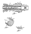
- this invention provides an electrical connector apparatus 10 comprising a first connector 14 electrically connected to a portion of a high voltage circuit (not shown) and a second connector 18 supporting a male contact element 22 electrically connected to another portion of the high voltage circuit. More particularly, the second connector 18 is in the form of a cable termination device such as an elbow. Only a portion of the second connector 18 is illustrated in FIG. 1.
- the first connector 14 is in the form of a bushing comprising an insulative housing 26 having two pieces 27 and 28 and having an axial passage 30 including an electrically conductive surface 34 fixedly secured within the housing 26. More particularly, the housing conductive surface 34 is provided by a shield assembly 38 including a tube shield 42 and a bushing assembly nose 46 threadably received within the tube shield 42.
- the first connector 14 also includes a contact assembly 50 slidably disposed in the passage 30 and including a female contact element 54 for engaging the male contact element 22.
- the contact assembly 50 also includes a retaining tube 58 which locates and holds the female contact element 54 in place. More particularly, the female contact element 54 has a rough outer surface which is engaged by the retaining tube 58. The female contact element 54 has a threaded base portion 62 and spaced apart fingers 66 for resiliently engaging the male contact element 22.
- the contact assembly 50 also includes guide means in the form of a guide tube 70 made of gas evolving material for guiding the male contact element 22 for movement towards the female contact element 54 and for evolving arc-quenching gas in response to an arc being struck between the female contact element 54 and the male contact element 22.
- the guide tube 70 is secured to the retaining tube 58 to the left (as shown in Fig. 1) of the female contact element 54, and a bushing nose assembly 72 is threaded into the retaining tube 58.
- the contact assembly 50 also includes piston means responsive to the evolved gas for displacing the contact assembly 50 towards the male contact element 22. More particularly, the piston means is in the form of a piston 74 having an inner threaded portion 78 which is threaded onto the outer threaded portion 62 of the female contact element 54.
- the gas pressure acts on the surface of the piston 74 and attempts to increase the size of the closed end of the axial passage 30 by moving the piston 74 toward the male contact element 22.
- the contact assembly 50 also includes contactor means 82 for providing electrical continuity between the female contact element 54 and the housing conductive surface 34 when the contact assembly 50 is stationary and when the female contact element 54 moves relative to the housing conductive surface 34. More particularly, the contactor means 82 is electrically connected to the female contact element 54.
- the contactor means 82 is the piston 74.
- the piston 74 has a conductive surface 86 and a knurl 90. More particularly, the piston knurl 90 is in interference contact with the housing conductive surface 34. As illustrated in FIGS. 2 and 3, the knurl 90 comprises a plurality of spaced peaks 94 extending radially outwardly in a band around the piston 74. The outer diameter of the knurl 90 is greater than the inner diameter of the housing conductive surface 34 defined by the tube shield 42.
- the knurl 90 on the piston 74 provides a good electrical current interchange between the female contact element 54 and the housing conductive surface 34, even as the contact assembly 50 moves relative to the housing conductive surface 34. Further, the knurl 90 holds the contact assembly 50 in interference contact with the housing conductive surface 34. This interference contact assists in the assembly of the contact assembly 50 and the housing 26 with the shield assembly 38. More particularly, the piston 74 can be located within the tube shield 42, where the knurl 90 will hold it in place, and the remainder of the contact assembly 50, including the retaining tube 58, the female contact element 54, the guide tube 70 and the nose assembly 72, can then be threaded into the piston 74.
- the contactor means 82 can be in the form of a member located between the piston 74 and the female contact element 54, and electrically connected to the female contact element 54.
Landscapes
- Connector Housings Or Holding Contact Members (AREA)
- Coupling Device And Connection With Printed Circuit (AREA)
- Glass Compositions (AREA)
- Superconductors And Manufacturing Methods Therefor (AREA)
- Pressure Welding/Diffusion-Bonding (AREA)
- Circuit Breakers (AREA)
- Cable Accessories (AREA)
- Details Of Connecting Devices For Male And Female Coupling (AREA)
Priority Applications (1)
| Application Number | Priority Date | Filing Date | Title |
|---|---|---|---|
| AT87630239T ATE93096T1 (de) | 1987-04-24 | 1987-11-17 | Stromaustausch mit schleifkontakt. |
Applications Claiming Priority (2)
| Application Number | Priority Date | Filing Date | Title |
|---|---|---|---|
| US41959 | 1987-04-24 | ||
| US07/041,959 US4713018A (en) | 1987-04-24 | 1987-04-24 | Sliding current interchange |
Publications (2)
| Publication Number | Publication Date |
|---|---|
| EP0287744A1 true EP0287744A1 (fr) | 1988-10-26 |
| EP0287744B1 EP0287744B1 (fr) | 1993-08-11 |
Family
ID=21919266
Family Applications (1)
| Application Number | Title | Priority Date | Filing Date |
|---|---|---|---|
| EP87630239A Expired - Lifetime EP0287744B1 (fr) | 1987-04-24 | 1987-11-17 | Echange de courant à contact glissant |
Country Status (9)
| Country | Link |
|---|---|
| US (1) | US4713018A (fr) |
| EP (1) | EP0287744B1 (fr) |
| JP (1) | JPH0812786B2 (fr) |
| KR (1) | KR950006021B1 (fr) |
| AT (1) | ATE93096T1 (fr) |
| AU (1) | AU603841B2 (fr) |
| CA (1) | CA1296402C (fr) |
| DE (1) | DE3787013T2 (fr) |
| MX (1) | MX162056A (fr) |
Families Citing this family (15)
| Publication number | Priority date | Publication date | Assignee | Title |
|---|---|---|---|---|
| US4713018A (en) * | 1987-04-24 | 1987-12-15 | Rte Corporation | Sliding current interchange |
| US5277605A (en) * | 1992-09-10 | 1994-01-11 | Cooper Power Systems, Inc. | Electrical connector |
| US6848922B2 (en) * | 2003-03-10 | 2005-02-01 | Hypertronics Corporation | Socket contact with integrally formed arc arresting portion |
| US7942682B2 (en) * | 2009-02-24 | 2011-05-17 | Tyco Electronics Corporation | Electrical connector with slider component for fault condition connection |
| US7942683B2 (en) * | 2009-02-24 | 2011-05-17 | Tyco Electronics Corporation | Electrical bushing with radial interposer spring |
| US7837519B2 (en) * | 2009-02-24 | 2010-11-23 | Tyco Electronics Corporation | Electrical bushing with helper spring to apply force to contact spring |
| US8808017B2 (en) * | 2013-01-04 | 2014-08-19 | Anderson Power Products, Inc. | Electrical connector with anti-arcing feature |
| US9905953B1 (en) | 2016-09-30 | 2018-02-27 | Slobodan Pavlovic | High power spring-actuated electrical connector |
| CN111937250B (zh) | 2018-02-26 | 2022-09-30 | 皇家精密制品有限责任公司 | 用于高功率应用的弹簧致动式电连接器 |
| WO2019237009A1 (fr) | 2018-06-07 | 2019-12-12 | Royal Precision Products, Llc | Système de connecteur électrique avec composant ressort interne |
| WO2020150399A1 (fr) | 2019-01-15 | 2020-07-23 | Royal Precision Products, Llc | Système de connecteur électrique blindé doté d'un composant de ressort interne |
| DE112020000459T5 (de) | 2019-01-21 | 2021-11-25 | Royal Precision Products, Llc | Stromverteilungsanordnung mit schraubenlosem sammelschienensystem |
| US11721942B2 (en) | 2019-09-09 | 2023-08-08 | Eaton Intelligent Power Limited | Connector system for a component in a power management system in a motor vehicle |
| CN114787815A (zh) | 2019-09-09 | 2022-07-22 | 伊顿智能动力有限公司 | 具有可读和可记录标记的连接器记录系统 |
| DE112021003695T5 (de) | 2020-07-29 | 2023-06-29 | Eaton Intelligent Power Limited | Verbindersystem einschliesslich eines verriegelungssystems |
Citations (4)
| Publication number | Priority date | Publication date | Assignee | Title |
|---|---|---|---|---|
| US3930709A (en) * | 1975-03-10 | 1976-01-06 | Amerace Corporation | Electrical connector |
| US4119358A (en) * | 1976-12-17 | 1978-10-10 | General Electric Company | Electrical connector switching module |
| US4131329A (en) * | 1976-11-10 | 1978-12-26 | Rte Corporation | Current interchange for a gas actuated bushing |
| US4350406A (en) * | 1981-01-12 | 1982-09-21 | General Electric Company | Separable electrical connector module |
Family Cites Families (4)
| Publication number | Priority date | Publication date | Assignee | Title |
|---|---|---|---|---|
| US3957332A (en) * | 1975-05-02 | 1976-05-18 | Kearney-National, Inc. | Electric connector apparatus and method |
| US4099155A (en) * | 1976-11-10 | 1978-07-04 | Rte Corporation | Gas actuated high voltage bushing |
| US4186985A (en) * | 1978-08-29 | 1980-02-05 | Amerace Corporation | Electrical connector |
| US4713018A (en) * | 1987-04-24 | 1987-12-15 | Rte Corporation | Sliding current interchange |
-
1987
- 1987-04-24 US US07/041,959 patent/US4713018A/en not_active Expired - Lifetime
- 1987-11-13 CA CA000551779A patent/CA1296402C/fr not_active Expired - Lifetime
- 1987-11-17 DE DE87630239T patent/DE3787013T2/de not_active Expired - Fee Related
- 1987-11-17 EP EP87630239A patent/EP0287744B1/fr not_active Expired - Lifetime
- 1987-11-17 AT AT87630239T patent/ATE93096T1/de not_active IP Right Cessation
- 1987-11-19 MX MX9418A patent/MX162056A/es unknown
- 1987-11-19 AU AU81401/87A patent/AU603841B2/en not_active Ceased
- 1987-11-30 JP JP62303063A patent/JPH0812786B2/ja not_active Expired - Lifetime
- 1987-12-21 KR KR87014652A patent/KR950006021B1/ko not_active Expired - Fee Related
Patent Citations (4)
| Publication number | Priority date | Publication date | Assignee | Title |
|---|---|---|---|---|
| US3930709A (en) * | 1975-03-10 | 1976-01-06 | Amerace Corporation | Electrical connector |
| US4131329A (en) * | 1976-11-10 | 1978-12-26 | Rte Corporation | Current interchange for a gas actuated bushing |
| US4119358A (en) * | 1976-12-17 | 1978-10-10 | General Electric Company | Electrical connector switching module |
| US4350406A (en) * | 1981-01-12 | 1982-09-21 | General Electric Company | Separable electrical connector module |
Also Published As
| Publication number | Publication date |
|---|---|
| KR880013269A (ko) | 1988-11-30 |
| EP0287744B1 (fr) | 1993-08-11 |
| DE3787013T2 (de) | 1993-11-25 |
| ATE93096T1 (de) | 1993-08-15 |
| KR950006021B1 (en) | 1995-06-07 |
| AU8140187A (en) | 1988-10-27 |
| DE3787013D1 (de) | 1993-09-16 |
| JPH0812786B2 (ja) | 1996-02-07 |
| MX162056A (es) | 1991-03-25 |
| CA1296402C (fr) | 1992-02-25 |
| JPS63271871A (ja) | 1988-11-09 |
| US4713018A (en) | 1987-12-15 |
| AU603841B2 (en) | 1990-11-29 |
Similar Documents
| Publication | Publication Date | Title |
|---|---|---|
| US4713018A (en) | Sliding current interchange | |
| US3720904A (en) | Self-actuating loadbreak connector | |
| US4067636A (en) | Electrical separable connector with stress-graded interface | |
| US4082404A (en) | Nose shield for a gas actuated high voltage bushing | |
| US5433622A (en) | High voltage connector | |
| US5494454A (en) | Contact housing for coupling to a coaxial cable | |
| US7077672B2 (en) | Electrical connector having a piston-contact element | |
| US4662706A (en) | Electrical device | |
| CA1080315A (fr) | Connecteur haute tension a dispositif de production de gaz extincteur d'arc | |
| US4260214A (en) | Fault-closable electrical connector | |
| EP0625808A1 (fr) | Electrodes séparables avec des moyens d'extinction d'arc | |
| US4628159A (en) | Electrical connector apparatus | |
| CA2177436A1 (fr) | Connecteur interrupteur de charge | |
| US3275737A (en) | Coaxial cable terminating means | |
| US4111511A (en) | High current contact assembly | |
| EP0146805A3 (fr) | Disjoncteur avec structure d'un contact | |
| CA1060965A (fr) | Connecteur pour roue directrice, utilise entre un commutateur d'avertissement et une bague collectrice | |
| US20090298342A1 (en) | Known point elbow | |
| CA2071286C (fr) | Fiche d'accessoire electrique | |
| US4861284A (en) | Switch activating plug for a coaxial connector | |
| US5462445A (en) | Switching connector | |
| US4529260A (en) | Self-retaining electrical contacts | |
| EP3404679B1 (fr) | Contact électrique de type tulipe comprenant un élément de pression sur les doigts conducteurs au repos | |
| US4131329A (en) | Current interchange for a gas actuated bushing | |
| US4516823A (en) | Loadbreak bushing and snuffer/contact assembly therefor |
Legal Events
| Date | Code | Title | Description |
|---|---|---|---|
| PUAI | Public reference made under article 153(3) epc to a published international application that has entered the european phase |
Free format text: ORIGINAL CODE: 0009012 |
|
| AK | Designated contracting states |
Kind code of ref document: A1 Designated state(s): AT BE CH DE FR GB IT LI NL SE |
|
| 17P | Request for examination filed |
Effective date: 19890227 |
|
| RAP1 | Party data changed (applicant data changed or rights of an application transferred) |
Owner name: COOPER POWER SYSTEMS, INC. |
|
| 17Q | First examination report despatched |
Effective date: 19920114 |
|
| GRAA | (expected) grant |
Free format text: ORIGINAL CODE: 0009210 |
|
| AK | Designated contracting states |
Kind code of ref document: B1 Designated state(s): AT BE CH DE FR GB IT LI NL SE |
|
| REF | Corresponds to: |
Ref document number: 93096 Country of ref document: AT Date of ref document: 19930815 Kind code of ref document: T |
|
| REF | Corresponds to: |
Ref document number: 3787013 Country of ref document: DE Date of ref document: 19930916 |
|
| ET | Fr: translation filed | ||
| PGFP | Annual fee paid to national office [announced via postgrant information from national office to epo] |
Ref country code: AT Payment date: 19931015 Year of fee payment: 7 |
|
| ITF | It: translation for a ep patent filed | ||
| PGFP | Annual fee paid to national office [announced via postgrant information from national office to epo] |
Ref country code: SE Payment date: 19931025 Year of fee payment: 7 |
|
| PGFP | Annual fee paid to national office [announced via postgrant information from national office to epo] |
Ref country code: DE Payment date: 19931126 Year of fee payment: 7 |
|
| PGFP | Annual fee paid to national office [announced via postgrant information from national office to epo] |
Ref country code: NL Payment date: 19931130 Year of fee payment: 7 |
|
| PGFP | Annual fee paid to national office [announced via postgrant information from national office to epo] |
Ref country code: BE Payment date: 19931210 Year of fee payment: 7 |
|
| PGFP | Annual fee paid to national office [announced via postgrant information from national office to epo] |
Ref country code: CH Payment date: 19940104 Year of fee payment: 7 |
|
| PLBE | No opposition filed within time limit |
Free format text: ORIGINAL CODE: 0009261 |
|
| STAA | Information on the status of an ep patent application or granted ep patent |
Free format text: STATUS: NO OPPOSITION FILED WITHIN TIME LIMIT |
|
| 26N | No opposition filed | ||
| PGFP | Annual fee paid to national office [announced via postgrant information from national office to epo] |
Ref country code: FR Payment date: 19941114 Year of fee payment: 8 |
|
| PG25 | Lapsed in a contracting state [announced via postgrant information from national office to epo] |
Ref country code: AT Effective date: 19941117 |
|
| PG25 | Lapsed in a contracting state [announced via postgrant information from national office to epo] |
Ref country code: SE Effective date: 19941118 |
|
| PG25 | Lapsed in a contracting state [announced via postgrant information from national office to epo] |
Ref country code: BE Effective date: 19941130 Ref country code: LI Effective date: 19941130 Ref country code: CH Effective date: 19941130 |
|
| EAL | Se: european patent in force in sweden |
Ref document number: 87630239.9 |
|
| BERE | Be: lapsed |
Owner name: COOPER POWER SYSTEMS INC. Effective date: 19941130 |
|
| PG25 | Lapsed in a contracting state [announced via postgrant information from national office to epo] |
Ref country code: NL Effective date: 19950601 |
|
| NLV4 | Nl: lapsed or anulled due to non-payment of the annual fee | ||
| REG | Reference to a national code |
Ref country code: CH Ref legal event code: PL |
|
| PG25 | Lapsed in a contracting state [announced via postgrant information from national office to epo] |
Ref country code: DE Effective date: 19950801 |
|
| EUG | Se: european patent has lapsed |
Ref document number: 87630239.9 |
|
| PG25 | Lapsed in a contracting state [announced via postgrant information from national office to epo] |
Ref country code: FR Effective date: 19960731 |
|
| REG | Reference to a national code |
Ref country code: FR Ref legal event code: ST |
|
| REG | Reference to a national code |
Ref country code: GB Ref legal event code: IF02 |
|
| PG25 | Lapsed in a contracting state [announced via postgrant information from national office to epo] |
Ref country code: IT Free format text: LAPSE BECAUSE OF NON-PAYMENT OF DUE FEES;WARNING: LAPSES OF ITALIAN PATENTS WITH EFFECTIVE DATE BEFORE 2007 MAY HAVE OCCURRED AT ANY TIME BEFORE 2007. THE CORRECT EFFECTIVE DATE MAY BE DIFFERENT FROM THE ONE RECORDED. Effective date: 20051117 |
|
| PGFP | Annual fee paid to national office [announced via postgrant information from national office to epo] |
Ref country code: GB Payment date: 20061004 Year of fee payment: 20 |
|
| REG | Reference to a national code |
Ref country code: GB Ref legal event code: PE20 |
|
| PG25 | Lapsed in a contracting state [announced via postgrant information from national office to epo] |
Ref country code: GB Free format text: LAPSE BECAUSE OF EXPIRATION OF PROTECTION Effective date: 20071116 |