EP0287748A1 - Machine-outil - Google Patents
Machine-outil Download PDFInfo
- Publication number
- EP0287748A1 EP0287748A1 EP87810258A EP87810258A EP0287748A1 EP 0287748 A1 EP0287748 A1 EP 0287748A1 EP 87810258 A EP87810258 A EP 87810258A EP 87810258 A EP87810258 A EP 87810258A EP 0287748 A1 EP0287748 A1 EP 0287748A1
- Authority
- EP
- European Patent Office
- Prior art keywords
- spindle head
- spindle
- carrier
- drive shaft
- coupling part
- Prior art date
- Legal status (The legal status is an assumption and is not a legal conclusion. Google has not performed a legal analysis and makes no representation as to the accuracy of the status listed.)
- Granted
Links
- 230000008878 coupling Effects 0.000 claims abstract description 16
- 238000010168 coupling process Methods 0.000 claims abstract description 16
- 238000005859 coupling reaction Methods 0.000 claims abstract description 16
- 238000010276 construction Methods 0.000 abstract description 2
- 230000005540 biological transmission Effects 0.000 description 2
- 238000006073 displacement reaction Methods 0.000 description 2
- 230000007246 mechanism Effects 0.000 description 2
- 230000001419 dependent effect Effects 0.000 description 1
- 238000005553 drilling Methods 0.000 description 1
- 238000003754 machining Methods 0.000 description 1
- 238000004519 manufacturing process Methods 0.000 description 1
- 238000003801 milling Methods 0.000 description 1
Images

Classifications
-
- B—PERFORMING OPERATIONS; TRANSPORTING
- B23—MACHINE TOOLS; METAL-WORKING NOT OTHERWISE PROVIDED FOR
- B23Q—DETAILS, COMPONENTS, OR ACCESSORIES FOR MACHINE TOOLS, e.g. ARRANGEMENTS FOR COPYING OR CONTROLLING; MACHINE TOOLS IN GENERAL CHARACTERISED BY THE CONSTRUCTION OF PARTICULAR DETAILS OR COMPONENTS; COMBINATIONS OR ASSOCIATIONS OF METAL-WORKING MACHINES, NOT DIRECTED TO A PARTICULAR RESULT
- B23Q1/00—Members which are comprised in the general build-up of a form of machine, particularly relatively large fixed members
- B23Q1/25—Movable or adjustable work or tool supports
- B23Q1/44—Movable or adjustable work or tool supports using particular mechanisms
- B23Q1/50—Movable or adjustable work or tool supports using particular mechanisms with rotating pairs only, the rotating pairs being the first two elements of the mechanism
- B23Q1/54—Movable or adjustable work or tool supports using particular mechanisms with rotating pairs only, the rotating pairs being the first two elements of the mechanism two rotating pairs only
-
- B—PERFORMING OPERATIONS; TRANSPORTING
- B23—MACHINE TOOLS; METAL-WORKING NOT OTHERWISE PROVIDED FOR
- B23Q—DETAILS, COMPONENTS, OR ACCESSORIES FOR MACHINE TOOLS, e.g. ARRANGEMENTS FOR COPYING OR CONTROLLING; MACHINE TOOLS IN GENERAL CHARACTERISED BY THE CONSTRUCTION OF PARTICULAR DETAILS OR COMPONENTS; COMBINATIONS OR ASSOCIATIONS OF METAL-WORKING MACHINES, NOT DIRECTED TO A PARTICULAR RESULT
- B23Q5/00—Driving or feeding mechanisms; Control arrangements therefor
- B23Q5/02—Driving main working members
- B23Q5/04—Driving main working members rotary shafts, e.g. working-spindles
- B23Q5/043—Accessories for spindle drives
- B23Q5/045—Angle drives
Definitions
- the present invention relates to a machine tool, in particular a milling and / or drilling machine according to the preamble of claim 1.
- CH-A-649 017 Another known machine tool (CH-A-649 017) has a non-pivoting horizontal spindle in the headstock and a vertical spindle which can be pivoted away about an axis inclined by 45 °, when the horizontal spindle is used.
- the spindles are driven either by engaging wheels or engaging coupling parts when they are in the operating position. This version is complex because two spindles are required.
- the aim of the present invention is to get by without heavy, complex, cumbersome gears and without high demands regarding the coaxiality of the swivel axis of the spindle head and the axis of the intermediate shaft.
- This goal is achieved according to the characterizing part of claim 1.
- the transmission which is simple in itself, is located exclusively in the spindle head and is driven via the drive shaft which can be engaged and disengaged in such a way that slight deviations in the position of the pivot axis of the spindle head have no influence on the running behavior of the bevel gear pairs or their connection to the drive shaft.
- FIG. 1 shows a schematic side view of the machine tool, the bed 1 of which has a rigidly fixed clamping table 2 for workpieces, and a longitudinally displaceable cross slide 3 as a guide for a cross-movable stand 4.
- the spindle head support 9 is guided so that it can move vertically.
- the stator 4 can be displaced in the transverse direction by the motor 6 via a gear 7 by means of a spindle 5.
- the longitudinal and vertical displacements of the cross slide 3, or spindle head support 9, are accomplished with the same means, not shown.
- the main drive motor 10 is arranged on the spindle head carrier and allows the drive shaft 12 lying horizontally in the spindle head carrier to be driven via a toothed belt 11.
- a spindle head 13 is arranged on the spindle head carrier 9 so as to be pivotable about a 45 ° inclined axis 14 by 180 °.
- the spindle head can therefore be brought into two working positions mirror-inverted to the axis 14 according to FIGS. 1 and 2, in which the spindle axis 15 is vertical or horizontal.
- the tool, not shown, inserted into the spindle 16 is essentially at the same location for both working positions, namely at the intersection 17 of the axes 14 and 15.
- FIGS. 1 and 2 show the drive mechanism of the spindle 16 schematically. It is indicated that the drive shaft 12 consists of three parts 12a, 12b and 12c.
- the shaft part 12c is rotating here Cylinder formed, which serves to axially shift the shaft part 12a by means of a piston 12d via a piston rod 12e in the hollow shaft part 12b.
- the shaft parts 12a, 12b and 12c are rotatably connected to one another or coupled.
- the left end of the shaft part 12a in FIGS. 1 and 2 is designed as a coupling part, which can engage in a coupling sleeve of one bevel gear 18 (FIG. 1) or 19 (FIG. 2), in which case the shaft part 12a is rotationally fixed with the respective bevel gear is coupled.
- the bevel gear 18 is seated on an intermediate shaft 20 which is coupled to the spindle 16 by means of bevel gears 21 and 22.
- the bevel gears 18 and 19 are constantly in engagement, the bevel gear 19 being mounted in the spindle head 13 by means of an auxiliary shaft 24. All gear wheels are thus in the spindle head in a fixed mutual position and in constant mutual engagement. Only two simple 90 ° bevel gear pairs are required.
- the spindle drive from the motor 10 takes place via the belt 11, the shaft parts 12c, 12b, and 12a, the intermediate shaft 20 and the bevel gears 21, and 22.
- the shaft part 12a is driven via the now coupled with it bevel gear 19, the bevel gear 18, the intermediate shaft 20 and the bevel gears 21 and 22.
- the shaft part 12a is first axially to the right in FIGS 1 or Figure 2 withdrawn, and thus disengaged, whereupon the spindle head is pivoted through 180 ° about the axis 14. Then the shaft part 12a is again axially displaced to the left and inserted into the bevel gear 18 or 19 in front of it or into its coupling bush.
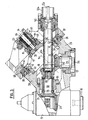
- FIG. 3 shows the essential details of the structure, insofar as they are important for the invention. Corresponding parts are identified in the same way as in FIGS. 1 and 2.
- FIG. 3 shows the bevel gear 22, which is connected to the spindle in a rotationally fixed manner and is in engagement with the bevel gear 21.
- the intermediate shaft 20 and the auxiliary shaft 24 are mounted by means of roller bearings 25 in bearing heads 26 and 27, which are screwed to the uniform body 28 of the spindle head 13. As mentioned, the shafts 20 and 24 are thus mounted in a rigid mutual position.
- the two bevel gears 18 and 19, of which the bevel gear 18 is firmly wedged to the shaft 20, have axially grooved recesses 29 on their free end faces.
- the corresponding axially grooved, hollow part 12a of the drive shaft engages in the working position of the spindle head shown in FIG. 3 as a coupling part in the grooved recess of the bevel gear 18 and is thus rotatably coupled to this bevel gear.
- the body 28 of the spindle head 13 is rigidly connected to a dome-shaped carrier 30, which in turn is firmly screwed to a bush 31.
- the outer, upper end of the sleeve 31 is designed as a toothed ring 32, in which a toothed rack 33 engages, which can be displaced by means of a cylinder, not shown, in order to move over the toothed ring 32, the sleeve 31 and thus the carrier 30 and the spindle head 13 in the way described above by 180 ° each to swivel one into the other working position.
- a spring 34 which is supported on the inner end of a bush 35, pulls the carrier 30 and thus the body 28 of the spindle head upward via a bolt 36 and presses the coupling and orientation teeth of a ring gear 38 connected to the body 28 into the counter teeth of a Sprocket 39 on the spindle head carrier 9.
- This pressure is supported during normal operation by introducing pressure medium through channels 40 into an annular space 41, in which the pressure medium presses against the surface 42 of the carrier 30.
- An annular space 43 is also formed between the sleeves 31 and 35, in which pressure medium can be introduced through a bore 44 in order to move the sleeve 31 with the carrier 30 and the spindle head 13 downward against the action of the spring 34 when the annular space 41 is depressurized and thus disengage the ring gear 38 from the ring gear 39 and allow the spindle head 13 to pivot.
- the end of the shaft part 12a on the right in FIG. 3 is displaceably guided there in a bush 45, which in turn is rotatably mounted in the spindle head carrier.
- the bushing 45 is screwed to the hollow shaft section 12b, which in turn is connected to the hollow shaft part 12c.
- the piston rod 12e and the shaft part 12a connected to it are axially displaceable, the shaft part 12a with its grooved outer side always remaining non-rotatably connected to the correspondingly grooved end 45a of the bush 45.
- the stroke of the piston 12d or the piston rod 12e is dimensioned such that when the piston 12d moves from the left to the right cylinder end, the shaft part 12a is displaced to such an extent that it is completely disengaged from the area of the rotating parts of the spindle head.
- it is from an opening 46 of the carrier 30 completely disengaged, so that the spindle head can now be freely pivoted through 180 °.
- a second opening 47 reaches the position previously assumed by the opening 46, through which the shaft part 12a can then be inserted again to the left and can be coupled with the bevel gear 19, which is now coaxial with the drive shaft.
- the end positions of the shaft part 12a can be locked here.
- the shaft part 12a is coupled to the bevel gear 18 and can drive the spindle 16. Overpressure prevails in the annular chamber 41, which presses the carrier 30 upward and thus presses the ring gear 38 into the ring gear 39, which results in a very precise and stable position determination of the spindle head. If the spindle head is to be transferred into the working position according to FIG. 2, the shaft part 12a is shifted to the right when the machine is stationary and disengaged from the bevel gear 18 and from the carrier 30. Then the pressure in the annular chamber 41 is released and overpressure is generated in the annular chamber 43.
- the carrier 30 with the spindle head is thus displaced downward to the left and the ring gear 38 is disengaged from the ring gear 39.
- the spindle head is now pivoted through 180 ° via the toothed rack 33.
- the pressure in the annular chamber 43 is released, whereby the spring 34 lifts the spindle head 13 via the bolt 36 and the carrier 30 and the ring gears 38 and 39 are softly engaged.
- the annular chamber 41 is then pressurized again and finally the shaft part 12a is displaced to the left through the opening 47 and coupled to the bevel gear 19.
- the machine is thus ready to carry out machining with the spindle 16 now lying horizontally.
- This shaft part is therefore relatively long and to disengage and in order to move a correspondingly long distance, because it must be disengaged completely from the parts of the spindle head to be pivoted, in particular from the dome-shaped carrier 30. Since the mechanisms for the pivoting movement and are arranged to lock the spindle head in the spindle head carrier, there is a free space in the center for the bevel gears 18 and 19, the dome-shaped carrier 30 and the shaft part 12a. This design favors the compact construction of the spindle head already mentioned.
- the drive unit can be arranged in the immediate vicinity of the attachment point of the spindle head carrier on the machine frame.
- the decisive factor is the requirement that two mirror-inverted couplings are arranged, which are permanently in rotary connection with the spindle, and which can optionally be coupled to the drive shaft.
- the spindle 16 could be driven by the shaft 24 or by the bevel gear 19 via a spur gear.
- the respective end positions at the Axial displacement of the shaft part 12a or the spindle head and when pivoting the spindle head can be determined by contactless sensors and thus the drive means for these movements can be controlled.
Landscapes
- Engineering & Computer Science (AREA)
- Mechanical Engineering (AREA)
- Machine Tool Units (AREA)
- Jigs For Machine Tools (AREA)
Priority Applications (2)
| Application Number | Priority Date | Filing Date | Title |
|---|---|---|---|
| EP19870810258 EP0287748B1 (fr) | 1987-04-23 | 1987-04-23 | Machine-outil |
| DE8787810258T DE3780159D1 (de) | 1987-04-23 | 1987-04-23 | Werkzeugmaschine. |
Applications Claiming Priority (1)
| Application Number | Priority Date | Filing Date | Title |
|---|---|---|---|
| EP19870810258 EP0287748B1 (fr) | 1987-04-23 | 1987-04-23 | Machine-outil |
Publications (2)
| Publication Number | Publication Date |
|---|---|
| EP0287748A1 true EP0287748A1 (fr) | 1988-10-26 |
| EP0287748B1 EP0287748B1 (fr) | 1992-07-01 |
Family
ID=8198401
Family Applications (1)
| Application Number | Title | Priority Date | Filing Date |
|---|---|---|---|
| EP19870810258 Expired - Lifetime EP0287748B1 (fr) | 1987-04-23 | 1987-04-23 | Machine-outil |
Country Status (2)
| Country | Link |
|---|---|
| EP (1) | EP0287748B1 (fr) |
| DE (1) | DE3780159D1 (fr) |
Cited By (4)
| Publication number | Priority date | Publication date | Assignee | Title |
|---|---|---|---|---|
| EP0408264A1 (fr) * | 1989-07-11 | 1991-01-16 | Tai-Her Yang | Modification constructive de l'arbre principal de machines-outils |
| EP0664176A1 (fr) * | 1994-01-25 | 1995-07-26 | DECKEL MAHO GmbH | Fraiseuse-aléseuse universelle |
| DE102006026193B3 (de) * | 2006-06-06 | 2008-01-31 | Grotefeld Gmbh | Winkelaggregat |
| CN105127771A (zh) * | 2015-10-08 | 2015-12-09 | 湘潭大学 | 一种五轴数控机床的旋转坐标轴c'—a'转换装置 |
Families Citing this family (1)
| Publication number | Priority date | Publication date | Assignee | Title |
|---|---|---|---|---|
| EP4029637A1 (fr) * | 2020-08-31 | 2022-07-20 | SHW Werkzeugmaschinen GmbH | Tête de fraisage à haute précision, fraiseuse dotée d'une tête de fraisage et procédé de positionnement d'une tête de fraisage à haute précision |
Citations (3)
| Publication number | Priority date | Publication date | Assignee | Title |
|---|---|---|---|---|
| DE303777C (fr) * | ||||
| EP0087672A1 (fr) * | 1982-02-19 | 1983-09-07 | Friedrich Deckel Aktiengesellschaft | Machine-outil avec tête de broche orientable |
| FR2526343A1 (fr) * | 1982-05-06 | 1983-11-10 | Index Werke Kg Hahn & Tessky | Tour automatique revolver multibroche |
-
1987
- 1987-04-23 EP EP19870810258 patent/EP0287748B1/fr not_active Expired - Lifetime
- 1987-04-23 DE DE8787810258T patent/DE3780159D1/de not_active Expired - Fee Related
Patent Citations (3)
| Publication number | Priority date | Publication date | Assignee | Title |
|---|---|---|---|---|
| DE303777C (fr) * | ||||
| EP0087672A1 (fr) * | 1982-02-19 | 1983-09-07 | Friedrich Deckel Aktiengesellschaft | Machine-outil avec tête de broche orientable |
| FR2526343A1 (fr) * | 1982-05-06 | 1983-11-10 | Index Werke Kg Hahn & Tessky | Tour automatique revolver multibroche |
Cited By (5)
| Publication number | Priority date | Publication date | Assignee | Title |
|---|---|---|---|---|
| EP0408264A1 (fr) * | 1989-07-11 | 1991-01-16 | Tai-Her Yang | Modification constructive de l'arbre principal de machines-outils |
| EP0664176A1 (fr) * | 1994-01-25 | 1995-07-26 | DECKEL MAHO GmbH | Fraiseuse-aléseuse universelle |
| US5533846A (en) * | 1994-01-25 | 1996-07-09 | Deckel Maho Gmbh | Universal milling and drilling machine |
| DE102006026193B3 (de) * | 2006-06-06 | 2008-01-31 | Grotefeld Gmbh | Winkelaggregat |
| CN105127771A (zh) * | 2015-10-08 | 2015-12-09 | 湘潭大学 | 一种五轴数控机床的旋转坐标轴c'—a'转换装置 |
Also Published As
| Publication number | Publication date |
|---|---|
| DE3780159D1 (de) | 1992-08-06 |
| EP0287748B1 (fr) | 1992-07-01 |
Similar Documents
| Publication | Publication Date | Title |
|---|---|---|
| DE2944983C2 (de) | Spindelstock für eine Universal-Fräs- und Bohrmaschine | |
| DE3316867C2 (fr) | ||
| DE69107639T2 (de) | Antriebsvorrichtung für Werkzeuge und Revolverkopf. | |
| EP3939751A1 (fr) | Articulation de bras pour un manipulateur et manipulateur | |
| DE4341167A1 (de) | Einrichtung zur Übertragung eines Druckmediums | |
| EP0120302B1 (fr) | Tête de fraisage universelle pour machine-outil | |
| DE9202252U1 (de) | Werkzeugrevolver | |
| WO1989006176A1 (fr) | Tour | |
| EP0396876A1 (fr) | Poinçonneuse à révolver avec outil rotatif | |
| EP0287748A1 (fr) | Machine-outil | |
| DE1098325B (de) | Mehrspindeldrehautomat | |
| DE1935019C3 (de) | Vorrichtung zum Festklemmen der Werkzeugspindel einer Werkzeugmaschine | |
| EP0676278B1 (fr) | Dispositif de réglage de la course pour presses ou poinçonneuses | |
| EP0545006B1 (fr) | Porte-outil revolver | |
| DE2047311C3 (de) | Spindellagerung | |
| DE4308419A1 (de) | Werkzeugrevolver | |
| DE3844343C2 (de) | Kraftbetätigtes Backenspannfutter für exzentrisch zu spannende Werkstücke, insbesondere Kurbelwellen | |
| EP0539667B1 (fr) | Tourelle porte-outil | |
| DE7618904U1 (de) | Spanneinrichtung an einer werkzeugmaschine | |
| EP0242521B1 (fr) | Transmission pour une bride de sortie notamment appropriée à recevoir l'outil de préhension d'un robot | |
| DE3530860A1 (de) | Mehrspindeldrehautomat | |
| DE19621356C2 (de) | Vorrichtung für einen Werkzeugsternrevolver | |
| DE4402949C2 (de) | Werkzeugmaschine mit auswechselbaren Bearbeitungsköpfen | |
| DE3405704C2 (fr) | ||
| DE3446826A1 (de) | Backenspannfutter fuer drehmaschinen zur bearbeitung von werkstuecken unter mehreren bearbeitungsachsen |
Legal Events
| Date | Code | Title | Description |
|---|---|---|---|
| PUAI | Public reference made under article 153(3) epc to a published international application that has entered the european phase |
Free format text: ORIGINAL CODE: 0009012 |
|
| AK | Designated contracting states |
Kind code of ref document: A1 Designated state(s): AT BE CH DE ES FR GB GR IT LI LU NL SE |
|
| RBV | Designated contracting states (corrected) |
Designated state(s): CH DE FR IT LI |
|
| 17P | Request for examination filed |
Effective date: 19890403 |
|
| 17Q | First examination report despatched |
Effective date: 19900424 |
|
| GRAA | (expected) grant |
Free format text: ORIGINAL CODE: 0009210 |
|
| AK | Designated contracting states |
Kind code of ref document: B1 Designated state(s): CH DE FR IT LI |
|
| REF | Corresponds to: |
Ref document number: 3780159 Country of ref document: DE Date of ref document: 19920806 |
|
| ITF | It: translation for a ep patent filed | ||
| ET | Fr: translation filed | ||
| PGFP | Annual fee paid to national office [announced via postgrant information from national office to epo] |
Ref country code: CH Payment date: 19930423 Year of fee payment: 7 |
|
| PLBE | No opposition filed within time limit |
Free format text: ORIGINAL CODE: 0009261 |
|
| STAA | Information on the status of an ep patent application or granted ep patent |
Free format text: STATUS: NO OPPOSITION FILED WITHIN TIME LIMIT |
|
| 26N | No opposition filed | ||
| PGFP | Annual fee paid to national office [announced via postgrant information from national office to epo] |
Ref country code: DE Payment date: 19930630 Year of fee payment: 7 |
|
| PGFP | Annual fee paid to national office [announced via postgrant information from national office to epo] |
Ref country code: FR Payment date: 19940322 Year of fee payment: 8 |
|
| PG25 | Lapsed in a contracting state [announced via postgrant information from national office to epo] |
Ref country code: LI Effective date: 19940430 Ref country code: CH Effective date: 19940430 |
|
| PG25 | Lapsed in a contracting state [announced via postgrant information from national office to epo] |
Ref country code: FR Effective date: 19941229 |
|
| REG | Reference to a national code |
Ref country code: CH Ref legal event code: PL |
|
| PG25 | Lapsed in a contracting state [announced via postgrant information from national office to epo] |
Ref country code: DE Effective date: 19950103 |
|
| REG | Reference to a national code |
Ref country code: FR Ref legal event code: ST |
|
| PG25 | Lapsed in a contracting state [announced via postgrant information from national office to epo] |
Ref country code: IT Free format text: LAPSE BECAUSE OF NON-PAYMENT OF DUE FEES;WARNING: LAPSES OF ITALIAN PATENTS WITH EFFECTIVE DATE BEFORE 2007 MAY HAVE OCCURRED AT ANY TIME BEFORE 2007. THE CORRECT EFFECTIVE DATE MAY BE DIFFERENT FROM THE ONE RECORDED. Effective date: 20050423 |