EP0287779A1 - Chauffe-eau solaire - Google Patents
Chauffe-eau solaire Download PDFInfo
- Publication number
- EP0287779A1 EP0287779A1 EP88102904A EP88102904A EP0287779A1 EP 0287779 A1 EP0287779 A1 EP 0287779A1 EP 88102904 A EP88102904 A EP 88102904A EP 88102904 A EP88102904 A EP 88102904A EP 0287779 A1 EP0287779 A1 EP 0287779A1
- Authority
- EP
- European Patent Office
- Prior art keywords
- water heater
- absorber
- heater according
- water
- phase change
- Prior art date
- Legal status (The legal status is an assumption and is not a legal conclusion. Google has not performed a legal analysis and makes no representation as to the accuracy of the status listed.)
- Withdrawn
Links
Images

Classifications
-
- F—MECHANICAL ENGINEERING; LIGHTING; HEATING; WEAPONS; BLASTING
- F24—HEATING; RANGES; VENTILATING
- F24S—SOLAR HEAT COLLECTORS; SOLAR HEAT SYSTEMS
- F24S80/00—Details, accessories or component parts of solar heat collectors not provided for in groups F24S10/00-F24S70/00
- F24S80/50—Elements for transmitting incoming solar rays and preventing outgoing heat radiation; Transparent coverings
- F24S80/52—Elements for transmitting incoming solar rays and preventing outgoing heat radiation; Transparent coverings characterised by the material
-
- F—MECHANICAL ENGINEERING; LIGHTING; HEATING; WEAPONS; BLASTING
- F24—HEATING; RANGES; VENTILATING
- F24S—SOLAR HEAT COLLECTORS; SOLAR HEAT SYSTEMS
- F24S10/00—Solar heat collectors using working fluids
- F24S10/50—Solar heat collectors using working fluids the working fluids being conveyed between plates
- F24S10/502—Solar heat collectors using working fluids the working fluids being conveyed between plates having conduits formed by paired plates and internal partition means
-
- F—MECHANICAL ENGINEERING; LIGHTING; HEATING; WEAPONS; BLASTING
- F24—HEATING; RANGES; VENTILATING
- F24S—SOLAR HEAT COLLECTORS; SOLAR HEAT SYSTEMS
- F24S50/00—Arrangements for controlling solar heat collectors
- F24S50/80—Arrangements for controlling solar heat collectors for controlling collection or absorption of solar radiation
-
- F—MECHANICAL ENGINEERING; LIGHTING; HEATING; WEAPONS; BLASTING
- F24—HEATING; RANGES; VENTILATING
- F24S—SOLAR HEAT COLLECTORS; SOLAR HEAT SYSTEMS
- F24S60/00—Arrangements for storing heat collected by solar heat collectors
- F24S60/10—Arrangements for storing heat collected by solar heat collectors using latent heat
-
- F—MECHANICAL ENGINEERING; LIGHTING; HEATING; WEAPONS; BLASTING
- F24—HEATING; RANGES; VENTILATING
- F24S—SOLAR HEAT COLLECTORS; SOLAR HEAT SYSTEMS
- F24S60/00—Arrangements for storing heat collected by solar heat collectors
- F24S60/30—Arrangements for storing heat collected by solar heat collectors storing heat in liquids
-
- F—MECHANICAL ENGINEERING; LIGHTING; HEATING; WEAPONS; BLASTING
- F24—HEATING; RANGES; VENTILATING
- F24S—SOLAR HEAT COLLECTORS; SOLAR HEAT SYSTEMS
- F24S80/00—Details, accessories or component parts of solar heat collectors not provided for in groups F24S10/00-F24S70/00
- F24S80/50—Elements for transmitting incoming solar rays and preventing outgoing heat radiation; Transparent coverings
- F24S80/56—Elements for transmitting incoming solar rays and preventing outgoing heat radiation; Transparent coverings characterised by means for preventing heat loss
-
- Y—GENERAL TAGGING OF NEW TECHNOLOGICAL DEVELOPMENTS; GENERAL TAGGING OF CROSS-SECTIONAL TECHNOLOGIES SPANNING OVER SEVERAL SECTIONS OF THE IPC; TECHNICAL SUBJECTS COVERED BY FORMER USPC CROSS-REFERENCE ART COLLECTIONS [XRACs] AND DIGESTS
- Y02—TECHNOLOGIES OR APPLICATIONS FOR MITIGATION OR ADAPTATION AGAINST CLIMATE CHANGE
- Y02E—REDUCTION OF GREENHOUSE GAS [GHG] EMISSIONS, RELATED TO ENERGY GENERATION, TRANSMISSION OR DISTRIBUTION
- Y02E10/00—Energy generation through renewable energy sources
- Y02E10/40—Solar thermal energy, e.g. solar towers
- Y02E10/44—Heat exchange systems
Definitions
- the invention relates to the hot water preparation by a solar collector, which is filled with a phase change material - phase change material - which stores latent heat by changing its phase, preferably between solid and liquid. It is known to use such collectors in a two-circuit system in which the radiation energy, which fluctuates in intensity, is stored as heat via the solar collector and is given to a flow or heat transport medium in a circuit which is passed via a heat exchanger with a line system for the one to be heated Water is coupled; see. For example, DE-OS 33 02 324.
- the invention is based, to simplify the known water heaters of this type plant and installation technology significantly the task. This object is achieved according to the invention in a water heater according to the preamble of patent claim 1 by combining all the features according to this patent claim.
- the combination of collector and storage in one structural unit enables considerable savings in pipes and circulants. It also allows a modular system design, which allows systems with water heaters according to the invention to be installed retrospectively in existing water heating systems while adapting to individual needs. If the solar radiation output is insufficient, the solar collector according to the invention can be used for preheating with subsequent conventional post-heating, for example in existing hot water heating systems.
- the time-variable radiation supply can be used in such a way that a temporary excess is used to melt the phase change material and thus an energy reserve is stored for periods without irradiation, which is suitable when the radiation is suitable
- climate marginal conditions enable constant use as a continuous-flow heater with a constant removal temperature.
- the removal temperature can be varied by choosing a phase change material with a corresponding transition temperature.
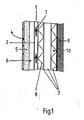
- a solar collector designed according to the invention as a water heater with an absorber through which the water 1 to be heated flows, as indicated by the flow arrows.
- the collector cover consisting of the glass cover 4 as transparent weather protection, the heat insulation layer 5 and the air gap 6, which is as permeable as possible for the solar radiation and which allows only minimal heat emission to the external environment.
- the water 1 is thus heated essentially directly by the solar radiation without the interposition of a storage medium.
- the other absorber surfaces, in particular the rear side 7, are connected in very good heat-conducting contact with an encapsulated package made of metal ribs 8.
- the narrow rib spaces 10 are filled with the phase change material as storage medium 3.
- the rib package consists of corrugated sheets or sheet metal ribs which are as low in mass as possible and which can be manufactured industrially and which are interconnected in layers.
- the rib density is determined according to the maximum irradiation power dimensioned; the depth of the entire set of fins (between the back of the absorber 7 and the rear thermal insulation 9 of the collector) results from the climate-appropriate dimensioning of the set of fins and the desired storage capacity.
- the solar energy converted into heat in the absorber which is not dissipated by the hot water 1, is fed to the storage consisting of the fins 8 and the storage medium 3 for later use.
- the water 1 flowing through the absorber is thus largely kept at a constant temperature, overheating with problematic vapor formation is avoided with regular heat removal.
- FIG. 2 shows a partially cut collector storage module as an example of the practical design of a water heater according to the invention.
- modules can be connected in series and / or in parallel to modular systems or inserted into the water supply of an existing water heating system via the water inlet and outlet sockets Z and A.
- the supplied water to be heated 1 emerges from the rear 7 of the absorber. Between the surface 2 and the back 7 of the absorber there are webs which cause a meandering water flow from Z to A.
- the water 1 is heated by the solar energy absorbed by the surface 2.
- the rib packet formed from the sheet metal ribs 8 is connected to the absorber rear side 7 in very good heat-conducting contact, the narrow rib spaces 10 of which are filled with the phase change material as a storage medium.
- the water flow is adapted to the melting and solidification behavior of the phase change material such that the change in volume associated with the phase change does not lead to destructive stresses in the fin package 8.
- Modules according to FIG. 2 are advantageously used individually or in a modular network in the facades of buildings exposed to solar radiation.
- the storage medium can also be other phase material that is known from the relevant literature. Zeolites can also be used. A simple system would also be to simply use water.
- the transparent thermal insulation layer 5 should on the one hand let as much light through as possible in order to heat the absorber 2, 7, on the other hand it should be heat-insulating so as not to cool the accumulator or the phase material 3 when it is cloudy or at night.
- the thermal barrier coating can be, for example, polymethyl methacrylate according to DE C1 31 24 980, a transparent foam that can also have a capillary structure. Furthermore, it can consist of silica gel, as is known from EU A1 84 102 626.3 or from the Lawrence Berkeley laboratory report Transparent Silica Airgel ... by Michael Rubin and Carl M. Lampert, June 82.
- the insulation layer can consist of a honeycomb structure made of plastic lamellae, the honeycomb diameter being smaller than the layer thickness or honeycomb length, the dimensions could be that of a honeycomb, and capillary structures can also be used.
- the air gap 6 serves to ensure that, in the event that the thermal insulation layer is sensitive to heat, there is no direct contact of the thermal insulation layer with the absorber, since the absorber can reach temperatures of greater than 400 K when it is at a standstill, that is to say without taking water and when the phase material is heated.
- the dimensions in FIG. 1 are only schematic, the thermal barrier coating can be about 1-3 cm thick, the air gap 1-3 cm, the layer thickness of the phase material 3-20 cm or even thicker.
Landscapes
- Engineering & Computer Science (AREA)
- Physics & Mathematics (AREA)
- Life Sciences & Earth Sciences (AREA)
- Sustainable Development (AREA)
- Sustainable Energy (AREA)
- Thermal Sciences (AREA)
- Chemical & Material Sciences (AREA)
- Combustion & Propulsion (AREA)
- Mechanical Engineering (AREA)
- General Engineering & Computer Science (AREA)
- Heat-Pump Type And Storage Water Heaters (AREA)
Applications Claiming Priority (2)
| Application Number | Priority Date | Filing Date | Title |
|---|---|---|---|
| DE19873706196 DE3706196A1 (de) | 1987-02-26 | 1987-02-26 | Warmwasserbereiter in form eines solarkollektors |
| DE3706196U | 1987-02-26 |
Publications (1)
| Publication Number | Publication Date |
|---|---|
| EP0287779A1 true EP0287779A1 (fr) | 1988-10-26 |
Family
ID=6321819
Family Applications (1)
| Application Number | Title | Priority Date | Filing Date |
|---|---|---|---|
| EP88102904A Withdrawn EP0287779A1 (fr) | 1987-02-26 | 1988-02-26 | Chauffe-eau solaire |
Country Status (2)
| Country | Link |
|---|---|
| EP (1) | EP0287779A1 (fr) |
| DE (1) | DE3706196A1 (fr) |
Cited By (4)
| Publication number | Priority date | Publication date | Assignee | Title |
|---|---|---|---|---|
| EP0770835A3 (fr) * | 1995-10-26 | 1998-07-29 | Ernst Dipl.-Ing. Reichert | Collecteur solaire pour le chauffage d'eau |
| EP2522927A3 (fr) * | 2011-05-13 | 2013-01-23 | Termo Fluids, S.L. | Collecteur solaire thermique avec isolation transparente |
| WO2013128058A1 (fr) * | 2012-03-02 | 2013-09-06 | Universitat Politècnica De Catalunya | Capteur solaire pourvu d'une isolation transparente en plastique et protection contre une surchauffe |
| ES2550397A1 (es) * | 2014-05-06 | 2015-11-06 | Valoralia I Mad D, S.L. | Colector solar mixto con acumulación |
Families Citing this family (9)
| Publication number | Priority date | Publication date | Assignee | Title |
|---|---|---|---|---|
| DE4325887C2 (de) * | 1993-08-02 | 1997-04-03 | Innotech Ingenieursgesellschaf | Kollektor zur solarthermischen Erwärmung eines flüssigen Wärmetauschermediums |
| AUPM835894A0 (en) * | 1994-09-22 | 1994-10-13 | Thermal Energy Accumulator Products Pty Ltd | A temperature control system for liquids |
| DE19629670A1 (de) * | 1996-07-23 | 1998-01-29 | Friedolf Mutschler | Verfahren und Vorrichtung zur Lenkung des Sonnenlichtes und Temperaturregelung |
| DE10034683C1 (de) * | 2000-05-31 | 2002-01-03 | Ulrich Schaberg | Kompakte Solaranlage zur Brauchwassererwärmung |
| NO313473B1 (no) * | 2001-10-12 | 2002-10-07 | Solarnor As | Solfangerplate, fremgangsmåte for driftssikring av en solfanger og fremgangsmåte for fremstilling av en solfangerplate |
| RU2230263C2 (ru) * | 2002-06-28 | 2004-06-10 | Дагестанский государственный университет | Солнечный коллектор |
| UA65474C2 (en) * | 2003-08-05 | 2006-09-15 | Vitalii Vasyliovych Strashko | Solar collector |
| DE102004053802A1 (de) * | 2004-11-08 | 2006-05-11 | Fraunhofer-Gesellschaft zur Förderung der angewandten Forschung e.V. | Solarenergiemodul |
| DE102008053192A1 (de) | 2008-10-24 | 2010-04-29 | Fraunhofer-Gesellschaft zur Förderung der angewandten Forschung e.V. | Solarkollektor mit Kühlfunktion |
Citations (7)
| Publication number | Priority date | Publication date | Assignee | Title |
|---|---|---|---|---|
| US2595905A (en) * | 1946-08-29 | 1952-05-06 | Telkes Maria | Radiant energy heat transfer device |
| DE2330780A1 (de) * | 1973-06-16 | 1975-01-16 | Nikolaus Laing | Verfahren zur versorgung von waermegleichrichter-dachplatten oder waermerohren mit waermetraegern unterschiedlicher siedetemperatur |
| DE2745324A1 (de) * | 1977-10-06 | 1979-04-12 | Stichting Bouwcentrum | Verfahren und vorrichtung zur ausnutzung von sonnenwaerme |
| FR2433716A1 (fr) * | 1978-08-17 | 1980-03-14 | Euratom | Systeme integre de reception et d'emmagasinage de l'energie solaire |
| DE3302324A1 (de) * | 1983-01-25 | 1984-08-02 | Fraunhofer-Gesellschaft zur Förderung der angewandten Forschung e.V., 8000 München | Waermespeicheranordnung fuer gebaeude, insbesondere zur speicherung von solarenergie |
| EP0121800A1 (fr) * | 1983-03-14 | 1984-10-17 | Volksbank Remscheid eG | Collecteur solaire à couche fixé du côté extérieur |
| WO1985000212A1 (fr) * | 1983-06-27 | 1985-01-17 | Charles Stein | Systeme de chauffage solaire d'air |
Family Cites Families (1)
| Publication number | Priority date | Publication date | Assignee | Title |
|---|---|---|---|---|
| DE3120173A1 (de) * | 1981-05-21 | 1982-12-09 | Hoechst Ag | Flaechenhaftes flexibles waermeaustauscherelement |
-
1987
- 1987-02-26 DE DE19873706196 patent/DE3706196A1/de not_active Ceased
-
1988
- 1988-02-26 EP EP88102904A patent/EP0287779A1/fr not_active Withdrawn
Patent Citations (7)
| Publication number | Priority date | Publication date | Assignee | Title |
|---|---|---|---|---|
| US2595905A (en) * | 1946-08-29 | 1952-05-06 | Telkes Maria | Radiant energy heat transfer device |
| DE2330780A1 (de) * | 1973-06-16 | 1975-01-16 | Nikolaus Laing | Verfahren zur versorgung von waermegleichrichter-dachplatten oder waermerohren mit waermetraegern unterschiedlicher siedetemperatur |
| DE2745324A1 (de) * | 1977-10-06 | 1979-04-12 | Stichting Bouwcentrum | Verfahren und vorrichtung zur ausnutzung von sonnenwaerme |
| FR2433716A1 (fr) * | 1978-08-17 | 1980-03-14 | Euratom | Systeme integre de reception et d'emmagasinage de l'energie solaire |
| DE3302324A1 (de) * | 1983-01-25 | 1984-08-02 | Fraunhofer-Gesellschaft zur Förderung der angewandten Forschung e.V., 8000 München | Waermespeicheranordnung fuer gebaeude, insbesondere zur speicherung von solarenergie |
| EP0121800A1 (fr) * | 1983-03-14 | 1984-10-17 | Volksbank Remscheid eG | Collecteur solaire à couche fixé du côté extérieur |
| WO1985000212A1 (fr) * | 1983-06-27 | 1985-01-17 | Charles Stein | Systeme de chauffage solaire d'air |
Cited By (5)
| Publication number | Priority date | Publication date | Assignee | Title |
|---|---|---|---|---|
| EP0770835A3 (fr) * | 1995-10-26 | 1998-07-29 | Ernst Dipl.-Ing. Reichert | Collecteur solaire pour le chauffage d'eau |
| EP2522927A3 (fr) * | 2011-05-13 | 2013-01-23 | Termo Fluids, S.L. | Collecteur solaire thermique avec isolation transparente |
| WO2013128058A1 (fr) * | 2012-03-02 | 2013-09-06 | Universitat Politècnica De Catalunya | Capteur solaire pourvu d'une isolation transparente en plastique et protection contre une surchauffe |
| ES2424830A1 (es) * | 2012-03-02 | 2013-10-08 | Universitat Politècnica De Catalunya | Captador solar con aislamiento transparente plástico y protección al sobrecalentamiento |
| ES2550397A1 (es) * | 2014-05-06 | 2015-11-06 | Valoralia I Mad D, S.L. | Colector solar mixto con acumulación |
Also Published As
| Publication number | Publication date |
|---|---|
| DE3706196A1 (de) | 1988-09-29 |
Similar Documents
| Publication | Publication Date | Title |
|---|---|---|
| EP0287779A1 (fr) | Chauffe-eau solaire | |
| DE2231972C2 (de) | Anordnung zum Lüften eines Aufenthaltsraumes | |
| EP0016337B1 (fr) | Dispositif et procédé de climatisation d'un bâtiment | |
| EP2694885B1 (fr) | Dispositif et procédé de conversion d'énergie solaire rayonnante en courant électrique et/ou chaleur | |
| DE2602530B1 (de) | Latentwaermespeicher | |
| DE102008009553A9 (de) | Integrierte außenliegende Wandheizung-ein Verfahren zur Nutzung der massiven Außenwand als ein in ein Gebäudeheiz- und Kühlsystem integrierter thermischer Speicher und als Murokausten- Wärmeübertrager | |
| DE3003962C2 (de) | Sonnenenergieanlage mit Wärmespeicher | |
| DE2806337A1 (de) | Sonnenkollektor zur unmittelbaren umwandlung der zugefuehrten waermeenergie in elektrische energie | |
| DE3419797A1 (de) | Solar-energiewandler | |
| EP0121800A1 (fr) | Collecteur solaire à couche fixé du côté extérieur | |
| CH703472A1 (de) | Sonnenhybridkollektor. | |
| EP0048385A2 (fr) | Procédé pour le chauffage de bâtiments par un procédé pompe à chaleur | |
| SE434186B (sv) | Solmodul | |
| EP1073868A1 (fr) | Cellule solaire comportant un collecteur solaire et des elements accumulateurs | |
| DE10023833C1 (de) | Solarflachkollektor zur Erhitzung von gasförmigen Fluiden | |
| DE3102869A1 (de) | Vorrichtung zur speicherung von waerme fuer heizungsanlagen | |
| DE10034683C1 (de) | Kompakte Solaranlage zur Brauchwassererwärmung | |
| DE2900875C2 (de) | Solarkollektor | |
| EP0796520A1 (fr) | Generateur solaire | |
| DE3629816C2 (fr) | ||
| DE102016001350B4 (de) | Verfahren und Vorrichtung zur Bereitstellung von Raumwärme und Warmwasser durch Nutzung solarer Strahlungsenergie | |
| CH654650A5 (en) | Solar collector for heating a heat-transfer medium | |
| WO1987000607A1 (fr) | Chauffage solaire pour batiments | |
| DE2745324A1 (de) | Verfahren und vorrichtung zur ausnutzung von sonnenwaerme | |
| DE2649807A1 (de) | Sonnenkollektor |
Legal Events
| Date | Code | Title | Description |
|---|---|---|---|
| PUAI | Public reference made under article 153(3) epc to a published international application that has entered the european phase |
Free format text: ORIGINAL CODE: 0009012 |
|
| 17P | Request for examination filed |
Effective date: 19880719 |
|
| AK | Designated contracting states |
Kind code of ref document: A1 Designated state(s): AT CH DE ES FR GB GR IT LI NL SE |
|
| 17Q | First examination report despatched |
Effective date: 19900327 |
|
| STAA | Information on the status of an ep patent application or granted ep patent |
Free format text: STATUS: THE APPLICATION IS DEEMED TO BE WITHDRAWN |
|
| 18D | Application deemed to be withdrawn |
Effective date: 19901106 |