EP0287801A2 - Hydraulic turbine system - Google Patents
Hydraulic turbine system Download PDFInfo
- Publication number
- EP0287801A2 EP0287801A2 EP88103961A EP88103961A EP0287801A2 EP 0287801 A2 EP0287801 A2 EP 0287801A2 EP 88103961 A EP88103961 A EP 88103961A EP 88103961 A EP88103961 A EP 88103961A EP 0287801 A2 EP0287801 A2 EP 0287801A2
- Authority
- EP
- European Patent Office
- Prior art keywords
- turbines
- turbine
- channel
- driving system
- pressurized oil
- Prior art date
- Legal status (The legal status is an assumption and is not a legal conclusion. Google has not performed a legal analysis and makes no representation as to the accuracy of the status listed.)
- Withdrawn
Links
Images


Classifications
-
- F—MECHANICAL ENGINEERING; LIGHTING; HEATING; WEAPONS; BLASTING
- F16—ENGINEERING ELEMENTS AND UNITS; GENERAL MEASURES FOR PRODUCING AND MAINTAINING EFFECTIVE FUNCTIONING OF MACHINES OR INSTALLATIONS; THERMAL INSULATION IN GENERAL
- F16H—GEARING
- F16H48/00—Differential gearings
- F16H48/12—Differential gearings without gears having orbital motion
- F16H48/18—Differential gearings without gears having orbital motion with fluid gearing
-
- B—PERFORMING OPERATIONS; TRANSPORTING
- B60—VEHICLES IN GENERAL
- B60K—ARRANGEMENT OR MOUNTING OF PROPULSION UNITS OR OF TRANSMISSIONS IN VEHICLES; ARRANGEMENT OR MOUNTING OF PLURAL DIVERSE PRIME-MOVERS IN VEHICLES; AUXILIARY DRIVES FOR VEHICLES; INSTRUMENTATION OR DASHBOARDS FOR VEHICLES; ARRANGEMENTS IN CONNECTION WITH COOLING, AIR INTAKE, GAS EXHAUST OR FUEL SUPPLY OF PROPULSION UNITS IN VEHICLES
- B60K17/00—Arrangement or mounting of transmissions in vehicles
- B60K17/04—Arrangement or mounting of transmissions in vehicles characterised by arrangement, location or kind of gearing
- B60K17/10—Arrangement or mounting of transmissions in vehicles characterised by arrangement, location or kind of gearing of fluid gearing
Definitions
- the power is transferred from the engine's rotating flywheel to the drive wheels through the clutch (in standards) or torque converter (in automatics) to the transmission drive shaft, differential and then to the wheels.
- gears are often noisy and jerky.
- the clutch In the standard transmission, the clutch is responsible for permitting gradual application of the engine power to move the car; it enables the driver to disengage the engine from the drive-line so that the gears may be manually shifted from one gear to another.
- the gears In the automatic transmission the gears are changed with the use of the torque converter usually causing a jerking sensation with a hesitation before it actually changes.
- the planetary gear housing 1 houses the planetary gears.
- the axle 3 goes to the wheels and is splined into the internal ring gear 4.
- the planetary gear shaft 7 is threaded into the turbine housing 14.
- the axle 3 is fitted into a bearing, bushing or spacer 13 which is fitted in the gear housing 1.
- the turbine housing 14 houses the two indepedent turbines.
- the planetary gear housing 1 houses the planetary gears 6 consisting of the internal ring gear 4 and the sun gear 8.
- the diagram shows the top plate of the planet carrier 5, the planetary gear shafts 7, and the turbine shaft 9.
- the base plate of the planetary gear housing is also the turbine housing cover screwed together and the turbine shaft 9 passes through the fitted bushing/bearing 12.
- the turbines 2 and 2a are each fitted into bearings/bushings at the turbine housing 14; the turbine shaft 9 is splined into the sun gear 8 and fitted into another bushing in the centre of the internal ring gear 4.
- One turbine (male) 2 is fitted into the centre bearing 11 of the other turbine (female) 2a.
- the bearings are fitted in such a way as to balance the turbines 2 and 2a within the planetary gears to reduce excess play.
- the engine 100 powers a rotating hydraulic pump 20 which pushes pressurized oil to the turbines by way of a high pressure hose 40 to a selector valve 30.
- a selector valve 30 When the selector valve is set in the forward drive position, the pressurized oil continues on through the high pressure flexible hose 70 to the turbines 2 and 2a which turn the planetary gears.
- the flexible high pressure hose 60 now serves as a return hose and by way of this hose the oil passes through the selector valve 30 and continues through the return hose 50 back to the hydraulic pump.
- the selector valve 30 When the selector valve 30 is set for reverse, the pressurized oil goes through the flexible high pressure hose 60 to the turbines which rotates the planetary gears and the power travels out on the output shafts; the pressurized oil continues out of the turbines 2 and 2a through the flexible high pressure hose 70 which while in reverse becomes a return hose, to the selector valve 30 and continues back through the return hose 50 to the hydraulic pump.
- the turbine housing 14 supporting the turbines for rotation provides an upper channel 19 and a lower channel 20 to allow the pressurized oil to surge into the turbines to rotate the said turbine in either direction as desired;
- Fig. 8 is a second embodiment of the turbine in Fig. 1 showing a channel divider 16 dividing the channel in two passages 19a and 19b the lower of the two passages 19b leads directly to the turbine blades and the other 19a continues over and beyond the lower passage without hesitation to the turbine blades.
- the oil can strike the turbine directly on the curve of the blade causing an immediate surge forward but depending on the position of the blade, it can have a backward surge and at this point the upper passage 19a with its continuous even flow will compensate for the top dead centre.
Landscapes
- Engineering & Computer Science (AREA)
- General Engineering & Computer Science (AREA)
- Mechanical Engineering (AREA)
- Chemical & Material Sciences (AREA)
- Combustion & Propulsion (AREA)
- Transportation (AREA)
- Retarders (AREA)
- Motor Power Transmission Devices (AREA)
- Control Of Throttle Valves Provided In The Intake System Or In The Exhaust System (AREA)
- General Details Of Gearings (AREA)
- Automatic Cycles, And Cycles In General (AREA)
Abstract
An axle driving system wherein pressurized oil, supplied through a hydraulic pump, transfers the power of the engine's flywheel to two independent turbines through a series of hoses and selector valve. The turbine housing has two access channels through which the pressurized oil will surge to the turbines. The use of the upper access channel, which includes a channel divider, will cause the turbines to rotate in the forward direction, while the lower channel allows the rotation in the opposite/reverse direction. Each turbine is connected to a set of planetary gears which in turn are connected to the axles thus rotating the wheels.
Description
- In the conventional car, the power is transferred from the engine's rotating flywheel to the drive wheels through the clutch (in standards) or torque converter (in automatics) to the transmission drive shaft, differential and then to the wheels.
- The changing of gears is often noisy and jerky. In the standard transmission, the clutch is responsible for permitting gradual application of the engine power to move the car; it enables the driver to disengage the engine from the drive-line so that the gears may be manually shifted from one gear to another. In the automatic transmission the gears are changed with the use of the torque converter usually causing a jerking sensation with a hesitation before it actually changes. We are also faced with costly transmission and differential repairs as a result of the direct drive.
- I have found that these disadvantages will be overcome by providing a high pressure pump to produce sufficient volume and pressure of oil to run two independent turbines each of which will rotate sets of planetary gears which will in turn rotate the axles.
- The constant play which is ever present between the input and output shafts of the transmission and between the differential and axles in the conventional motor vehicle will be entirely eliminated with the end result of fewer parts to wear and break. This system will also assist in braking by putting the selector in the opposite drive without damage.
- In the drawings:
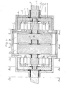
- Fig. 1 is a cross section of the turbines and planetary gears
- Fig. 2 A-A is a side view of the turbine assembly of Fig. 1
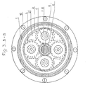
- Fig. 3 B-B is a cross section of the planetary gears of Fig. 1
- Fig. 4 C-C is a cross section of the planetary gear housing facing the turbine housing of Fig. 1
- Fig. 5 D-D is a cross section of the turbines of Fig. 1
- Fig. 6 E-E is a cross section of the planetary gear housing after the turbine of Fig.1
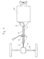
- Fig. 7 is the general layout of the system
- Fig. 8 is a cross section of the second embodiment of the turbine in Fig. 1
- In Fig. 1 and Fig. 2 A-A, the
planetary gear housing 1 houses the planetary gears. Theaxle 3 goes to the wheels and is splined into theinternal ring gear 4. Theplanetary gear shaft 7 is threaded into theturbine housing 14. Theaxle 3 is fitted into a bearing, bushing orspacer 13 which is fitted in thegear housing 1. The turbine housing 14 houses the two indepedent turbines. - In Fig. 3 B-B, the
planetary gear housing 1 houses theplanetary gears 6 consisting of theinternal ring gear 4 and the sun gear 8. The diagram shows the top plate of theplanet carrier 5, theplanetary gear shafts 7, and theturbine shaft 9. - In Fig. 4 C-C, the base plate of the planetary gear housing is also the turbine housing cover screwed together and the
turbine shaft 9 passes through the fitted bushing/bearing 12. - In Fig. 5 D-D, the turbines 2 and 2a are each fitted into bearings/bushings at the
turbine housing 14; theturbine shaft 9 is splined into the sun gear 8 and fitted into another bushing in the centre of theinternal ring gear 4. - One turbine (male) 2 is fitted into the centre bearing 11 of the other turbine (female) 2a. The bearings are fitted in such a way as to balance the turbines 2 and 2a within the planetary gears to reduce excess play.
- In Fig. 7 the
engine 100 powers a rotatinghydraulic pump 20 which pushes pressurized oil to the turbines by way of ahigh pressure hose 40 to aselector valve 30. When the selector valve is set in the forward drive position, the pressurized oil continues on through the high pressureflexible hose 70 to the turbines 2 and 2a which turn the planetary gears. The flexiblehigh pressure hose 60 now serves as a return hose and by way of this hose the oil passes through theselector valve 30 and continues through thereturn hose 50 back to the hydraulic pump. - When the
selector valve 30 is set for reverse, the pressurized oil goes through the flexiblehigh pressure hose 60 to the turbines which rotates the planetary gears and the power travels out on the output shafts; the pressurized oil continues out of the turbines 2 and 2a through the flexiblehigh pressure hose 70 which while in reverse becomes a return hose, to theselector valve 30 and continues back through thereturn hose 50 to the hydraulic pump. - The
turbine housing 14 supporting the turbines for rotation provides anupper channel 19 and alower channel 20 to allow the pressurized oil to surge into the turbines to rotate the said turbine in either direction as desired; - Fig. 8 is a second embodiment of the turbine in Fig. 1 showing a
channel divider 16 dividing the channel in two passages 19a and 19b the lower of the two passages 19b leads directly to the turbine blades and the other 19a continues over and beyond the lower passage without hesitation to the turbine blades. In the lower passage 19b the oil can strike the turbine directly on the curve of the blade causing an immediate surge forward but depending on the position of the blade, it can have a backward surge and at this point the upper passage 19a with its continuous even flow will compensate for the top dead centre.
Claims (5)
1. An axle driving system for a vehicle with power supplied by pressurized oil to rotate the vehicle driving wheels comprising in combination:
- two independent hydraulic turbines which are inter-engaged at their centres;
- the said turbines rotate in either direction and rotating power is transferred to turbine shafts, one from each turbine;
- the turbine shafts engage reduction gear sets on the wheel side of the turbines and the power is then transferred from the gear sets to output axle shafts;
- a turbine housing supporting the turbines for rotation provides an upper channel and a lower channel to allow the pressurized oil to surge into the turbines to rotate the said turbines in either direction as desired;
- a selector valve adapted to direct the pressurized oil into either the upper channel or the lower channel;
- the said channels each have a distinct function; the selection of the lower channel causes the turbines to rotate in a clockwise/forward direction thus achieving the reverse direction; the selection of the upper channel rotates the turbines in a counterclockwise direction.
2. An axle driving system as set forth in claim 1 wherein the reduction gear sets are planetary gears.
3. An axle driving system as set forth in claim 2 wherein the axle shafts are an extension of the related ring gears of the planetary gear sets.
4. An axle driving system as set forth in claims 2 or 3 wherein the turbine shafts are splined to the sun gears of the related planetary reduction gears.
5. An axle driving system as set forth in claim 1 in which the pressurized oil enters the turbine housing by way of the upper channel, a channel divider divides this upper channel in two passages; the lower of the two passages leads directly to the turbine blades and the other continues over and beyond the lower passage without hesitation or deadspot to the turbine blades, in the lower passage the oil can strike the turbine directly on the curve of the blade causing an immediate forward surge but depending on the position of the blade, it can have a backward surge and at this point the upper passage having a continuous even flow will compensate for the top dead centre.
Applications Claiming Priority (2)
| Application Number | Priority Date | Filing Date | Title |
|---|---|---|---|
| CA000535334A CA1237674A (en) | 1987-04-23 | 1987-04-23 | Hydraulic turbine system |
| CA535334 | 1987-04-23 |
Publications (2)
| Publication Number | Publication Date |
|---|---|
| EP0287801A2 true EP0287801A2 (en) | 1988-10-26 |
| EP0287801A3 EP0287801A3 (en) | 1990-04-04 |
Family
ID=4135479
Family Applications (1)
| Application Number | Title | Priority Date | Filing Date |
|---|---|---|---|
| EP88103961A Withdrawn EP0287801A3 (en) | 1987-04-23 | 1988-03-12 | Hydraulic turbine system |
Country Status (3)
| Country | Link |
|---|---|
| EP (1) | EP0287801A3 (en) |
| JP (1) | JPS63275819A (en) |
| CA (1) | CA1237674A (en) |
Cited By (2)
| Publication number | Priority date | Publication date | Assignee | Title |
|---|---|---|---|---|
| WO2001040683A1 (en) * | 1999-12-03 | 2001-06-07 | Oh Woong Bae | Torque converter |
| DE102012012500A1 (en) * | 2012-06-21 | 2013-12-24 | Volkswagen Aktiengesellschaft | Axle drive device for motor vehicle, has two transmission gears, where one of transmission gears is arranged between differential and respective output shaft in functionally effective manner |
Family Cites Families (6)
| Publication number | Priority date | Publication date | Assignee | Title |
|---|---|---|---|---|
| FR73133E (en) * | 1958-01-30 | 1960-09-23 | Groups of technically selected or improved devices for quality industrial vinification | |
| GB1232657A (en) * | 1968-05-24 | 1971-05-19 | ||
| JPS4912270A (en) * | 1972-05-17 | 1974-02-02 | ||
| GB1543607A (en) * | 1976-05-21 | 1979-04-04 | Trw Inc | Drive assembly |
| DE2706361C2 (en) * | 1977-02-12 | 1982-10-28 | geb. Chapman Bessie Lorraine Harlingen Tex. Caldwell | Hydraulic transmission |
| US4240515A (en) * | 1978-12-08 | 1980-12-23 | Kirkwood Robert W | Vehicle hydraulic drive system |
-
1987
- 1987-04-23 CA CA000535334A patent/CA1237674A/en not_active Expired
-
1988
- 1988-03-12 EP EP88103961A patent/EP0287801A3/en not_active Withdrawn
- 1988-03-14 JP JP5852588A patent/JPS63275819A/en active Pending
Cited By (2)
| Publication number | Priority date | Publication date | Assignee | Title |
|---|---|---|---|---|
| WO2001040683A1 (en) * | 1999-12-03 | 2001-06-07 | Oh Woong Bae | Torque converter |
| DE102012012500A1 (en) * | 2012-06-21 | 2013-12-24 | Volkswagen Aktiengesellschaft | Axle drive device for motor vehicle, has two transmission gears, where one of transmission gears is arranged between differential and respective output shaft in functionally effective manner |
Also Published As
| Publication number | Publication date |
|---|---|
| JPS63275819A (en) | 1988-11-14 |
| EP0287801A3 (en) | 1990-04-04 |
| CA1237674A (en) | 1988-06-07 |
Similar Documents
| Publication | Publication Date | Title |
|---|---|---|
| US10336187B2 (en) | Planetary power take off device | |
| US5730676A (en) | Three-mode, input-split hybrid transmission | |
| CA2012134C (en) | Power transmission | |
| FI93264B (en) | Hydrostatic mechanical power take-off | |
| US4442729A (en) | Lubricating system for four-wheel drive torque transfer mechanism | |
| US4342238A (en) | Automotive drive system with continuously variable transmission | |
| US7537536B2 (en) | Two speed gearbox | |
| JPS6228554A (en) | Variable speed transmission gear and/or transmission axle assembly | |
| US6001042A (en) | Continuously variable transmission with ratio synchronizing system | |
| US4283968A (en) | Housing assembly for electric vehicle transaxle | |
| US4296650A (en) | Two-speed transaxle | |
| US6599216B1 (en) | Gearbox unit | |
| US4841804A (en) | Automatic transmission for motor vehicles | |
| US4472984A (en) | Automatic planetary transmission | |
| EP0287801A2 (en) | Hydraulic turbine system | |
| US4825721A (en) | Method and apparatus for power transmission from an engine | |
| US4181040A (en) | Infinitely variable speed gear drive | |
| GB2237339A (en) | Variable transmission and engine fuel economiser each using differential gearing | |
| GB2058251A (en) | Automotive transmission with continuously variable speed mechanism | |
| EP0738846A2 (en) | Belt type continuously variable transmitting apparatus | |
| US4716786A (en) | Automatic transmission for motor vehicles | |
| JPS5852104B2 (en) | Automatic transmission for front wheel drive vehicles | |
| EP0181418A1 (en) | Planetary gear assembly | |
| US8721490B2 (en) | Planetary drive system | |
| US4455891A (en) | Power transmission configuration having continuous variable progression of gear reduction ratios |
Legal Events
| Date | Code | Title | Description |
|---|---|---|---|
| PUAI | Public reference made under article 153(3) epc to a published international application that has entered the european phase |
Free format text: ORIGINAL CODE: 0009012 |
|
| AK | Designated contracting states |
Kind code of ref document: A2 Designated state(s): DE FR IT |
|
| PUAL | Search report despatched |
Free format text: ORIGINAL CODE: 0009013 |
|
| AK | Designated contracting states |
Kind code of ref document: A3 Designated state(s): DE FR IT |
|
| RHK1 | Main classification (correction) |
Ipc: F16H 47/08 |
|
| STAA | Information on the status of an ep patent application or granted ep patent |
Free format text: STATUS: THE APPLICATION IS DEEMED TO BE WITHDRAWN |
|
| 18D | Application deemed to be withdrawn |
Effective date: 19901005 |