EP0287824B1 - Installation pour l'élevage des petits animaux, en particulier des volailles - Google Patents
Installation pour l'élevage des petits animaux, en particulier des volailles Download PDFInfo
- Publication number
- EP0287824B1 EP0287824B1 EP88104607A EP88104607A EP0287824B1 EP 0287824 B1 EP0287824 B1 EP 0287824B1 EP 88104607 A EP88104607 A EP 88104607A EP 88104607 A EP88104607 A EP 88104607A EP 0287824 B1 EP0287824 B1 EP 0287824B1
- Authority
- EP
- European Patent Office
- Prior art keywords
- supporting
- sections
- net
- floor
- support
- Prior art date
- Legal status (The legal status is an assumption and is not a legal conclusion. Google has not performed a legal analysis and makes no representation as to the accuracy of the status listed.)
- Expired - Lifetime
Links
- 241001465754 Metazoa Species 0.000 title claims description 17
- 244000144977 poultry Species 0.000 title claims description 4
- 230000000384 rearing effect Effects 0.000 title description 2
- 238000009434 installation Methods 0.000 title 1
- 238000004873 anchoring Methods 0.000 claims description 20
- 239000002184 metal Substances 0.000 claims description 13
- 229910052751 metal Inorganic materials 0.000 claims description 13
- 239000004033 plastic Substances 0.000 claims description 6
- 229920003023 plastic Polymers 0.000 claims description 6
- 241000287828 Gallus gallus Species 0.000 claims description 5
- 239000000853 adhesive Substances 0.000 claims description 3
- 230000001070 adhesive effect Effects 0.000 claims description 3
- 235000013330 chicken meat Nutrition 0.000 claims description 3
- 235000013594 poultry meat Nutrition 0.000 claims description 3
- 150000001875 compounds Chemical class 0.000 claims 2
- 229910000831 Steel Inorganic materials 0.000 claims 1
- 239000010959 steel Substances 0.000 claims 1
- 238000003860 storage Methods 0.000 description 5
- 238000004140 cleaning Methods 0.000 description 4
- 230000015572 biosynthetic process Effects 0.000 description 3
- 238000010276 construction Methods 0.000 description 3
- XEEYBQQBJWHFJM-UHFFFAOYSA-N Iron Chemical compound [Fe] XEEYBQQBJWHFJM-UHFFFAOYSA-N 0.000 description 2
- 238000004026 adhesive bonding Methods 0.000 description 2
- 235000013372 meat Nutrition 0.000 description 2
- 229920000728 polyester Polymers 0.000 description 2
- 238000003466 welding Methods 0.000 description 2
- 241000272517 Anseriformes Species 0.000 description 1
- 239000004952 Polyamide Substances 0.000 description 1
- 208000027418 Wounds and injury Diseases 0.000 description 1
- 210000000481 breast Anatomy 0.000 description 1
- 238000005253 cladding Methods 0.000 description 1
- 239000011248 coating agent Substances 0.000 description 1
- 238000000576 coating method Methods 0.000 description 1
- 230000000052 comparative effect Effects 0.000 description 1
- 230000006378 damage Effects 0.000 description 1
- 230000002349 favourable effect Effects 0.000 description 1
- 229920002457 flexible plastic Polymers 0.000 description 1
- 238000007654 immersion Methods 0.000 description 1
- 208000014674 injury Diseases 0.000 description 1
- 229910052742 iron Inorganic materials 0.000 description 1
- 235000000396 iron Nutrition 0.000 description 1
- 210000001503 joint Anatomy 0.000 description 1
- 230000002093 peripheral effect Effects 0.000 description 1
- 229920002647 polyamide Polymers 0.000 description 1
- 230000002787 reinforcement Effects 0.000 description 1
- 238000005096 rolling process Methods 0.000 description 1
- 238000007789 sealing Methods 0.000 description 1
- 239000013464 silicone adhesive Substances 0.000 description 1
- 229920002379 silicone rubber Polymers 0.000 description 1
- 239000004945 silicone rubber Substances 0.000 description 1
- 230000000087 stabilizing effect Effects 0.000 description 1
- 229910001220 stainless steel Inorganic materials 0.000 description 1
- 239000010935 stainless steel Substances 0.000 description 1
- 239000004753 textile Substances 0.000 description 1
Images









Classifications
-
- A—HUMAN NECESSITIES
- A01—AGRICULTURE; FORESTRY; ANIMAL HUSBANDRY; HUNTING; TRAPPING; FISHING
- A01K—ANIMAL HUSBANDRY; AVICULTURE; APICULTURE; PISCICULTURE; FISHING; REARING OR BREEDING ANIMALS, NOT OTHERWISE PROVIDED FOR; NEW BREEDS OF ANIMALS
- A01K45/00—Other aviculture appliances, e.g. devices for determining whether a bird is about to lay
- A01K45/005—Harvesting or transport of poultry
-
- A—HUMAN NECESSITIES
- A01—AGRICULTURE; FORESTRY; ANIMAL HUSBANDRY; HUNTING; TRAPPING; FISHING
- A01K—ANIMAL HUSBANDRY; AVICULTURE; APICULTURE; PISCICULTURE; FISHING; REARING OR BREEDING ANIMALS, NOT OTHERWISE PROVIDED FOR; NEW BREEDS OF ANIMALS
- A01K31/00—Housing birds
- A01K31/002—Poultry cages, e.g. transport boxes
- A01K31/007—Floors
-
- A—HUMAN NECESSITIES
- A01—AGRICULTURE; FORESTRY; ANIMAL HUSBANDRY; HUNTING; TRAPPING; FISHING
- A01K—ANIMAL HUSBANDRY; AVICULTURE; APICULTURE; PISCICULTURE; FISHING; REARING OR BREEDING ANIMALS, NOT OTHERWISE PROVIDED FOR; NEW BREEDS OF ANIMALS
- A01K31/00—Housing birds
- A01K31/22—Poultry runs ; Poultry houses, including auxiliary features, e.g. feeding, watering, demanuring
Definitions
- the invention relates to a device for keeping small animals, in particular poultry such as chickens, in a barn with a continuous, designed as a conveyor, grid-like plastic support floor made of longitudinal threads and transverse threads of a thin thread network, which is arranged transversely to the conveying direction of the same, with lateral conveying elements connected support profiles, wherein the network is connected by elastic members to the support profiles.
- Such a device is known from US-A-4,437,433, in which a web-shaped network serves as a supporting floor for the animals.
- the network covers support profiles which extend transversely to the conveying direction and which are designed as closed hollow profiles in cross section.
- For connection of the network with the support profile serve connecting elements which are pressed into the support profiles in the manner of a push button by clamping two longitudinal or transverse threads of the network.
- the support profiles are provided with holes at fixed intervals.
- the invention is therefore based on the object of improving the device of the type mentioned in the introduction in such a way that a technically favorable connection between the network and support profiles is achieved and a burden on the animals in the area of the support profiles is avoided.
- the elastic member for connecting the network to the support profile is designed as a strip-shaped, elastically flexible upholstery profile which extends above the same in the longitudinal direction of the support profile and with anchoring sections in the open top profile also extending in the longitudinal direction of the upholstery profile is anchored, the anchoring sections in the region of longitudinal threads of the network having recesses for the passage of the longitudinal threads.
- elastic cushion profiles extend over the entire length of the support profiles and are positively anchored in the support profiles which are open at the top. This advantageously ensures that the pressure load on the animals caused by support profiles is avoided.
- Another advantage of the device according to the invention results from the formation of recesses in the upholstery profiles.
- the network can be designed to be continuous along the conveyor path, the corresponding longitudinal threads of the network being arranged in the recesses.
- the device according to the invention achieves a noticeably better master result than known devices of a comparable type.
- the meat yield is about 7-10% higher. Furthermore, the meat is noticeably tender.
- the mesh threads preferably have a diameter of approximately (1-2) mm.
- the mesh size is preferably about (10-13) mm x (13-17) mm, in particular 12 mm x 15 mm.
- the mesh sheets were supported at 9 cm intervals by transverse support profiles. Accordingly, the pads assigned to the support profiles are spaced apart in the conveying direction.
- the pads are preferably in the form of continuous soft tubes. These enable the animals to be kept without the formation of breast bladders.
- the diameter of the "upholstery hose” is approximately (10 - 11) mm; the wall thickness about (1 - 2) mm, preferably about 1.5 mm. At the ends, the "upholstery hoses" are shot, for example by flattening, gluing, welding or the like.
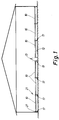
- a barn is shown in schematic cross section for receiving, for example, broiler chickens.
- a support floor 21 is arranged within the house above and at a distance from a house floor 12. This forms the running or standing area for the animals.
- a system of pipes, not shown, for the supply of feed troughs 27 extending in the conveying direction is provided above the support base 21.
- the supporting floor 21 is designed overall as a conveyor for the animals and - only interrupted by a central aisle 13 - is movable over the full width of the stables.
- the support base 21 is divided into individual webs, each of which is formed from a continuous, relatively thin thread network 10. These are expediently moved together and simultaneously in the conveying direction.
- the ends of the network tracks 10 run over deflection drums 14 (see FIGS. 5 to 9), the deflection drums 14 being connected on one side to a drive (not shown in more detail), the drive being preferably arranged in the region of the central aisle 13 in the present case.
- the support base 21 consists of a plurality of mesh webs 10 arranged next to one another, each of which is made of reinforced threads made of relatively soft or elastically flexible plastic, in particular polyamide, the reinforcement being formed by a heavy-duty core, for example a textile or metal wire is.
- the diameter of the mesh threads is approximately 1-2 mm, preferably only about 1 mm.
- the mesh size is in the range mentioned above and is preferably 12 mm x 15 mm.
- the network path designed in this way is led over transversely oriented support profiles 38 with simultaneous connection to them.
- the connection between the net track or the support floor network 10 and the support profile 38 is made by positive and / or non-positive fixing of the network 10 between the support profile 38 and an associated cushion, which on the top of the support floor 21 defined by the network 10 in each case above the assigned Support profile 38 is arranged.
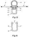
- the cushion is formed by a tubular or tubular hollow profile 40 (see FIG. 11 or 13).
- the support profiles 38 are each U-profiles made of plastic, metal, in particular stainless steel or the like, which are open at the top and between whose legs 36 and 37 the cushions associated with each support profile, here hollow profile 40, are anchored , with simultaneous fixation of the truss net 10 between the support profile 38 and cushion, namely hollow profile 40.
- the upper edges of the U-profile legs 36, 37 as well as those between them anchorable upholstery incisions through which the longitudinal threads of the truss floor net 10 extend in the assembled state.
- the incisions provided on the upper edges of the U-profile legs 36, 37 are identified by the reference number 15.
- the upholstery cuts corresponding to these are open at the bottom and are arranged in the anchoring region 25 of the upholstery.
- the distance between the mentioned incisions corresponds to the distance between the longitudinal threads of the truss net 10.
- the incision width is about 2 mm each, so that the longitudinal threads of the truss network 10 easily within the incisions 15 open at the top can be placed on the upper edges of the U-profile legs 36, 37 and within the downwardly open incisions in the region of the anchoring part 25 of the support profile upholstery.
- the edge incisions of the support profiles 38 and the downwardly open incisions in the anchoring area 25 of the support profile cushions are aligned with one another in the conveying direction or in the direction of the longitudinal mesh threads.
- the support profile upholstery comprises a tubular or tubular hollow profile 40, which extends over the top of the net 10, and continuously across the net track.
- the average outer diameter of the hollow profile 40 is approximately 10-11 mm.
- the wall thickness is approximately 1.5 mm.
- the hollow profile 40 is preferably made of silicone rubber with a Shore hardness of 60 degrees.
- a barbed anchoring region or section 25 is formed on the underside of the hollow profile 40. During assembly, this is brought into the area between the two legs 36, 37 of the support profile 38 designed as a U-profile, the area between the two legs 36 and 37 being filled beforehand with a silicone adhesive.
- the supporting floor networks or network tracks 10 are operatively connected to lateral conveying elements in the form of link chains 51.
- the operative connection is obtained in that the free ends of the support profiles 38 in the upright chain links the link chains arranged on both sides of each network path 10 are inserted and anchored by a split pin or the like.
- This type of operative connection between the truss floor network or network path 10 on the one hand and link chains 51 on the other hand is probably the simplest construction.
- the upper run of the webs 10 is supported by at least two guide profiles arranged on the longitudinal edge, here flat bars 16, which overlap at their abutting points.
- the support profiles 38 slide along these during transport of the web or the support floor network 10.
- the top of the flat iron 16 can be provided with a plastic covering to reduce sliding friction and to reduce noise, which is preferably replaceable.
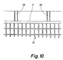
- the ends of the supporting floor network 10 to be connected to one another are each provided with a selvedge 11 (see FIG. 10), on which the butt joint is formed with the formation of an endless network path.
- support frameworks 17 extending in the conveying direction are provided on both sides of a net track 10. 3 are each formed by a double-T beam 18, on which two upright sheet metal walls 19 are placed, for example screwed on, the lower longitudinal edges of which are designed as lateral chain guide profiles 20 and on the upper, butt-ending ones Longitudinal edges a holder 31 for a feed trough 27 extending in the conveying direction is connected, in particular welded.
- the double-T beam 18, which extends in the conveying direction lies with its one transverse web on the barn floor 12 and is preferably screw-connected to it.
- the two upright Sheet metal walls 19 are attached to the upper crossbar of the double-T beam 18, preferably also by means of screws.
- the lower chain guide profiles 20 are designed so that they support both the upright and the transversely extending chain links of the link chains 51, downwards and to the side.
- chain guide profiles 30 are also laterally arranged on the sheet metal walls 19, namely screwed on.
- the chain guide profiles 30 are designed as so-called piling or double-angle profiles.
- each support frame 17 each have a length which is less than the total length of the support base 21.
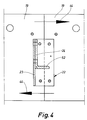
- the sheet metal walls formed in this way are butted to one another, the connection being effected by upright L-angles 22 (see FIGS. 3 and 4), to whose laterally inwardly projecting legs 23 cross members 24 are connected, which bring about a transverse stiffening of adjacent support structures 17. In this way, an extremely stable or rigid support frame for the support floor 21 is obtained.
- the upper chain guide profiles 30 extend between the cross members 24 and the holder 31 for the feeding trough 27, preferably in each case just below the mentioned holder 31 that the (Upright) chain links can move freely between the chain guide profile 30 and the holder 31 for the feeding trough 27 (see FIG. 3).
- the connecting brackets 22 are screwed to the butt-jointed sheet metal walls 19, as can be seen in FIG. 4.
- the crossbeams 24 used for transverse bracing are also screwed to the legs 23 projecting laterally inwards and the L-angle 22 (see also FIG. 4).
- the supporting floor nets or net tracks 10, together with supporting profiles 38, the distance of which in the conveying direction is preferably about 9 cm, are guided on the end of the supporting floor via deflection drums 14, each of which has sprockets 42 on the end face for deflecting the link chains 51 assigned to the supporting floor nets or mesh tracks 10.
- the deflection drums 14 are mounted on the lateral support frames 17.
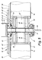
- the deflection drums 14 of adjacent support floor networks or net tracks 10 arranged at the same end of the support floor 21 are arranged coaxially to one another and supported by a common rotary bearing 50 which is formed on the common support frame 17 (see FIG . 5 to 9).
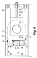
- FIGS. 8 and 9 show the corresponding mounting on the side opposite the drive side, on which a net tensioning device is additionally provided . Corresponding parts of these two bearings are provided with the same reference numerals to simplify the illustration.
- the deflection drums 14 are accordingly each formed by a tube 39, which are closed at the end by end flanges 41.
- a chain wheel 42 is connected to each of these end flanges 41, the teeth of which engage in the chain links extending parallel to the network path plane.
- the upright chain links are guided laterally by an annular projection 43 arranged on the sprocket 42.
- the sprockets 42 are each connected to the end flanges 41 by a plurality of screw bolts 35 arranged uniformly distributed over the circumference.
- adjacent deflection drums 14 have a common rotary bearing 50, which in the area of the common support structure 17 is arranged.
- the common rotary bearing 50 is formed in each case by a bearing bolt 45, which connects the adjacent deflection drums 14 in a rotationally fixed manner, and a bearing body 52 assigned to the latter.
- the bearing body 52 is integrated in the support frame 17.
- the rotationally fixed connection between the two deflection drums 14 on the one hand and the bearing pin 45 on the other hand is made by parallel keys 46 which are arranged between the bearing pin 45 and the two mutually facing sprockets 42.
- This embodiment allows the deflection drums 14 to be simply plugged onto the common bearing bolt 45. This allows the device to be assembled in sections by simply plugging and screwing it onto one another.
- the bearing pin 45 is slidingly supported in the bearing body 52.
- roller bearings are also possible.
- the bearing body 52 in the embodiment shown is a relatively flat metal plate with a through bore 26, the peripheral surface of which defines the plain bearing surface. This bearing plate is fastened to the supporting structure 17 by means of screw bolts 28, 29, specifically in the area between two upright sheet metal walls 19, the support being carried downwards on the continuous double-T beam 18 (see FIGS. 5 and 7).
- FIGS. 8 and 9 The common mounting of adjacent deflection drums 14 at the end of the support base 21 opposite the drive side is shown schematically in FIGS. 8 and 9.
- This storage differs from the storage described with reference to FIGS. 5 to 7 only in that the bearing body 52 is adjustable in the direction parallel to the conveying direction with appropriate tension or pretensioning of the supporting floor network or the network tracks 10.
- the bearing body 52 is designed as a slider, which with the help of a clamping screw 32 in Direction parallel to the conveying direction of the tray 21 can be adjusted.
- the clamping screw 32 is supported on the common support frame 17, specifically via a transverse yoke 33 and a yoke plate 34 fastened to the support frame 17, which is connected to the support frame 17 in the same way as the bearing body 52 in the embodiment according to FIGS. 5 to 7.
- Transverse yoke 33 and yoke plate 34 are screwed together by means of screw bolts 35 extending parallel to the conveying direction.
- the direction of movement of the supporting floor network or the network web 10 is indicated in FIGS. 7 and 9 with the arrows 44.
- the direction of movement of the supporting floor network or the network web 10 is shown in FIGS. 4 and 7 with the arrows 44.
- the bearing of the deflection drums 14 is designed in accordance with the bearing described, namely as a single and not as a double bearing, as shown with reference to FIGS. 5 to 9.
- the chain wheels 42 With a pitch circle diameter of the chain wheels 42 connected to the deflection drums 14 of approximately 140-150 mm, the chain wheels 42 each have approximately five teeth.
- the outer diameter of the deflection drums 14 is approximately 135 mm in the dimensioning of the chain wheels 42 mentioned.
- the width of the supporting floor nets 10 is then about 2 m.
- the upper run of such a wide network floor is supported by six flat irons 16 of the type described, which are arranged at the same distance from one another (see FIG. 2).
- the support profile according to FIGS. 13 and 14 is slightly modified. Instead of connecting the top 13 and 14, a positive snap connection is provided between the support profile 38 on the one hand and an anchoring section 49 formed on the underside of the hollow body profile 40 on the other.
- the support profile 38 which is U-shaped in cross section, is provided at intervals with inwardly molded lugs or projections 53 which, in the assembled state, grip behind the waisted anchoring section 49 by clamping.
- An adhesive connection can be omitted in this embodiment.
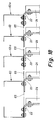
- the support profiles 38 are designed as C-profiles. Similar to the embodiment according to FIGS. 13 and 14, a positive snap connection is provided between the support profile 38 on the one hand and an anchoring section 49 formed on the underside of the hollow body profile 40 on the other hand.
- This comprises support lips 66 formed diametrically to the longitudinal center plane, which in the assembled state bear against the inside of the two legs of the C-shaped support profile 38 with the hollow body profile 40 being clamped on the support profile 38.
- sealing lips 67 are integrally formed on the anchoring section 49 of the hollow body profile 40 diametrically to its longitudinal center plane. Tolerance differences in the supporting floor network 10 can be compensated for by the gap spaces identified in FIG. 15 with the reference number 68. Furthermore, this allows the hollow body profile 40 to be pressed into the support profile 38 from above until it is anchored to it.
- the anchoring section 49 of the hollow body profile 40 is provided with recesses 69 arranged at a longitudinal distance from one another, the distance corresponding to the mesh size of the supporting floor network 10. Through these recesses In the assembled state, the longitudinal threads 70 of the truss floor network 10 extend through them. The transverse threads 71 of the supporting floor network 10 are shown in FIG. 15. These are assigned to lateral recesses in the area of the support profiles 15 or hollow body profiles 40, taking into account the above-mentioned play 68 for tolerance compensation.
- the bearing body 52 is preferably split, with an approximately extending dividing plane, the half facing the support floor 21 being fixedly connected to the device, while that after outside bearing half is detachably fixed by screws.
- the chain wheels 42 can also be designed as simple gear wheels.
- the deflection drums arranged opposite the drive side can preferably be tensioned independently of one another by assigning a separate tensioning device with a tensioning bearing to each deflection drum.
- the deflection drums are of course also pivoted independently of one another. In this way, different dimensional tolerances of the conveyor chains can be compensated.
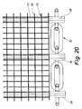
- FIGS. 17 to 20 Another embodiment of the device according to the invention is to be explained in more detail with reference to FIGS. 17 to 20, parts already described with reference to the previous embodiment and identified by the same reference numerals to avoid repetitions being no longer explained.
- the embodiment according to FIGS. 17 to 20 differs from the embodiment described above primarily in the different support of the support base 21.
- the support is carried out at a distance in the conveying direction Uprights 63, 63a arranged from one another, which are connected to one another by butt-jointed sheet metal walls 65, similar to the embodiment according to FIGS. 3 and 4, the transverse stiffening of adjacent support structures 17 of this type also being carried out by crossbeams 24, as shown in FIG. 3 and 4.
- every second support 63a is formed with wider legs, which are used for the butt connection of the sheet metal cladding 65.
- both the upper run and lower run of the chain 51 assigned to the support profiles 38 are guided within U-shaped chain guide profiles 64, which extend in the conveying direction and are fastened, namely screwed, to the support frame 17.
- These chain guide profiles each have mutually facing guide grooves for the upright chain links, the cross section of the guide grooves 86 being formed at right angles in the embodiment shown.
- the upright supports 63, 63a are each at a distance of approximately 1.2 to 1.8, in particular approximately 1.5 m.
- the connection between the support profiles 38 and the conveyor chains 51 is carried out in a similar manner as in the embodiment described above.
- a preferred construction of the network web 10 is as follows: In the weft direction: high-strength polyester monofilament threads (seven pieces with a thread spacing of 12.86 mm); in warp direction: high-strength polyester multifilament threads (five pieces; thread spacing 17.55 mm).
- the net formed in this way is preferably provided with a coating of soft PVC by immersion in a PVC paste.
- a feed trough 27 extending in the conveying direction is fastened to the upper side of the supporting structure 17 or to the upper end faces of the supporting supports 63, 63a. It has been found that this feed trough is too large or, as a rule, too high for small animals due to its design. Furthermore, not inconsiderable feed losses have been found because larger animals throw feed out of the trough 27.
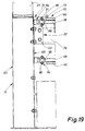
- a horizontally extending, also continuous feed catch plate 72 is arranged next to the feed trough 27, as is shown schematically in FIG. 19. This chuck 72 is of course also suitable and intended for the embodiment described above.
- the longitudinal edge of the feed catch plate 72 facing away from the feed trough 27 is provided with an elastically flexible cushion strip 73 corresponding to the hollow body profile 40 for the support profiles 38.
- the feed catch plate 72 is used as a feed channel for small animals. For larger animals, the feed tray serves to catch feed thrown out of the trough 27. This significantly reduces feed losses.
- the chuck plate 72 extends, as shown in FIG. 19, to the supporting floor 21 or to the net track 10.
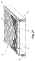
- FIGS. 21 to 24 An embodiment with a stationary support base 21 is described with reference to FIGS. 21 to 24, which is also defined by a continuous network path 10 of the type described.
- This embodiment is suitable for the rearing of animals that remain in the barn for a long time, e.g. B. chickens and hens or ducks. The effort of a movable supporting floor is not necessary for this.
- a rectangular frame 75 is positioned on wall bases 74 which are spaced apart and extend parallel to one another.
- the frame 75 serves as a base for the supporting floor 21.
- This can be of a similar size as in the previous embodiments.
- the basic structure of network 10 / support profiles 38 and hollow body profiles 40 is carried out in the same manner as in the embodiments according to FIGS. 1 to 20.
- the frame 75 is defined by double-T profiles 76 which rest on the wall bases 74 and which are connected to one another by cross members 24 which are arranged at a distance from one another.
- the cross member 24 are thus L-shaped profiles. The distance between these profiles is about 2.5 to 3.5 m, preferably about 3.0 m.
- double tabs 77 are welded to the webs, in particular on the mutually facing sides of the webs of the double-T profiles 76 at the stated distance from one another, between which the upright leg of the crossmember 24 can be fitted.
- the double straps 77 are each penetrated by a transversely directed support bolt 78, on which the cross members 24 are suspended.
- the cross members 74 each have downwardly open recesses 79 at their ends without cross legs, as shown in FIG. 22.
- the cross members 24 can thus be pivoted or folded upward about the supporting bolts 78.
- the net-like supporting floor 21 must be removed, ie rolled up. In this way, the barn floor between adjacent wall bases 74 is freely accessible for cleaning.
- the supporting structures assigned to it are each folded up on the double T profile 76 assigned to this wall base for the purpose of cleaning and are connected and held together in the folded-up position. In this way, cleaning of the barn floor on both sides of the central wall base is possible at the same time.
- the support base 21 is constructed correspondingly as in the previously described embodiments, i. H. with support profiles 38, mesh sheet 10 and upholstery or hollow body profiles 40 assigned to the support profiles 38.
- the front ends of the support profiles 38 are no longer associated with hollow body profiles 40.
- the ends of the support profiles 38 freed from these hollow body profiles 40 are accommodated in associated holding profiles 80, which are each fastened to the top of the double-T profiles 76.
- These holding profiles 80 are each defined by a U-profile which has recesses 81 tapering at a distance from one another in order to receive the front ends of the supporting profiles 38. The distance between the recesses 81 is accordingly the distance between the support profiles 38.
- the holding profiles 80 are covered at the top by a likewise U-shaped cover profile 82 which, with the legs directed downward, enters the holding profile 80 which is open at the top due to the corresponding dimensions.
- transverse bolts 83 are provided in the holding profile 80. These enable the cover profile 82 to be connected to the holding profile 80 in the manner of a bayonet connection 84 (see FIG. 24).
- the top of the cover profile 82 is provided with an elastic hollow body cover 85, which is intended to avoid injury to the animals through the cover profile 82.
- the cover profile 82 is first lifted to clean the barn after the bayonet connection 84 mentioned has been loosened accordingly.
- the net track together with the support profiles 38 is then removed, for. B. rolled up. This rolling up is facilitated by the trapezoidal recesses 81 according to FIG. 23.
- the cross members 24 can be folded up around the support bolts 78.
- the stable floor is then exposed for cleaning.
- the web 10 is preferably cleaned outside the stable.
- the support base 21 is then reassembled, in reverse order.
- the recesses 81 described are each in the upright legs of the U-shaped holding profile 80.
- the support profiles 38 are held within the recesses 81 by the upper cover profile 82.
Landscapes
- Life Sciences & Earth Sciences (AREA)
- Environmental Sciences (AREA)
- Birds (AREA)
- Animal Husbandry (AREA)
- Biodiversity & Conservation Biology (AREA)
- Zoology (AREA)
- Housing For Livestock And Birds (AREA)
- Road Paving Structures (AREA)
Claims (14)
- Dispositif pour l'élevage de petits animaux, en particulier de volaille engraissée comme des poulets, dans un bâtiment comportant un plancher porteur en matière synthétique (21), continu, en un genre de grille, réalisé sous la forme d'un convoyeur, et constitué de fils longitudinaux (70) et de fils transversaux (71) d'un filet (10) à fins fils qui repose sur des profilés porteurs (38) agencés transversalement à la direction de transport du filet et reliés à des organes latéraux de transport (51), le filet (10) étant relié par des organes élastiques aux profilés porteurs (38), caractérisé en ce que l'organe élastique pour la liaison du filet (10) au profilé porteur (38) est réalisé sous la forme d'un profilé d'amortissement (40) en forme de bande, élastiquement flexible, qui s'étend dans la direction longitudinale du profilé porteur (38) audessus de celui-ci et qui est ancré dans le profilé porteur (38), ouvert au-dessus, par des tronçons d'ancrage (25, 49) qui s'étendent aussi dans la direction longitudinale du profilé d'amortissement (40), les tronçons d'ancrage (25, 49) présentant dans la zone de fils longitudinaux (70) du filet (10) des évidements (69) pour le passage des fils longitudinaux (70).
- Dispositif suivant la revendication 1, caractérisé en ce que les profilés porteurs (38) sont réalisés sous la forme de profilés en U ouverts vers le haut, en matière synthétique, en métal, de préférence en acier allié, etc., les tronçons d'ancrage (25, 49) des profilés d'amortissement (40) étant ancrés entre des ailes (36, 37) des profilés porteur (38).
- Dispositif suivant la revendication 1 ou 2, caractérisé en ce que les profilés porteurs (38) sont réalisés sous la forme de profilés en forme de C avec lesquels les profilés d'amortissement (40) sont ancrés, pour réaliser une liaison par la forme, par l'intermédiaire de tronçons d'ancrage (49) façonnés.
- Dispositif suivant la revendication 3, caractérisé en ce que les tronçons d'ancrage (49) présentent des lèvres d'appui (66) qui sont appuyées du côté interne, avec une action de serrage, sur les deux ailes du profilé porteur (38).
- Dispositif suivant la revendication 1 ou 2, caractérisé en ce que les profilés d'amortissement (40) sont ancrés par leurs tronçons d'ancrage (25) dans les profilés porteurs (38) au moyen de masses d'enrobage (masses adhésives).
- Dispositif suivant la revendication 2, caractérisé en ce que des ailes (36, 37) des profilés porteurs (38) en forme de U s'étendent jusque dans le plan du filet (10) et présentent des découpes (15) pour le passage de fils longitudinaux (70) du filet (10).
- Dispositif suivant la revendication 2, caractérisé en ce que les ailes (36, 37) des profilés porteurs (38) en forme de U sont munies de saillies (53), façonnées vers l'intérieur, pour l'ancrage des tronçons d'ancrage (49) par une liaison par la forme.
- Dispositif suivant une ou plusieurs des revendications 1 à 7, caractérisé en ce que les organes latéraux de transport sont des chaînes sans fin (51) à maillons dont les maillons dressés sont fixés aux profilés porteurs (38).
- Dispositif suivant une ou plusieurs des revendications 1 à 8, caractérisé en ce que les organes de transport réalisés sous la forme de chaînes à maillons (51) sont guidés dans des profilés de guidage réalisés de façon correspondante, en particulier des profilés en U (64) comportant des rainures de guidage (86), tournées l'une vers l'autre, pour les maillons de chaîne qui s'étendent verticalement, ou des profilés à double cornière (20, 30) pour le soutien tant des maillons de chaîne verticaux qu'aussi de ceux qui s'étendent transversalement à cela, des profilés de guidage (30) de ce genre étant adjoints au moins au brin supérieur des chaînes à maillons (51).
- Dispositif suivant une ou plusieurs des revendications 1 à 9, caractérisé en ce que le filet de plancher porteur ou la bande de filet (10) y compris les profilés porteurs (38) sont guidés du côté des extrémités du plancher porteur par des tambours de renvoi (14) qui sont montés de préférence sur les supports latéraux (17) et qui présentent du côté frontal chaque fois une roue à chaîne (42) pour le renvoi des chaînes à maillons (51) adjointes au filet de plancher porteur ou à la bande de filet (10) et en ce que, de ces chaînes, au moins une peut être accouplée à un entraînement motorisé.
- Dispositif suivant la revendication 10, comportant au moins deux filets de plancher porteur, ou bandes de filet (10), agencés l'un près de l'autre, en réalisant un plancher porteur (21) agrandi de façon correspondante, caractérisé en ce que les tambours de renvoi (14), agencés à la même extrémité du plancher porteur (21), pour des filets de plancher porteur ou bien des bandes de filet (10) contigus sont agencés coaxialement l'un à l'autre et sont soutenus sur leurs côtés tournés l'un vers l'autre par un palier commun qui est réalisé de préférence sur le support (17) commun aux deux bandes de filet.
- Dispositif suivant la revendication 11, caractérisé en ce que le palier commun (50) est formé par un tourillon de palier (45), qui relie l'un à l'autre rigidement en torsion les tambours de renvoi contigus (14), et par un corps de palier (52), de préférence divisible, adjoint à ce tourillon et supporté par le support commun (17).
- Dispositif suivant l'une des revendications 10 à 12, caractérisé en ce que le filet de plancher porteur ou la bande de filet (10) peut être tendu dans la direction de transport par un réglage correspondant d'au moins un des tambours de renvoi (14) ou de son palier (50) dans une direction parallèle à la direction de transport, des tambours de renvoi (14) agencés l'un à côté de l'autre pouvant être de préférence réglés indépendamment l'un de l'autre.
- Dispositif pour l'élevage de petits animaux, en particulier de volaille engraissée comme des poulets, dans un bâtiment comportant un plancher porteur (21) continu, en un genre de grille, en matière synthétique, qui est soutenu par des profilés porteurs (38) agencés à distance l'un de l'autre et s'étendant chaque fois parallèlement l'un à l'autre et qui est formé par une bande continue d'un filet (10) à fils relativement fins relié par des organes élastiques aux profilés porteurs (38) et posé sur un socle ou cadre (75) et enroulable au besoin, caractérisé en ce que le cadre (75) est formé par des tronçons de cadre qui au besoin peuvent être rabattus vers le haut le long d'un côté du cadre après une suppression préalable du plancher porteur (21) et en ce que sur le côté supérieur du plancher porteur sont chaque fois agencés au-dessus des profilés porteurs (38) des coussins mous, élastiquement flexibles, en particulier en forme de corps creux ou profilés creux (40) qui ont une forme de tube ou de boyau.
Priority Applications (1)
| Application Number | Priority Date | Filing Date | Title |
|---|---|---|---|
| AT88104607T ATE90506T1 (de) | 1987-04-23 | 1988-03-23 | Einrichtung fuer die haltung von kleintieren, insbesondere von mastgefluegel, wie haehnchen. |
Applications Claiming Priority (4)
| Application Number | Priority Date | Filing Date | Title |
|---|---|---|---|
| DE3713611A DE3713611C2 (de) | 1987-04-23 | 1987-04-23 | Einrichtung für die Haltung von Kleintieren, insbesondere Mastgeflügel, wie Hähnchen |
| DE3713611 | 1987-04-23 | ||
| DE19883807137 DE3807137C2 (de) | 1988-03-04 | 1988-03-04 | Einrichtung für die Haltung von Kleintieren, insbesondere Mastgeflügel, wie Hähnchen |
| DE3807137 | 1988-03-04 |
Publications (2)
| Publication Number | Publication Date |
|---|---|
| EP0287824A1 EP0287824A1 (fr) | 1988-10-26 |
| EP0287824B1 true EP0287824B1 (fr) | 1993-06-16 |
Family
ID=25854876
Family Applications (1)
| Application Number | Title | Priority Date | Filing Date |
|---|---|---|---|
| EP88104607A Expired - Lifetime EP0287824B1 (fr) | 1987-04-23 | 1988-03-23 | Installation pour l'élevage des petits animaux, en particulier des volailles |
Country Status (3)
| Country | Link |
|---|---|
| EP (1) | EP0287824B1 (fr) |
| DE (1) | DE3881746D1 (fr) |
| ES (1) | ES2042624T3 (fr) |
Families Citing this family (2)
| Publication number | Priority date | Publication date | Assignee | Title |
|---|---|---|---|---|
| CA2930480A1 (fr) | 2015-05-26 | 2016-11-26 | Life-Science Innovations, Llc | Systeme de conteneurs empilables destine a la volaille et methode |
| CN108684573A (zh) * | 2017-04-05 | 2018-10-23 | 青岛合正源农牧装备有限公司 | 一种活禽交易市场粪便自动收集设备 |
Family Cites Families (3)
| Publication number | Priority date | Publication date | Assignee | Title |
|---|---|---|---|---|
| DE2703968C2 (de) * | 1977-02-01 | 1984-11-15 | Nagel, Hans-Joachim, Dr., 6380 Bad Homburg | Einrichtung zur Aufzucht von Geflügel in einem Stall |
| DE3042043A1 (de) * | 1980-11-07 | 1982-05-27 | Nagel, Hans-Joachim, Dr., 2800 Bremen | Einrichtung fuer die haltung von mastgefluegel |
| US4437433A (en) * | 1982-01-26 | 1984-03-20 | U. S. Industries, Inc. | Poultry broiler cage |
-
1988
- 1988-03-23 EP EP88104607A patent/EP0287824B1/fr not_active Expired - Lifetime
- 1988-03-23 DE DE8888104607T patent/DE3881746D1/de not_active Expired - Fee Related
- 1988-03-23 ES ES88104607T patent/ES2042624T3/es not_active Expired - Lifetime
Also Published As
| Publication number | Publication date |
|---|---|
| ES2042624T3 (es) | 1993-12-16 |
| DE3881746D1 (de) | 1993-07-22 |
| EP0287824A1 (fr) | 1988-10-26 |
Similar Documents
| Publication | Publication Date | Title |
|---|---|---|
| EP0051844B1 (fr) | Plancher pour poulailler | |
| EP3241433B1 (fr) | Système de maintien de volaille et procédé de transport d' oeufs dans un système de maintien de volaille | |
| DE2555357A1 (de) | Batterie zur aufzucht von broilern | |
| DE69401292T2 (de) | Verschiebbares Fressgitter | |
| DE3020742A1 (de) | Bodenanordnung | |
| DE3713611C2 (de) | Einrichtung für die Haltung von Kleintieren, insbesondere Mastgeflügel, wie Hähnchen | |
| DE3735350A1 (de) | Einrichtung zur zuechtung von kleintieren | |
| DE2921821C2 (de) | Vorrichtung zur seitlichen Begrenzung eines Viehstandes | |
| DE3807137C2 (de) | Einrichtung für die Haltung von Kleintieren, insbesondere Mastgeflügel, wie Hähnchen | |
| DE69501138T2 (de) | Randabdichtung für Pendelbodenförderer | |
| DE60200757T2 (de) | Geflügelhauseinrichtung und verfahren zum betrieb einer solcher geflügelhauseinrichtung | |
| EP0287824A1 (fr) | Installation pour l'élevage des petits animaux, en particulier des volailles | |
| DE60208320T2 (de) | Führung für hin- und hergehende Latten eines Flurförderers | |
| DE1607222B1 (de) | Kaefiganordnung fuer Legehennen | |
| WO1997025857A1 (fr) | Dispositif d'evacuation du fumier pour etable a canaux de collecte du fumier evacues mecaniquement | |
| DE2703968A1 (de) | Einbau fuer einen stall zur haltung von insbesondere mast-gefluegel | |
| DE102022101743B4 (de) | Futterketten-Spannvorrichtung und Fütterungsanlage | |
| EP0007320A1 (fr) | Installation pour l'élevage de volaille de chair dans des poulaillers | |
| DE2014088C2 (de) | Viehstand, insbesondere Rindviehstand | |
| DE202025107952U1 (de) | Reinigungsvorrichtung für eine Stallbucht und Stall umfassend mindestens zwei Stallbuchten mit der Reinigungsvorrichtung | |
| DE1607222C (de) | Käfiganordnung für Legehennen | |
| DE3911722A1 (de) | Verfahren sowie transportsystem zum ein- und/oder ausstallen von gefluegel | |
| DE6803561U (de) | Vorrichtung zur viehfuetterung | |
| DE2007478A1 (de) | Batterie Aufzuchtkafig fur Kleinvieh | |
| DE7115665U (de) | Käfig fur eine Käfigbatterie zur Auf nähme von Geflügel |
Legal Events
| Date | Code | Title | Description |
|---|---|---|---|
| PUAI | Public reference made under article 153(3) epc to a published international application that has entered the european phase |
Free format text: ORIGINAL CODE: 0009012 |
|
| AK | Designated contracting states |
Kind code of ref document: A1 Designated state(s): AT BE CH DE ES FR GB IT LI NL SE |
|
| 17P | Request for examination filed |
Effective date: 19890405 |
|
| 17Q | First examination report despatched |
Effective date: 19900719 |
|
| GRAA | (expected) grant |
Free format text: ORIGINAL CODE: 0009210 |
|
| AK | Designated contracting states |
Kind code of ref document: B1 Designated state(s): AT BE CH DE ES FR GB IT LI NL SE |
|
| REF | Corresponds to: |
Ref document number: 90506 Country of ref document: AT Date of ref document: 19930715 Kind code of ref document: T |
|
| REF | Corresponds to: |
Ref document number: 3881746 Country of ref document: DE Date of ref document: 19930722 |
|
| GBT | Gb: translation of ep patent filed (gb section 77(6)(a)/1977) |
Effective date: 19930628 |
|
| ITF | It: translation for a ep patent filed | ||
| ET | Fr: translation filed | ||
| REG | Reference to a national code |
Ref country code: ES Ref legal event code: FG2A Ref document number: 2042624 Country of ref document: ES Kind code of ref document: T3 |
|
| PGFP | Annual fee paid to national office [announced via postgrant information from national office to epo] |
Ref country code: FR Payment date: 19940330 Year of fee payment: 7 Ref country code: AT Payment date: 19940330 Year of fee payment: 7 |
|
| PGFP | Annual fee paid to national office [announced via postgrant information from national office to epo] |
Ref country code: SE Payment date: 19940415 Year of fee payment: 7 |
|
| PLBE | No opposition filed within time limit |
Free format text: ORIGINAL CODE: 0009261 |
|
| STAA | Information on the status of an ep patent application or granted ep patent |
Free format text: STATUS: NO OPPOSITION FILED WITHIN TIME LIMIT |
|
| PGFP | Annual fee paid to national office [announced via postgrant information from national office to epo] |
Ref country code: BE Payment date: 19940427 Year of fee payment: 7 |
|
| 26N | No opposition filed | ||
| EAL | Se: european patent in force in sweden |
Ref document number: 88104607.2 |
|
| PG25 | Lapsed in a contracting state [announced via postgrant information from national office to epo] |
Ref country code: AT Effective date: 19950323 |
|
| PG25 | Lapsed in a contracting state [announced via postgrant information from national office to epo] |
Ref country code: SE Effective date: 19950324 |
|
| PG25 | Lapsed in a contracting state [announced via postgrant information from national office to epo] |
Ref country code: BE Effective date: 19950331 |
|
| BERE | Be: lapsed |
Owner name: NAGEL HANS-JOACHIM Effective date: 19950331 |
|
| PG25 | Lapsed in a contracting state [announced via postgrant information from national office to epo] |
Ref country code: FR Free format text: LAPSE BECAUSE OF NON-PAYMENT OF DUE FEES Effective date: 19951130 |
|
| EUG | Se: european patent has lapsed |
Ref document number: 88104607.2 |
|
| REG | Reference to a national code |
Ref country code: FR Ref legal event code: ST |
|
| PGFP | Annual fee paid to national office [announced via postgrant information from national office to epo] |
Ref country code: GB Payment date: 19990325 Year of fee payment: 12 |
|
| PGFP | Annual fee paid to national office [announced via postgrant information from national office to epo] |
Ref country code: CH Payment date: 19990329 Year of fee payment: 12 |
|
| PG25 | Lapsed in a contracting state [announced via postgrant information from national office to epo] |
Ref country code: GB Free format text: LAPSE BECAUSE OF NON-PAYMENT OF DUE FEES Effective date: 20000323 |
|
| PG25 | Lapsed in a contracting state [announced via postgrant information from national office to epo] |
Ref country code: LI Free format text: LAPSE BECAUSE OF NON-PAYMENT OF DUE FEES Effective date: 20000331 Ref country code: CH Free format text: LAPSE BECAUSE OF NON-PAYMENT OF DUE FEES Effective date: 20000331 |
|
| GBPC | Gb: european patent ceased through non-payment of renewal fee |
Effective date: 20000323 |
|
| REG | Reference to a national code |
Ref country code: CH Ref legal event code: PL |
|
| PGFP | Annual fee paid to national office [announced via postgrant information from national office to epo] |
Ref country code: ES Payment date: 20020321 Year of fee payment: 15 |
|
| PGFP | Annual fee paid to national office [announced via postgrant information from national office to epo] |
Ref country code: NL Payment date: 20020328 Year of fee payment: 15 Ref country code: DE Payment date: 20020328 Year of fee payment: 15 |
|
| PG25 | Lapsed in a contracting state [announced via postgrant information from national office to epo] |
Ref country code: ES Free format text: LAPSE BECAUSE OF NON-PAYMENT OF DUE FEES Effective date: 20030324 |
|
| PG25 | Lapsed in a contracting state [announced via postgrant information from national office to epo] |
Ref country code: NL Free format text: LAPSE BECAUSE OF NON-PAYMENT OF DUE FEES Effective date: 20031001 Ref country code: DE Free format text: LAPSE BECAUSE OF NON-PAYMENT OF DUE FEES Effective date: 20031001 |
|
| NLV4 | Nl: lapsed or anulled due to non-payment of the annual fee |
Effective date: 20031001 |
|
| REG | Reference to a national code |
Ref country code: ES Ref legal event code: FD2A Effective date: 20030324 |
|
| PG25 | Lapsed in a contracting state [announced via postgrant information from national office to epo] |
Ref country code: IT Free format text: LAPSE BECAUSE OF NON-PAYMENT OF DUE FEES;WARNING: LAPSES OF ITALIAN PATENTS WITH EFFECTIVE DATE BEFORE 2007 MAY HAVE OCCURRED AT ANY TIME BEFORE 2007. THE CORRECT EFFECTIVE DATE MAY BE DIFFERENT FROM THE ONE RECORDED. Effective date: 20050323 |