EP0287845A2 - Dispositif pour transformer un courant de récipients à plusieurs voies en plusieurs files de récipients parallèles séparées entre elles par des éléments de division - Google Patents
Dispositif pour transformer un courant de récipients à plusieurs voies en plusieurs files de récipients parallèles séparées entre elles par des éléments de division Download PDFInfo
- Publication number
- EP0287845A2 EP0287845A2 EP88104886A EP88104886A EP0287845A2 EP 0287845 A2 EP0287845 A2 EP 0287845A2 EP 88104886 A EP88104886 A EP 88104886A EP 88104886 A EP88104886 A EP 88104886A EP 0287845 A2 EP0287845 A2 EP 0287845A2
- Authority
- EP
- European Patent Office
- Prior art keywords
- conveyor
- transition section
- arrangement according
- conveying direction
- conveyor belts
- Prior art date
- Legal status (The legal status is an assumption and is not a legal conclusion. Google has not performed a legal analysis and makes no representation as to the accuracy of the status listed.)
- Granted
Links
Images


Classifications
-
- B—PERFORMING OPERATIONS; TRANSPORTING
- B65—CONVEYING; PACKING; STORING; HANDLING THIN OR FILAMENTARY MATERIAL
- B65B—MACHINES, APPARATUS OR DEVICES FOR, OR METHODS OF, PACKAGING ARTICLES OR MATERIALS; UNPACKING
- B65B21/00—Packaging or unpacking of bottles
- B65B21/02—Packaging or unpacking of bottles in or from preformed containers, e.g. crates
- B65B21/04—Arranging, assembling, feeding, or orientating the bottles prior to introduction into, or after removal from, containers
-
- B—PERFORMING OPERATIONS; TRANSPORTING
- B65—CONVEYING; PACKING; STORING; HANDLING THIN OR FILAMENTARY MATERIAL
- B65G—TRANSPORT OR STORAGE DEVICES, e.g. CONVEYORS FOR LOADING OR TIPPING, SHOP CONVEYOR SYSTEMS OR PNEUMATIC TUBE CONVEYORS
- B65G47/00—Article or material-handling devices associated with conveyors; Methods employing such devices
- B65G47/22—Devices influencing the relative position or the attitude of articles during transit by conveyors
- B65G47/26—Devices influencing the relative position or the attitude of articles during transit by conveyors arranging the articles, e.g. varying spacing between individual articles
Definitions
- the invention relates to an arrangement for converting a multi-lane, densely packed container stream into a plurality of parallel rows of containers, each separated from one another by dividing elements, with a feed conveyor serving to convey the containers, with a discharge conveyor which is parallel to and at a distance from one another by the ones running in its conveying direction arranged dividing elements is divided into several aisles for each row of containers and has a greater width compared to the conveying width of the feed conveyor, and with a transition section preceding the discharge conveyor, which is formed by upper lengths in the conveying direction of a plurality of conveyor belts arranged next to one another transversely to this conveying direction and in which the containers of the multi-lane flow of containers are distributed to the individual streets.
- Multi-lane, densely packed container stream in the sense of the invention is to be understood as a container stream in which the containers are either actually densely packed in several lanes or rows, i. H. are present on their circumferential surfaces against one another or, at least from the design of the element conveying this container flow, there is the possibility that the containers can also directly touch different rows or tracks on their circumferential surfaces.
- "separate rows of containers” are understood to mean those in which the containers of each row of containers are each taken up by an alley formed on the conveyor and the containers of an alley are separated from the containers of an adjacent alley by a dividing element.
- An arrangement of the type described at the outset serves, in particular, to supply the rows of containers required for a container packing machine from a conveyed container stream form.
- the containers are fed as a single-track container flow to a container static table which is formed by a plurality of conveyor belts arranged next to one another and driven endlessly and whose conveying direction is perpendicular to the conveying direction of the feed conveyor, so that the containers experience a change in motion of 90 ° when transferred to the container storage table.
- the conveyor belts forming the container stowage table are arranged parallel to one another over the entire length of the storage table, so that adjacent conveyor belts are also at a very short distance from one another over the entire length of the container stowage table.
- the containers After the containers have been handed over from the feed conveyor, they form on the container table to form a more or less densely packed container flow, in which the following containers are also pressurized against the preceding containers and which is limited by two lateral guide rails that determine the conveying width of the container table .
- the containers After passing a transition section, in the course of which the conveying width of the container stowage table increases, the containers are moved into a plurality of aisles formed at the end of the container stowage table and each separated from one another by dividing elements or dividing walls and thus forming a plurality of rows of containers which are separated from one another.
- the number of lanes is equal to the number of lanes that the container stream has before reaching the transition section or while passing this transition section.
- the known arrangement is an unconditional requirement that the containers at least the outer traces of the multi-lane flow of containers through subsequent containers to the side depressed, as well as those containers which do not enter a lane by chance after passing the transition section, are deflected or threaded into the nearest lane by the pressure of the subsequent containers.
- An essential, function-related disadvantage of the known arrangement is therefore first of all that impacts between the individual containers, in particular also in the region of the transition section and when threading into the individual alleys, and a resulting high noise pollution cannot be avoided.
- a disadvantage of the known arrangement is that it cannot be ruled out by threading the containers under pressure into the individual lanes that several containers wedge against one another at the inlet, for example of an alley, such that threading the containers into this lane is not possible. For the aforementioned reasons, the performance that can be achieved with the known arrangement is also limited.
- the object of the invention is to develop an arrangement of the type described in the introduction in such a way that the conveyed flow of containers into the separate rows of containers is shaped without impact and pressure.
- an arrangement according to the invention is designed such that the conveyor belts forming these divide apart in the course of the transition section in such a way that the lateral distance between the upper lengths of adjacent conveyor belts increases with increasing distance from the feed conveyor, and that the maximum value of these distances, however is in each case smaller than the diameter of the containers or the width of the lanes formed on the discharge conveyor.
- the containers, in particular bottles, fed to the transition section are not only moved in the conveying direction in the course of the transition section, but these containers are also left transverse to the conveying direction by the conveyor belts Fende movement component imprinted, so that the container stream is spread to the width required for insertion or threading into the alleys of the conveyor solely by the conveyor belts forming the transition section and not by the pressure of subsequent containers.
- the supply of the supplied container flow to the individual streets formed on the discharge conveyor is thus pressure-free and shock-free and, above all, also low-noise.
- the arrangement according to the invention is also a significantly higher output (containers processed per unit of time) possible. This also contributes to the fact that, in the arrangement according to the invention, the containers are already supplied as a multi-lane container flow via the feed conveyor.
- the conveyor belts forming the transition section are already part of the feed conveyor.
- the conveyor belts forming the transition section are elements independent of the feed conveyor, in which case the feed conveyor is also formed by a plurality of conveyor belts arranged next to one another is, the number of conveyor belts forming the transition section is greater than the number of conveyor belts of the feed conveyor.
- At least the transition section is formed by a large number of very narrow conveyor belts.
- This embodiment has the advantage that even with an arrangement in which the width of the lanes formed on the discharge conveyor can be adjusted to suit containers of different diameters, an optimal mode of operation is ensured, regardless of the width of these lanes set, because of the very narrow width Formation of the conveyor belts of the transition section, at least one conveyor belt of this type is located at the beginning of each lane between the one-piece elements there delimiting this lane.
- the conveyor belts forming the transition section continue preferably into the area of the discharge conveyor, i.e. these conveyor belts also form its conveyor belts at least over a partial length of the removal conveyor following the transition section.
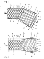
- FIGS. 1 and 2 has a feed conveyor 1a, a discharge conveyor 2a and a transition section 3a, the latter being formed between the end of the feed conveyor 1a and the beginning of the discharge conveyor 2a.
- the feed conveyor 1a essentially consists of four self-contained and endlessly driven conveyor belts or hinge belt chains 4, which, with their upper length extending in the direction of conveyance A of the conveyor 1a, directly adjacent to one another transversely to the direction of conveyance A. are arranged and with these upper lengths form a substantially horizontal footprint for upright bottles or containers 5.
- the hinged belt chains 4 are driven in a revolving manner by means of a drive 8 and are guided at the beginning and end of the feed conveyor 1a, ie where this feed conveyor 1a merges into the transition section 3a, via deflection rollers or wheels (not shown).
- the feed conveyor 1a Transversely to the direction of conveyance A, the feed conveyor 1a is delimited on both sides by a guide rail 6.
- the conveying width of the feed conveyor 1a is defined by the distance between the two guide railings 6.
- the again essentially horizontal standing area for the containers 5 is formed by the upper lengths of a total of six flat top chains 7, in this embodiment the flat top chains 7 continuing in the area of the conveyor 2a and with their upper lengths there as well form the base for the container 5.
- the hinged belt chains 7 are likewise closed in themselves and driven endlessly, for which purpose the hinged belt chains 7 at the transition area between the feed conveyor 1a and the transition section 3a and at the right end of the discharge conveyor 2a, which is no longer shown in FIGS.
- each via deflection rollers or - wheels are guided, of which the deflection wheels provided at the end of the discharge conveyor 2a are driven by a drive corresponding to the drive 8 such that the flat top chains 7 move with their respective upper lengths in the conveying direction A.
- baffle plate 9 At the transition area between the feed conveyor 1a and the transition section 3a there is a stationary baffle plate 9, which is approximately level with its standing surface formed by the hinged belt chains 4 and 7 with its upper, horizontal surface and one at the transition area between the feed conveyor 1a and the transition section 3a stationary base for the container 5 forms.
- the baffle plate 9 lies with its front edge 9 ⁇ in the conveying direction A and with its rear edge 9 ⁇ in the conveying direction A each perpendicular to the conveying direction A.
- the rear edge of the baffle plate 9 can also be formed by two sections running obliquely to the conveying direction A, which merge into one another in the middle of the conveying width of the transition section 3a and enclose an angle with one another which either opposes the conveying direction A or opens in the direction of conveyance A, as is indicated in FIG. 2 at 9 ′′′ or 9 underbrochen with broken lines.
- the two guide rails 6 in the area of the transition section 3a are each guided symmetrically to the central axis of the transition section 3a running in the conveying direction A, so that the distance between the two guide rails is in the course of the transition section 3a and in the conveying direction A. 6 increases and these guide railings 6, which also form the lateral boundary of the discharge conveyor 2a, have a greater distance from one another in the region of the discharge conveyor 2a than in the region of the feed conveyor, i. H. the width of the discharge conveyor 2a is greater than the width of the feed conveyor 1a.
- the top straps 7 are guided with their upper lengths in the area of the transition section 3a by guide means (not shown) in such a way that the top lengths of the top straps 7 start from the transition area between the feed conveyor 1a and the transition section 3a, i. H.
- a total of five intermediate railings or partitions 10 are provided between the two guide railings 6 in the embodiment shown, each of which runs parallel to one another and at a distance from one another in the conveying direction A. and the conveyor 2a in six lanes 11, each with the same Divide width, of which the two outer lanes 11 are laterally delimited by one of the guide railings 6 and a one-piece wall 10 and the inner lanes 11 by one-piece walls 10.
- the standing surfaces for the containers 5 in the alleys 11 are each formed by the upper length of a flat chain 7.
- the containers 5 are fed via the feed conveyor 1a as a densely packed, multi-lane container flow, in which the containers 5, at least at the end of the feed conveyor 1a, not only lie directly against one another with their peripheral surface, but are also offset from one another in a honeycomb-like manner that each container 5 of a row or track of the multi-lane container flow is offset by half the container diameter from the containers of an adjacent row of this container flow.
- the baffle plate 9 this formation of the containers 5 at the end of the feed conveyor 1a is ensured in any case, since the containers standing on the baffle plate 9 are only conveyed or pushed forward by subsequent containers.
- the containers 5 Since the hinge belt chains 7 preferably rotate at a somewhat higher speed than the hinge belt chains 4, the containers 5 form a loosened container flow after passing through the baffle plate 9 at the transition section 3a, which flow is also formed in its formation can be influenced, which has the rear edge in the conveying direction 9 ⁇ , 9 ′′′ or 9 ⁇ of the baffle plate 9. Due to the course described, which the upper lengths of the flat top chains 7 have in the region of the transition section 3, the containers 9 in the transition section 3a are also moved transversely to the conveying direction A, namely the outer container 5 more than the inner container 5.
- the loosened container flow is thus also spread in width, so that the containers 5 then finally move smoothly into the alleys 11 of the discharge conveyor 2 and form there in several, ie in the illustrated embodiment, six parallel rows of containers.
- a bumpless, pressure-free and, above all, low-noise conversion of the densely packed container flow into the rows of containers in the alleys 11 is achieved.
- the use of the baffle plate 9 ensures that a tightly packed container flow is present at least at the end of the feeder 1a, even if there are gaps in the container flow being conveyed, that is to say there are the same conditions there, even with possibly smaller gaps in the container flow being conveyed optimal distribution of the container 5 lead to the individual streets 11.
- FIG. 3 differs from the embodiment according to FIGS. 1 and 2 essentially only in that instead of separate flat top chains 4 and 7, flat top chains 12 are used for the feed conveyor 1b, the discharge conveyor 2b and the intermediate section 3b, which extend with their upper lengths, which in turn form the standing surfaces for the containers 5, from the feed conveyor 1b to the discharge conveyors 2b.
- the upper lengths of the flat top chains 12 are again diverged like a fan in this embodiment such that the distance x between the upper lengths of two adjacent flat top chains 12 increases in the conveying direction A and the upper lengths of the flat top chains 12 in their Transition section 3a forming area have the flat S-shaped course that has already been described for the hinge band chains 7 in the area of the transition section 3a.
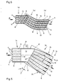
- Figures 4 and 5 show an embodiment which differs from the embodiment according to Figures 1 and 2 essentially only in that the transition section 3c and the discharge conveyor 2c in this embodiment do not connect in line to the feed conveyor 1c, but the conveying direction B.
- the transition section 3c and the discharge conveyor 3c with the conveying direction A of the feed conveyor 1c enclose an angle a which in the embodiment shown is greater than 40 ° but less than 90 ° and opens in both conveying directions A and B.
- a baffle plate 13 is provided in this embodiment, which basically corresponds to the baffle plate 9 in FIGS. 1 and 2 in terms of its function and design, the baffle plate 13, however, having an essentially trapezoidal cut such that the extensions of the front edge 13 ⁇ in the conveying direction and the rear edge 13 ⁇ in the conveying direction enclose an angle b which is equal to the angle a, so that the edge 13 ⁇ is perpendicular to the conveying direction B.
- the two guide railings 6 are curved at 6 ⁇ . Otherwise, the design according to FIGS.
- FIGS. 4 and 5 corresponds in terms of its construction and function to the design according to FIGS. 1 and 2, so that in FIGS. 4 and 5 again the same reference numerals as in FIGS. 1 and 2 for such elements are used, which correspond to the elements of Figures 1 and 2.
- a special feature of the embodiment according to FIGS. 4 and 5 is present compared to the embodiments according to FIGS. 1-3 in that the width of this transition path is inevitably greater due to the transition path 3c adjoining the feed conveyor 1c at an angle than the conveyor width of the feed conveyor 1c, which is also documented by the greater length of the edge 13 ⁇ compared to the edge 13 ⁇ , so that the container stream can fan out laterally after passing through the baffle plate 13.
- FIG. 6 A design similar to that in FIGS. 4 and 5 is shown in FIG. 6, with in this embodiment the feed conveyor 1d only having four flat top chains 4 and the discharge conveyor 2d and the transition section 3d being formed by five flat top chains 7.
- the number of hinge belt chains 7 forming the transition section and the conveyor is also greater in the embodiment according to FIG. 6, namely in the examples shown by ONE greater than the number of hinge belt chains forming the feed conveyor 4.
- the hinge belt chains 7 and thus also their upper lengths forming the horizontal standing surfaces for the containers 5 using guides, not shown in more detail are curved in an arc in the horizontal plane in the initial region of the discharge conveyor 2d, so that the transition section 3d adjoins the feed conveyor 1d at an angle, i. H. the conveying directions A of the feed conveyor 1d and the conveying direction B of the transition section 3d enclose the already mentioned angle a, but the discharge conveyor 2d with its longitudinal extension or conveying direction A ⁇ is parallel to the longitudinal extension or conveying direction A of the feed conveyor 1d.
- the maximum distance x that the upper lengths of adjacent hinge belt chains 7 and 12 have from one another at the start of the conveyor 2a, 2b, 2c and 2d is not only significantly smaller than the diameter of the container 5 or . whose floor areas, but also much smaller than the width of the alleys 11th
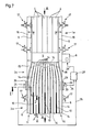
- FIGS. 7 to 9 A preferred embodiment is shown in FIGS. 7 to 9, in which the feed conveyor 1e is in turn formed by five flat top chains 4. While the hinge belt chains used for the feed conveyor, the discharge conveyor and the transition section each have the same width in the direction perpendicular to the conveying direction in the above-described embodiments, in the embodiment according to FIGS. 7 to 9 the discharge conveyor 2e there and the transition section 3e there Hinged belt chains 14 are used, which have a significantly smaller width than the hinge belt chains 4. According to the design of the guide plate 15 shown in FIG.
- a total of twelve flat top chains 14 are provided in this embodiment, which in turn are closed and driven endlessly in such a way that the upper lengths of the flat top chains 14 forming the horizontal standing surfaces for the containers 5 circulate in the conveying direction A of the feed conveyor 1e, which is also the conveying direction of the transition section 3e and the discharge conveyor 2e.
- the hinged belt chains 14 are guided over deflection wheels or rollers (not shown in more detail).
- the flat top chains 14 are also guided at the end of the discharge conveyor 2e, which is no longer shown in FIG. 7, via deflection rollers which are driven by a drive, also not shown.
- the upper lengths of adjacent flat top chains 14 are located directly next to one another at the transition area between the feed conveyor 1e and the transition section 3e transversely to the conveying direction A, the top lengths of the flat top chains 14 then being connected at this transition area symmetrical to the central axis of the transition section 3e running in the conveying direction A such that the distance x ⁇ by the upper lengths of two adjacent hinge belt chains 14 have from each other, increases in the course of the transition path 3e and in the conveying direction.
- the hinged belt chains 14 not only form the horizontal standing surface for the containers 5 in the region of the transition section 3e, but also the standing surfaces for the containers in the region of the discharge conveyor 2e or in the region of the alleys 11 there.
- the embodiment according to FIGS. 7 to 9 again corresponds to the embodiment according to FIGS. 1 and 2, i.e. the container flow conveyed via the feed conveyor 1e, in which the containers 5 have the formation shown in FIG. 1 and already six pre-formed rows in the conveying direction, is loosened after passing through the baffle plate 9 at the transition section 3e and by the special course that the have upper lengths of the conveyor belts 14 on the transition section 3e, also spread transversely to the conveying direction A, so that the containers 5 enter the individual lanes 11 of the conveyor 2e and form there to form the parallel rows of containers.
- the maximum distances x ⁇ which the upper lengths of adjacent hinge chain chains 14 have from one another, are in turn significantly smaller than the diameter of the containers 5 and also significantly smaller than the width of the lanes 11.
- these are first held on a machine frame 16 of the feed conveyor 1e with the aid of setting elements 17.
- These adjusting elements 17 allow the associated guide rail 6 to be adjusted in the horizontal direction and perpendicular to the conveying direction A, as indicated by the double arrows C.
- the outer guide railings 6 can be adjusted by the adjusting elements 17 in the horizontal direction and perpendicular to the conveying direction A on the machine frame 18 common to the discharge conveyor 2e and the transition section 3e.
- the threaded rods 19 offset in the direction of conveyance A are arranged at a vertical distance above the upper lengths of the flat top chains 14, which is greater than the height of the largest containers 5 to be processed, so that the containers 5 can move freely underneath the threaded rods 19.
- each threaded rod 19 is held at both ends on the free end of a holding arm 20 which projects in the vertical direction over the guide rail 6 there and is fastened to this guide rail.
- each threaded rod 19 is fixed to the associated holding arm 20 by two nuts 21.
- the individual partitions 10 are held in accordance with FIG. 9 hanging on the threaded rods 19, namely in that each partitions 10 for each threaded rod 19 has a holding arm 22 projecting beyond its upper edge in the vertical direction, which at its free, upper end Has bore through which the associated threaded rod 19 is passed.
- the holding arms 22 and thus the partitions 10 are fixed on the respective threaded rod 19 again by means of two nuts 23. After loosening the nuts 21 and 23, the outer guide railings 6 can be adjusted according to the diameter of the containers 5 to be processed with the aid of the adjusting elements 17 and also the partitions 10. After each adjustment, the nuts 21 and 23 are tightened again.
- two accumulation detectors 24 are provided on the transition section 3e, specifically one such accumulation detector 24 on each outer guide rail 6 in the conveying direction A with a certain distance in front of the transition area between the transition section 3e and the subsequent discharge conveyor 2e.
- These traffic jams 24 are used to switch off the drive motor 8 for the flat top chains 4 of the feed conveyor 1e when the containers 5 jam in the region of the transition section 3e due to an overflow of the alleys 11 or for other reasons.
- the two congestion detectors 24 are each connected via a line 25 or 26 to an electrical control device 27, which is connected via a control line 28 to the drive motor 8 and then switches it off when one of the two congestion detectors 24 or both congestion detectors 24 are actuated.
- FIG. 9 shows one of the two traffic jams 24 in more detail. It essentially consists of a plate 29 which is arranged horizontally with its surface sides and which has at least one holding arm 30 which projects above the upper side in the vertical direction and is fastened to the plate 29 and with which the plate 29 is held in a freely oscillating manner on the associated guide rail 6.
- the holding arm 30, which for this purpose has a bore at its upper, free end, through which the shaft of a holding screw anchored on the guide rail 6 extends with great play, is located outside the movement space of the container 5 delimited by the guide rail 6.
- the plate 29, the is lower than the lower edge of the guide rail 6, which extends in the conveying direction A, with an edge region 29 ⁇ into this movement space of the container 5, and only to the extent that the edge region 29 ⁇ during normal operation of the The arrangement does not come into contact with the containers 5.
- a contact-free signal transmitter is provided on the guide rail 6 by means of a holder 32, which interacts with the plate 29 or with the holding arm 30 of this plate made of metal.
- the guide plate 15 is used, which is arranged with its upper, lying in a horizontal plane on the machine frame 18 directly below the upper lengths of the flat top chains 14, so that the individual links of the flat top chains 14 plates 14 ⁇ slide on this surface with their underside.
- the surface 34 several, ie a total of twelve guide grooves 35 are introduced in the embodiment shown, each extending over the entire length of the guide plate 15 running in the conveying direction A and being arranged next to one another perpendicular to this length or to the conveying direction A.
- the guide grooves 35 are also on the transverse sides 36 and 37 of the guide plate 15, which (transverse sides) run perpendicular to the conveying direction A and of which the transverse side 36 is located at the transition region between the feed conveyor 1e and the transition path 3e and Transverse side 37 in the area of the transition between the transition section 3e and the discharge conveyor 2e are open.
- the course of the guide grooves 35 corresponds to the course that the upper lengths of the flat top chains 14 have in the region of the transition section 3e and at the transition to the conveyor 2e, ie the center-to-center distance between two adjacent guide grooves 35 is approximately the same in the region of the transverse side 36 Width of the hinge band chains 14 or the width which the plates 14 ⁇ have perpendicular to the direction of movement of the hinge band chains 14, while in the area of the transverse side 37 this center-center distance between two adjacent guide grooves 35 is larger by the amount x ⁇ than on the transverse side 36. As shown in FIG.
- the guide grooves 35 also have the flat S-shaped course which is typical for the course of the flat top chains 14, this course being such a guide groove 35 which is at a greater distance from the central plane M of the guide plate lying in the conveying direction A. 15 have, is much more pronounced than in such guide grooves 35 that this central level ne M are closer.
- a guide groove 35 is provided for each hinge band chain 14, into which guide elements provided on the underside of the plates 14 ⁇ of this hinge band chain 14 and projecting beyond the underside engage. The latter are formed by the lugs 38 which are provided in any case on flat top chains on the individual plates 14 ⁇ , on which the individual plates 14 ⁇ are connected to one another in an articulated manner to form the respective flat top chain 14.
- the guide plate 15 is made of a hard plastic. In principle, it is of course also possible to manufacture the guide plate 15 from plastic only in the region of the guide grooves 35 or at the edges delimiting the guide grooves on which the plates 14 ⁇ slide.
Landscapes
- Engineering & Computer Science (AREA)
- Mechanical Engineering (AREA)
- Attitude Control For Articles On Conveyors (AREA)
- Branching, Merging, And Special Transfer Between Conveyors (AREA)
- Supplying Of Containers To The Packaging Station (AREA)
- Containers Having Bodies Formed In One Piece (AREA)
- Warehouses Or Storage Devices (AREA)
Priority Applications (1)
| Application Number | Priority Date | Filing Date | Title |
|---|---|---|---|
| AT88104886T ATE70506T1 (de) | 1987-03-30 | 1988-03-26 | Anordnung zum umformen eines mehrspurigen behaelterstroms in mehrere parallele, jeweils durch einteilelemente voneinander getrennte behaelterreihen. |
Applications Claiming Priority (2)
| Application Number | Priority Date | Filing Date | Title |
|---|---|---|---|
| DE3710528 | 1987-03-30 | ||
| DE19873710528 DE3710528A1 (de) | 1987-03-30 | 1987-03-30 | Anordnung zum umformen eines mehrspurigen behaelterstroms in mehrere parallele, jeweils durch einteilelemente voneinander getrennte behaelterreihen |
Publications (3)
| Publication Number | Publication Date |
|---|---|
| EP0287845A2 true EP0287845A2 (fr) | 1988-10-26 |
| EP0287845A3 EP0287845A3 (en) | 1989-05-10 |
| EP0287845B1 EP0287845B1 (fr) | 1991-12-18 |
Family
ID=6324371
Family Applications (1)
| Application Number | Title | Priority Date | Filing Date |
|---|---|---|---|
| EP88104886A Expired - Lifetime EP0287845B1 (fr) | 1987-03-30 | 1988-03-26 | Dispositif pour transformer un courant de récipients à plusieurs voies en plusieurs files de récipients parallèles séparées entre elles par des éléments de division |
Country Status (7)
| Country | Link |
|---|---|
| US (1) | US4844234A (fr) |
| EP (1) | EP0287845B1 (fr) |
| JP (1) | JPS63288814A (fr) |
| AT (1) | ATE70506T1 (fr) |
| BR (1) | BR8801431A (fr) |
| DE (2) | DE3710528A1 (fr) |
| ES (1) | ES2029294T3 (fr) |
Cited By (6)
| Publication number | Priority date | Publication date | Assignee | Title |
|---|---|---|---|---|
| EP0392331A1 (fr) * | 1989-04-14 | 1990-10-17 | D. Swarovski & Co. | Bande de maintien pour pierres précieuses ou autres petits articles |
| EP0982248A1 (fr) * | 1998-08-28 | 2000-03-01 | IWK Verpackungstechnik GmbH | Dispositif de transport pour une machine d'emballage |
| ITMI20082213A1 (it) * | 2008-12-12 | 2010-06-13 | Ocme Srl | Dispositivo selezionatore di gruppi di oggetti per l'alimentazione a macchine confezionatrici e relativo metodo di selezione |
| EP2361859A1 (fr) * | 2010-02-26 | 2011-08-31 | Schober GmbH Werkzeug- und Maschinenbau | Dispositif d'augmentation d'un intervalle transversal des pièces |
| CN103723492A (zh) * | 2013-12-20 | 2014-04-16 | 楚天科技股份有限公司 | 一种输瓶装置 |
| EP3771656A1 (fr) * | 2019-07-30 | 2021-02-03 | SCHOTT Schweiz AG | Conditionnement de transport pour récipients et procédé de déballage de récipients |
Families Citing this family (29)
| Publication number | Priority date | Publication date | Assignee | Title |
|---|---|---|---|---|
| US4895245A (en) * | 1988-07-06 | 1990-01-23 | Standard-Knapp, Inc. | Round container orienting system |
| JP2534493Y2 (ja) * | 1989-10-31 | 1997-04-30 | 三菱重工業株式会社 | びん集合コンベア装置 |
| DE4114875A1 (de) * | 1991-05-07 | 1992-11-12 | Seitz Enzinger Noll Masch | Anordnung zum umformen eines angefoerderten mehrspurigen und dicht gepackten behaelterstroms in mehrere parallele, jeweils durch einteilelemente voneinander getrennte behaelterreihen |
| US5778634A (en) * | 1996-11-07 | 1998-07-14 | Standard-Knapp, Inc. | Product infeed line pressure controlling apparatus for packer |
| US5768860A (en) * | 1996-11-07 | 1998-06-23 | Standard-Knapp, Inc. | Round product divider for packaging line |
| DE19751967B4 (de) * | 1997-11-24 | 2005-07-14 | Brauerei Beck Gmbh & Co. | Einrichtung insbesondere zur Gasseneinteilung bzw. zum Transport,von Transportgut,z. B. Flaschen, Getränkedosen und dergleichen |
| JP2001225029A (ja) * | 2000-02-18 | 2001-08-21 | Hiroshi Maeda | オンライン内部品質検査用搬送装置 |
| US6843360B2 (en) | 2002-03-27 | 2005-01-18 | Douglas Machine, Inc. | Retractable transfer device metering apparatus and methods |
| US6837360B2 (en) | 2002-06-19 | 2005-01-04 | Douglas Machine, Inc. | Retractable transfer device metering and product arranging apparatus and methods |
| DE10255814A1 (de) * | 2002-11-29 | 2004-06-09 | Khs Maschinen- Und Anlagenbau Ag, Patentabteilung | Vorrichtung zum Aufteilen und Auseinanderführen eines Behälterstromes |
| US6793064B2 (en) * | 2003-02-12 | 2004-09-21 | Douglas Machine, Inc. | Retractable transfer device metering and product arranging and loading apparatus and methods |
| NL1022955C2 (nl) * | 2003-03-17 | 2004-10-01 | Blueprint Automation B V | Samenstel en werkwijze voor het verzamelen van verschillende goederen. |
| US7073656B2 (en) * | 2004-10-21 | 2006-07-11 | Douglas Machine, Inc. | Method and apparatus for removing holes from nested product patterns |
| US7416073B1 (en) * | 2007-02-09 | 2008-08-26 | Geo. M. Martin Company | Diverting flat belt support system |
| DE202008009166U1 (de) | 2008-07-08 | 2008-10-30 | Krones Ag | Transportvorrichtung zum Zuführen von Artikeln zu einer Verpackungsmaschine |
| EP2627592B1 (fr) | 2010-10-15 | 2015-01-28 | Sanofi-Aventis U.S. LLC | Appareil et procede pour charger des articles |
| US9090411B2 (en) | 2010-10-15 | 2015-07-28 | Sanofi-Aventis U.S. Llc | Apparatus and method for loading and unloading containers |
| DE102010050129A1 (de) * | 2010-11-03 | 2012-05-03 | Khs Gmbh | Transportvorrichtung zum Transportieren von Behältern |
| US9663306B2 (en) * | 2014-04-10 | 2017-05-30 | Flexible Steel Lacing Company | Conveyor transfer guards |
| US10233035B2 (en) | 2014-04-10 | 2019-03-19 | Flexible Steel Lacing Company | Conveyor transfer guards |
| CN104085671B (zh) * | 2014-06-23 | 2017-01-18 | 楚天科技股份有限公司 | 冻干机多行进料系统及其进料方法 |
| CN108146705A (zh) * | 2017-12-29 | 2018-06-12 | 泉州市汉威机械制造有限公司 | 一种产品输送分路装置 |
| CN108438322B (zh) * | 2018-05-14 | 2023-08-18 | 温州海航机械有限公司 | 全自动多列四边封一次性餐具包装机的牙签分料装置 |
| CN110406888B (zh) * | 2019-08-02 | 2020-10-30 | 泸州品创科技有限公司 | 瓶子输送方法 |
| CN110626767B (zh) * | 2019-09-29 | 2024-02-06 | 深圳赛动生物自动化有限公司 | 培养瓶滚动传输机构及传输方法 |
| CN110789972B (zh) * | 2019-10-18 | 2021-04-27 | 湖南大用智能科技有限公司 | 叠加物料分离系统及物料分离设备 |
| CN111846882A (zh) * | 2020-07-22 | 2020-10-30 | 江苏宇航食品科技有限公司 | 一种瓶装奶用玻璃瓶自动排列输送机构 |
| CA3193208A1 (fr) | 2020-09-22 | 2022-03-31 | Flexible Steel Lacing Company | Bloqueur d'espace de transporteur a rouleaux |
| CN113978810A (zh) * | 2021-11-18 | 2022-01-28 | 台山市远博机械科技有限公司 | 一种碗碟杯合流输送设备 |
Citations (1)
| Publication number | Priority date | Publication date | Assignee | Title |
|---|---|---|---|---|
| DE1267592B (de) | 1964-12-04 | 1968-05-02 | Enzinger Union Werke Ag | Mehrbahniger Flaschenstautisch fuer Flascheneinpackmaschinen |
Family Cites Families (13)
| Publication number | Priority date | Publication date | Assignee | Title |
|---|---|---|---|---|
| US2769522A (en) * | 1954-02-03 | 1956-11-06 | Fred B Pfeiffer | Conveyor and stretching means |
| FR72844E (fr) * | 1958-01-24 | 1960-07-22 | Remy & Cie E P | Procédé d'aménagement de machine ou installation pour manipuler les bouteilles, et machines ou installations en comportant application |
| US3095960A (en) * | 1959-11-20 | 1963-07-02 | Sig Schweiz Industrieges | Device for arranging irregularly supplied flat articles |
| CH404520A (de) * | 1963-07-05 | 1965-12-15 | Sig Schweiz Industrieges | Vorrichtung zum Einstellen einer Aufnahmevorrichtung bezüglich einer ausgerichteten Reihenanordnung von Gegenständen, die auf einem bewegten Förderband liegen |
| US3379350A (en) * | 1963-12-31 | 1968-04-23 | Nat Biscuit Co | Article conveying, separating and stacking apparatus |
| US3552537A (en) * | 1968-07-22 | 1971-01-05 | Barry Wehmiller Co | Container flow control conveyer system |
| US3675755A (en) * | 1970-05-04 | 1972-07-11 | Northern Electric Co | Orienting and feeding small discs |
| US3860232A (en) * | 1971-07-08 | 1975-01-14 | Merrill David Martin | Adjustable stacker layboy |
| US3767027A (en) * | 1972-07-25 | 1973-10-23 | Jergen Co A | Adjustable guide assembly for feeding bottles and the like to a horizontal moving platform |
| US3862681A (en) * | 1972-09-12 | 1975-01-28 | Maynard C Barker | Conveying arrangement for containers |
| DE2727277A1 (de) * | 1977-06-16 | 1979-01-04 | Wolfgang Dipl Phys Probst | Verteilung von flaschen u.dgl. in einem transportsystem |
| DE3507512A1 (de) * | 1985-03-04 | 1986-09-04 | Seitz Enzinger Noll Maschinenbau Ag, 6800 Mannheim | Anordnung zum umformen eines angefoerderten breiten flaschenstroms zu einem abzufoerdernden einspurigen flaschenstrom |
| JPS61214926A (ja) * | 1985-03-20 | 1986-09-24 | Matsushita Electric Ind Co Ltd | テ−ブル移動型作業装置 |
-
1987
- 1987-03-30 DE DE19873710528 patent/DE3710528A1/de not_active Withdrawn
-
1988
- 1988-03-26 ES ES198888104886T patent/ES2029294T3/es not_active Expired - Lifetime
- 1988-03-26 AT AT88104886T patent/ATE70506T1/de not_active IP Right Cessation
- 1988-03-26 EP EP88104886A patent/EP0287845B1/fr not_active Expired - Lifetime
- 1988-03-26 DE DE8888104886T patent/DE3866928D1/de not_active Expired - Lifetime
- 1988-03-29 BR BR8801431A patent/BR8801431A/pt not_active IP Right Cessation
- 1988-03-30 US US07/175,091 patent/US4844234A/en not_active Expired - Fee Related
- 1988-03-30 JP JP63074905A patent/JPS63288814A/ja active Pending
Patent Citations (1)
| Publication number | Priority date | Publication date | Assignee | Title |
|---|---|---|---|---|
| DE1267592B (de) | 1964-12-04 | 1968-05-02 | Enzinger Union Werke Ag | Mehrbahniger Flaschenstautisch fuer Flascheneinpackmaschinen |
Cited By (8)
| Publication number | Priority date | Publication date | Assignee | Title |
|---|---|---|---|---|
| EP0392331A1 (fr) * | 1989-04-14 | 1990-10-17 | D. Swarovski & Co. | Bande de maintien pour pierres précieuses ou autres petits articles |
| EP0982248A1 (fr) * | 1998-08-28 | 2000-03-01 | IWK Verpackungstechnik GmbH | Dispositif de transport pour une machine d'emballage |
| US6332528B1 (en) | 1998-08-28 | 2001-12-25 | Iwk Verpackungstechnik Gmbh | Transport device in a packaging machine |
| ITMI20082213A1 (it) * | 2008-12-12 | 2010-06-13 | Ocme Srl | Dispositivo selezionatore di gruppi di oggetti per l'alimentazione a macchine confezionatrici e relativo metodo di selezione |
| EP2199217A1 (fr) * | 2008-12-12 | 2010-06-23 | OCME S.r.l. | Dispositif sélecteur de groupes d'objets pour alimenter des machines de conditionnement et procédé correspondant |
| EP2361859A1 (fr) * | 2010-02-26 | 2011-08-31 | Schober GmbH Werkzeug- und Maschinenbau | Dispositif d'augmentation d'un intervalle transversal des pièces |
| CN103723492A (zh) * | 2013-12-20 | 2014-04-16 | 楚天科技股份有限公司 | 一种输瓶装置 |
| EP3771656A1 (fr) * | 2019-07-30 | 2021-02-03 | SCHOTT Schweiz AG | Conditionnement de transport pour récipients et procédé de déballage de récipients |
Also Published As
| Publication number | Publication date |
|---|---|
| JPS63288814A (ja) | 1988-11-25 |
| DE3710528A1 (de) | 1988-10-20 |
| ES2029294T3 (es) | 1992-08-01 |
| BR8801431A (pt) | 1988-11-08 |
| EP0287845B1 (fr) | 1991-12-18 |
| ATE70506T1 (de) | 1992-01-15 |
| US4844234A (en) | 1989-07-04 |
| DE3866928D1 (de) | 1992-01-30 |
| EP0287845A3 (en) | 1989-05-10 |
Similar Documents
| Publication | Publication Date | Title |
|---|---|---|
| EP0287845B1 (fr) | Dispositif pour transformer un courant de récipients à plusieurs voies en plusieurs files de récipients parallèles séparées entre elles par des éléments de division | |
| DE4243812C2 (de) | Schiffs-Förderanlage | |
| DE3823228A1 (de) | Verfahren und anordnung zum umformen eines angefoerderten einspurigen behaelterstromes in einen abzufoerdernden mehrspurigen behaelterstrom | |
| EP0175292B1 (fr) | Dispositif pour la modification d'un flux de bouteilles entrant par plusieurs pistes en un flux de bouteilles sortant par une piste | |
| DE3148177A1 (de) | Tragkettenfoerderer mit staurollenfoerderketten | |
| EP0477468B1 (fr) | Dispositif de transport pour supports de pièces | |
| DE19514928C2 (de) | Verfahren und Vorrichtung zum Beschicken einer Gassenverteilung für Gefäße | |
| EP0512446B1 (fr) | Dispositif pour transformer un courant à plusieures voies de récipients convoyés et très tassés en plusieures files parallèles de récipients, séparés entre eux par des éléments de division | |
| DE3926735A1 (de) | Verfahren und vorrichtung zum zufuehren von flaschen oder dgl. | |
| EP2366640A2 (fr) | Unité de transport pour un système de transport pour articles | |
| DE19751967B4 (de) | Einrichtung insbesondere zur Gasseneinteilung bzw. zum Transport,von Transportgut,z. B. Flaschen, Getränkedosen und dergleichen | |
| EP0252461B1 (fr) | Dispositif de modification d'un flux de bouteilles à plusieurs rangs en un flux de bouteilles à un seul rang | |
| DE69411786T2 (de) | Stapelvorrichtung | |
| DE20200794U1 (de) | Vorrichtung zum Verteilen von Behältern | |
| DE3234286C2 (fr) | ||
| EP2292536A2 (fr) | Dispositif de transport destiné au transport de fermetures de récipient | |
| EP0193878B1 (fr) | Appareil pour transformer un courant large de bouteilles en un courant de sortie à file unique | |
| DE2007331C3 (de) | Vorrichtung zum zeitlich gestaffelten Ablegen von Brettern auf eine Förderbahn | |
| EP1328170A1 (fr) | Contenants, dispositif et procede pour transporter des articles de forme allongee dans l'industrie du tabac | |
| DE4412686A1 (de) | Verfahren und Vorrichtung zum Umformen eines Flaschenstroms | |
| DE3609757C2 (fr) | ||
| EP0536703A1 (fr) | Dispositif pour transformer un flux à plusieurs voies de récipients en une seule file de récipients | |
| DE3515032C2 (fr) | ||
| EP1655246B1 (fr) | Dispositif et procédure pour diviser un flot des produits à l'aide d'un glissoir | |
| DE4133588A1 (de) | Anordnung zum umformen eines angefoerderten mehrspurigen behaelterstromes in einen abzufoerdernden einspurigen behaelterstrom |
Legal Events
| Date | Code | Title | Description |
|---|---|---|---|
| PUAI | Public reference made under article 153(3) epc to a published international application that has entered the european phase |
Free format text: ORIGINAL CODE: 0009012 |
|
| AK | Designated contracting states |
Kind code of ref document: A2 Designated state(s): AT BE CH DE ES FR GB IT LI NL SE |
|
| PUAL | Search report despatched |
Free format text: ORIGINAL CODE: 0009013 |
|
| AK | Designated contracting states |
Kind code of ref document: A3 Designated state(s): AT BE CH DE ES FR GB IT LI NL SE |
|
| 17P | Request for examination filed |
Effective date: 19891027 |
|
| 17Q | First examination report despatched |
Effective date: 19910605 |
|
| GRAA | (expected) grant |
Free format text: ORIGINAL CODE: 0009210 |
|
| AK | Designated contracting states |
Kind code of ref document: B1 Designated state(s): AT BE CH DE ES FR GB IT LI NL SE |
|
| REF | Corresponds to: |
Ref document number: 70506 Country of ref document: AT Date of ref document: 19920115 Kind code of ref document: T |
|
| ET | Fr: translation filed | ||
| REF | Corresponds to: |
Ref document number: 3866928 Country of ref document: DE Date of ref document: 19920130 |
|
| ITF | It: translation for a ep patent filed | ||
| GBT | Gb: translation of ep patent filed (gb section 77(6)(a)/1977) | ||
| REG | Reference to a national code |
Ref country code: ES Ref legal event code: FG2A Ref document number: 2029294 Country of ref document: ES Kind code of ref document: T3 |
|
| PLBI | Opposition filed |
Free format text: ORIGINAL CODE: 0009260 |
|
| 26 | Opposition filed |
Opponent name: MAX KETTNER VERPACKUNGSMASCHINENFABRIK GMBH & CO. Effective date: 19920918 |
|
| NLR1 | Nl: opposition has been filed with the epo |
Opponent name: MAX KETTNER VERPACKUNGSMASCHINENFABRIK GMBH & CO. |
|
| PGFP | Annual fee paid to national office [announced via postgrant information from national office to epo] |
Ref country code: AT Payment date: 19930323 Year of fee payment: 6 |
|
| PGFP | Annual fee paid to national office [announced via postgrant information from national office to epo] |
Ref country code: SE Payment date: 19930330 Year of fee payment: 6 |
|
| PGFP | Annual fee paid to national office [announced via postgrant information from national office to epo] |
Ref country code: BE Payment date: 19930414 Year of fee payment: 6 |
|
| PLBN | Opposition rejected |
Free format text: ORIGINAL CODE: 0009273 |
|
| STAA | Information on the status of an ep patent application or granted ep patent |
Free format text: STATUS: OPPOSITION REJECTED |
|
| PG25 | Lapsed in a contracting state [announced via postgrant information from national office to epo] |
Ref country code: AT Effective date: 19940326 |
|
| PG25 | Lapsed in a contracting state [announced via postgrant information from national office to epo] |
Ref country code: SE Free format text: LAPSE BECAUSE OF NON-PAYMENT OF DUE FEES Effective date: 19940327 |
|
| PG25 | Lapsed in a contracting state [announced via postgrant information from national office to epo] |
Ref country code: BE Effective date: 19940331 |
|
| 27O | Opposition rejected |
Effective date: 19931010 |
|
| NLR2 | Nl: decision of opposition | ||
| BERE | Be: lapsed |
Owner name: SEITZ ENZINGER NOLL MASCHINENBAU A.G. Effective date: 19940331 |
|
| EUG | Se: european patent has lapsed |
Ref document number: 88104886.2 Effective date: 19941010 |
|
| PGFP | Annual fee paid to national office [announced via postgrant information from national office to epo] |
Ref country code: FR Payment date: 19960130 Year of fee payment: 9 |
|
| PGFP | Annual fee paid to national office [announced via postgrant information from national office to epo] |
Ref country code: CH Payment date: 19960214 Year of fee payment: 9 |
|
| PGFP | Annual fee paid to national office [announced via postgrant information from national office to epo] |
Ref country code: ES Payment date: 19960311 Year of fee payment: 9 |
|
| PGFP | Annual fee paid to national office [announced via postgrant information from national office to epo] |
Ref country code: DE Payment date: 19960320 Year of fee payment: 9 |
|
| PGFP | Annual fee paid to national office [announced via postgrant information from national office to epo] |
Ref country code: GB Payment date: 19960322 Year of fee payment: 9 |
|
| PGFP | Annual fee paid to national office [announced via postgrant information from national office to epo] |
Ref country code: NL Payment date: 19960331 Year of fee payment: 9 |
|
| PG25 | Lapsed in a contracting state [announced via postgrant information from national office to epo] |
Ref country code: GB Effective date: 19970326 |
|
| PG25 | Lapsed in a contracting state [announced via postgrant information from national office to epo] |
Ref country code: ES Free format text: LAPSE BECAUSE OF NON-PAYMENT OF DUE FEES Effective date: 19970329 |
|
| PG25 | Lapsed in a contracting state [announced via postgrant information from national office to epo] |
Ref country code: LI Effective date: 19970331 Ref country code: CH Effective date: 19970331 |
|
| PG25 | Lapsed in a contracting state [announced via postgrant information from national office to epo] |
Ref country code: NL Effective date: 19971001 |
|
| REG | Reference to a national code |
Ref country code: CH Ref legal event code: PL |
|
| GBPC | Gb: european patent ceased through non-payment of renewal fee |
Effective date: 19970326 |
|
| PG25 | Lapsed in a contracting state [announced via postgrant information from national office to epo] |
Ref country code: FR Free format text: LAPSE BECAUSE OF NON-PAYMENT OF DUE FEES Effective date: 19971128 |
|
| NLV4 | Nl: lapsed or anulled due to non-payment of the annual fee |
Effective date: 19971001 |
|
| PG25 | Lapsed in a contracting state [announced via postgrant information from national office to epo] |
Ref country code: DE Effective date: 19971202 |
|
| REG | Reference to a national code |
Ref country code: FR Ref legal event code: ST |
|
| REG | Reference to a national code |
Ref country code: ES Ref legal event code: FD2A Effective date: 20000403 |
|
| PG25 | Lapsed in a contracting state [announced via postgrant information from national office to epo] |
Ref country code: IT Free format text: LAPSE BECAUSE OF NON-PAYMENT OF DUE FEES;WARNING: LAPSES OF ITALIAN PATENTS WITH EFFECTIVE DATE BEFORE 2007 MAY HAVE OCCURRED AT ANY TIME BEFORE 2007. THE CORRECT EFFECTIVE DATE MAY BE DIFFERENT FROM THE ONE RECORDED. Effective date: 20050326 |