EP0287902A2 - Dispensing carton for a roll film - Google Patents
Dispensing carton for a roll film Download PDFInfo
- Publication number
- EP0287902A2 EP0287902A2 EP88105544A EP88105544A EP0287902A2 EP 0287902 A2 EP0287902 A2 EP 0287902A2 EP 88105544 A EP88105544 A EP 88105544A EP 88105544 A EP88105544 A EP 88105544A EP 0287902 A2 EP0287902 A2 EP 0287902A2
- Authority
- EP
- European Patent Office
- Prior art keywords
- film
- cut
- carton
- panel
- cutter
- Prior art date
- Legal status (The legal status is an assumption and is not a legal conclusion. Google has not performed a legal analysis and makes no representation as to the accuracy of the status listed.)
- Granted
Links
Images


Classifications
-
- B—PERFORMING OPERATIONS; TRANSPORTING
- B65—CONVEYING; PACKING; STORING; HANDLING THIN OR FILAMENTARY MATERIAL
- B65H—HANDLING THIN OR FILAMENTARY MATERIAL, e.g. SHEETS, WEBS, CABLES
- B65H35/00—Delivering articles from cutting or line-perforating machines; Article or web delivery apparatus incorporating cutting or line-perforating devices, e.g. adhesive tape dispensers
- B65H35/0006—Article or web delivery apparatus incorporating cutting or line-perforating devices
-
- B—PERFORMING OPERATIONS; TRANSPORTING
- B65—CONVEYING; PACKING; STORING; HANDLING THIN OR FILAMENTARY MATERIAL
- B65D—CONTAINERS FOR STORAGE OR TRANSPORT OF ARTICLES OR MATERIALS, e.g. BAGS, BARRELS, BOTTLES, BOXES, CANS, CARTONS, CRATES, DRUMS, JARS, TANKS, HOPPERS, FORWARDING CONTAINERS; ACCESSORIES, CLOSURES, OR FITTINGS THEREFOR; PACKAGING ELEMENTS; PACKAGES
- B65D83/00—Containers or packages with special means for dispensing contents
- B65D83/08—Containers or packages with special means for dispensing contents for dispensing thin flat articles in succession
- B65D83/0805—Containers or packages with special means for dispensing contents for dispensing thin flat articles in succession through an aperture in a wall
- B65D83/0811—Containers or packages with special means for dispensing contents for dispensing thin flat articles in succession through an aperture in a wall with means for assisting dispensing
- B65D83/0841—Containers or packages with special means for dispensing contents for dispensing thin flat articles in succession through an aperture in a wall with means for assisting dispensing and for cutting interconnected articles
-
- B—PERFORMING OPERATIONS; TRANSPORTING
- B65—CONVEYING; PACKING; STORING; HANDLING THIN OR FILAMENTARY MATERIAL
- B65D—CONTAINERS FOR STORAGE OR TRANSPORT OF ARTICLES OR MATERIALS, e.g. BAGS, BARRELS, BOTTLES, BOXES, CANS, CARTONS, CRATES, DRUMS, JARS, TANKS, HOPPERS, FORWARDING CONTAINERS; ACCESSORIES, CLOSURES, OR FITTINGS THEREFOR; PACKAGING ELEMENTS; PACKAGES
- B65D85/00—Containers, packaging elements or packages, specially adapted for particular articles or materials
- B65D85/67—Containers, packaging elements or packages, specially adapted for particular articles or materials for web or tape-like material
- B65D85/671—Containers, packaging elements or packages, specially adapted for particular articles or materials for web or tape-like material wound in flat spiral form
- B65D85/672—Containers, packaging elements or packages, specially adapted for particular articles or materials for web or tape-like material wound in flat spiral form on cores
-
- B—PERFORMING OPERATIONS; TRANSPORTING
- B65—CONVEYING; PACKING; STORING; HANDLING THIN OR FILAMENTARY MATERIAL
- B65H—HANDLING THIN OR FILAMENTARY MATERIAL, e.g. SHEETS, WEBS, CABLES
- B65H2701/00—Handled material; Storage means
- B65H2701/10—Handled articles or webs
- B65H2701/17—Nature of material
- B65H2701/175—Plastic
- B65H2701/1752—Polymer film
-
- Y—GENERAL TAGGING OF NEW TECHNOLOGICAL DEVELOPMENTS; GENERAL TAGGING OF CROSS-SECTIONAL TECHNOLOGIES SPANNING OVER SEVERAL SECTIONS OF THE IPC; TECHNICAL SUBJECTS COVERED BY FORMER USPC CROSS-REFERENCE ART COLLECTIONS [XRACs] AND DIGESTS
- Y10—TECHNICAL SUBJECTS COVERED BY FORMER USPC
- Y10T—TECHNICAL SUBJECTS COVERED BY FORMER US CLASSIFICATION
- Y10T225/00—Severing by tearing or breaking
- Y10T225/20—Severing by manually forcing against fixed edge
- Y10T225/238—With housing for work supply
- Y10T225/243—Blade on pivoted closure for housing
-
- Y—GENERAL TAGGING OF NEW TECHNOLOGICAL DEVELOPMENTS; GENERAL TAGGING OF CROSS-SECTIONAL TECHNOLOGIES SPANNING OVER SEVERAL SECTIONS OF THE IPC; TECHNICAL SUBJECTS COVERED BY FORMER USPC CROSS-REFERENCE ART COLLECTIONS [XRACs] AND DIGESTS
- Y10—TECHNICAL SUBJECTS COVERED BY FORMER USPC
- Y10T—TECHNICAL SUBJECTS COVERED BY FORMER US CLASSIFICATION
- Y10T225/00—Severing by tearing or breaking
- Y10T225/20—Severing by manually forcing against fixed edge
- Y10T225/238—With housing for work supply
- Y10T225/248—Single blank container
- Y10T225/249—Blade unitary with container
-
- Y—GENERAL TAGGING OF NEW TECHNOLOGICAL DEVELOPMENTS; GENERAL TAGGING OF CROSS-SECTIONAL TECHNOLOGIES SPANNING OVER SEVERAL SECTIONS OF THE IPC; TECHNICAL SUBJECTS COVERED BY FORMER USPC CROSS-REFERENCE ART COLLECTIONS [XRACs] AND DIGESTS
- Y10—TECHNICAL SUBJECTS COVERED BY FORMER USPC
- Y10T—TECHNICAL SUBJECTS COVERED BY FORMER US CLASSIFICATION
- Y10T225/00—Severing by tearing or breaking
- Y10T225/20—Severing by manually forcing against fixed edge
- Y10T225/238—With housing for work supply
- Y10T225/248—Single blank container
- Y10T225/251—With closure fastener
Definitions
- the present invention relates to a dispensing carton which contains a roll film used to wrap foodstuffs and can cut the film to dispense it.
- the present invention concerns a dispensing carton for a roll film which can cut the film by a cutter exactly only by pulling the film from the carton in the horizontal direction with respect to the carton.
- a lid member of the carton includes a front flange connected continuously thereto and which is provided with a cutter. The film pulled from the carton is cut by the cutter to a desired length.
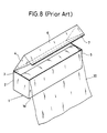
- Fig.8 is a perspective view showing a conventional dispensing carton for a roll film.
- a dispensing carton which is most analogous to the carton of Fig. 8 is disclosed in U.S.Patent No.4,307,828, for example.
- numeral 1 denotes a dispensing carton formed into a rectangular parallelepiped.
- the carton 1 contains a film 30 wound about a core into a roll.
- a lid member 4 which covers an opening 3 of the carton 11 is joined to a rear panel 2 of the carton 1.
- the lid member 4 is formed at an end thereof with a flange 6 which overlaps a front panel 5.
- a metal cutter is mounted to a tip of the flange 6.
- a tip of the cutter 7 is provided with a sawtooth edge which is slightly protruded from the tip of the flange 6 and extend in parallel with a base 1a of the carton.
- the cutting operation of the film in the conventional dispensing carton is now described in detail.
- the rectangular coordinates X, Y and Z are superposed in the dispensing carton as shown in Fig. 9.
- the X-axis is a perpendicular axis to the surfaces of the rear panel 2 and the front panel 5 and the direction extending to the front panel 5 from the rear panel 2 is the positive direction of the X-axis while the direction extending to the rear panel 2 from the front panel 2 is the negative direction of the X-axis.
- the Y-axis is a perpendicular axis to the surfaces of side panels 8 and 9 and the direction extending to the side panel 9 from the side panel 8 is the positive direction of the Y-axis while the direction extending to the side panel 8 from the side panel 9 is the negative direction of the Y-axis.
- the Z-axis is the perpendicular direction to both of the X-and Y-axes and the direction extending to the opening 3 from the base 1a is the positive direction of the Z-axis while the direction extending to the base 1a from the opening 3 is the negative direction of the Z-axis.
- the dispensing carton is first held by the left hand and an end of the film 30 is then held by the right hand to pull out it in the positive direction of the X-axis in the X-Y plane.
- the corner of the film 30 near the position A shown in Fig.9 is held by the right hand and is tensioned with a moderate tension T in the X-axis direction by both hands.
- a portion of the lid member 4 near the portion a shown in Fig.9 is then depressed in the negative direction of the Z-axis by the left hand and the tension T given to the corner of the film near the portion A is slightly increased while the corner is slightly lifted in the positive direction of the Z-axis by the right hand.
- an end of the film 30 is cut by a portion B of the cutter 7 and the film 30 is further cut along the cutter 7 in the negative direction of the Y-axis.
- the cut film is used to wrap foodstuffs put on a tray.
- the above cutting operation possesses the following drawbacks.
- the tray is covered by the film 30 fully opened along the X-Y plane.
- the tension T is slightly increased while the corner of the film is slightly lifted up in the positive direction of the Z-axis by the right hand at the same time that the portion a or its vicinity of the lid member is depressed in the negative direction of the Z-axis, the depressing operation in the negative direction of the Z-axis and the lifting operation of the positive direction of the Z-axis are often overlarge or the increased amount of the tension T is often overlarge.
- the cut film 30 can not be kept opened fully along the X-Y plane and hence the film 30 held by the right hand is wrinkled or intertwined to be hung down so that an area of the film enough to cover the tray can not be obtained.
- a dispensing carton in which a roll film is contained includes a box consisting of a bottom panel, a rear panel, a front panel, both side panels and an opening formed in an upper portion thereof, a lid member which is hingedly joined to an upper end of the rear panel, and a front flange joined to an end of the lid member to overlap the front panel when the lid member is closed.
- a cutter is provided in an end of the front flange and an intermediate portion of the cutter is protruded toward a base of the box.
- the middle portion of the film is cut by the protruded portion of the cutter and the cutting operation of the film is advanced along the cutter so that the film is smoothly and completely cut into a slightly V-letter shape when the film is further pulled in the horizontal direction as it is.
- the cut film is fully spread horizontally without wrinkle and intertwinement and the spread film can be used to cover a tray or the like.
- a dispensing carton 11 manufactured of paper.
- the carton 11 includes a rear panel 13, a front panel 18, side panels 19a and 19b and a bottom panel 11a, and is formed into a rectangular parallelepiped.
- the carton 11 includes an opening 12 formed in the upper portion thereof.
- a lid member 14 which covers the opening 12 is integrally joined to an upper end of the rear panel 13 of the carton 11.
- a front flange 15 is provided in a front end of the lid member 14 and further a tear strip 17 is formed in an end of the front flange 15 with a line of perforation 16 being formed between the front flange 15 and the tear strip 17.
- Both sides of the lid member 14 is formed with side flanges 20a and 20b.
- the rear side of the tear strip 17 is joined to the front side of the front panel 18 at several spots with paste 19.
- the carton 11 contains a film 30 wound on a core 22 into a roll.
- the film is made from, for example, synthetic resin such as vinylidene chloride copolymers, poly-vinyl chloride or poly-butadiene.
- a metal cutter 21 is mounted to a rear side of the end of the front flange 15.
- a tip of the cutter 21 is formed with a sawtooth edge 21a which is protruded from the end of the front flange 15 and is positioned behind the tear strip 17 in the state shown in Figs.1 and 3.
- the center C of the cutter 21 is protruded toward the base 11a of the carton 11. More particularly, as shown in Figs.1 and 2, the center C of the cutter 21 is formed into a sharp point or edge and the sawtooth edges at the both sides of the center are tilted with respect to the base 11a of the carton 11 and extend straight.
- the center of the perforation line 16 constituting the boundary between the front flange 15 and the tear strip 17 is also protruded toward the base correspondingly and the front flange is formed into a substantially triangular shape.
- the front panel 18 includes an upper edge which is bent to the inside of the carton to from a bent portion 18a which is joined to the rear side of the front panel 18 with an adhesive tape 23.
- the front panel 18 is formed with an opening 18b which constitutes film retaining means.
- the adhesive tape 23 is exposed from the film retainer 18b.
- the adhesive tape 23 exposed from the retainer 18b serves to hold leading tip of the remaining film in the front of the front panel 18 when the film pulled out from the carton 11 has been cut by the cutter.
- a U-shaped cut or slit 15a is formed in the front flange 15 and a portion defined by the cut 15a constitutes a depressed piece 15b which can be deformed or bent inside the film retainer 18b as shown by a single-dotted broken line of Fig.5.
- the depressed piece 15b is held or pressed by a finger to cut the film 30 by the cutter 21, the depressed piece 15b is deformed inside and the film 30 pulled out in the front of the front panel 18 is pressed against the adhesive tape 23 in the film retainer 18b so that the film 30 is adhesively held by the adhesive tape 23.
- the rectangular coordinates X, Y and Z are superposed in the dispensing superpose as shown in Figs. 1, 2, 6 and 7.
- the X-axis is a perpendicular axis to the surfaces of the rear panel 13 and the front panel 18 and the direction extending to the front panel 18 from the rear panel 13 is the positive direction of the X-axis while the direction extending to the rear panel 13 from the front panel 18 is the negative direction of the X-axis.
- the Y-axis is a perpendicular axis to the surfaces of the side panels 19a and 19b and the direction extending to the side panel 19b from the side panel 19a is the positive direction of the Y-axis while the direction extending to the side panel 19a from the side panel 19b is the negative direction of the Y-axis.
- the Z-axis is the perpendicular direction to both of the X- and Y-axes and the direction extending to the opening 12 from the base 11a is the positive direction of the Z-axis while the direction extending to the base 11a from the opening 12 is the negative direction of the Z-axis.
- the tear strip 17 joined to the front panel 18 of the carton 11 is stripped off and separated from the front flange 15 along the perforation line 16.
- the sawtooth edge 21a of the cutter 21 is exposed or protruded from the end of the front flange 15 as shown in Fig.2.
- the upper end 13a of the rear panel 13 of the carton 11 serves as a hinge so that the lid member 14 and the front flange 15 can be opened and closed with respect to the opening 12 of the carton 21.
- the film 30 wound on the core 22 is pulled out between the front panel 18 and the front flange 15.
- the dispensing carton is held by the left hand and the front flange 15 is held or pressed by the thumb, for example, as shown in Fig.6.
- the lid member 14 may be held by the thumb.
- the film 30 is held at the central tip thereof by the right hand.
- the sawtooth edge 21a of the cutter 21 protruded from the end of the front flange 15 includes the center C formed into the protruded edge, and accordingly when the central tip of the film 30 is pulled out in the positive direction of the X-axis by the right hand, the middle portion of the film 30 is cut by the center C of the sawtooth edge 21a.
- the cut operation of the film is advanced in the direction toward both sides of the film along the sawtooth edge 21a so that the film 30 is cut smoothly and completely into the slightly V-letter shape.
- the film 30 can be cut only by pulling the film in the positive direction of the X-axis with respect to the carton, any wrinkle is not formed in the cut film 30 or the film is not joined to each other with intertwinement. Accordingly, if the cut film 30 held by the right hand is lowered to an object to be wrapped such as foodstuffs and a tray as it is, the cut film 30 which has been spread substantially horizontally (in the X-Y plane) with a sufficient area is put on the object such as the tray.
- the film 30 when the film 30 is cut in the state of Fig.6 while the pressed piece 15b formed in the front flange 15 is held or pressed by the thumb of the left hand, the film 30 positioned behind the pressed piece 15b can be pressed within the film retainer 18b formed in the front panel 18 through the pressed piece 15b. Accordingly, the film 30 remaining between the front flange 15 and the front panel 18 after the film has been completely cut is held by the adhesive tape 23 in the film retainer 18b. Thus, it can be prevented that the film 30 is rewound into the carton 11 after the film has been cut to wrap the foodstuffs and the tray.
- Fig.7 shows another embodiment, in which the front flange 15 and the cutter mounted thereto include a center which is protruded into a substantially trapezoid shape.
- the cutting operation of the film 30 is performed in the same manner as shown in Fig.6. Namely, a middle portion of the film 30 is cut by the sawtooth edge 21a positioned in the protruded portion J in the form of trapezoid and the film is smoothly and completely cut only by pulling the central end of the film in the positive direction of the X-axis.
- the front panel 18 of the carton 11 is formed with a substantially arcuated cut or slit 18c. After the film has been cut by a desired length, the protruded portion J can be inserted into the cut 18c. Accordingly, when the dispensing carton is not used, the lid member 14 can be prevented from being opened.
- the cutter 21 may be formed into the substantially triangular or trapezoid shape, the cutter 21 may be formed into an arcuated shape and the central portion thereof may be protruded toward the base 11a of the carton 11.
- the middle portion of the film is first cut by the protruded edge only by pulling the film in the positive direction of the X-axis without lifting the film pulled out from the carton in the X-Y plane in the positive direction of the Z-axis, and then the cut operation of the film is advanced in the direction toward both sides of the film along the sawtooth edge so that the film is cut smoothly and completely into the slightly V-letter shape.
- any wrinkle is not formed in the cut film and the cut film is not joined to each other with intertwinement. It is not necessary to spread the cut film in the X-Y plane by both hands and the cut film can be used to wrap the object such as the tray as it is.
Landscapes
- Engineering & Computer Science (AREA)
- Mechanical Engineering (AREA)
- Cartons (AREA)
Abstract
Description
- The present invention relates to a dispensing carton which contains a roll film used to wrap foodstuffs and can cut the film to dispense it.
- More particularly, the present invention concerns a dispensing carton for a roll film which can cut the film by a cutter exactly only by pulling the film from the carton in the horizontal direction with respect to the carton.
- Film used to wrap foodstuffs together with a tray on which the foodstuffs are put is wound into a roll and contained in a carton. A lid member of the carton includes a front flange connected continuously thereto and which is provided with a cutter. The film pulled from the carton is cut by the cutter to a desired length.
- Fig.8 is a perspective view showing a conventional dispensing carton for a roll film. A dispensing carton which is most analogous to the carton of Fig. 8 is disclosed in U.S.Patent No.4,307,828, for example.
- In Fig.8, numeral 1 denotes a dispensing carton formed into a rectangular parallelepiped. The carton 1 contains a
film 30 wound about a core into a roll. A lid member 4 which covers anopening 3 of thecarton 11 is joined to arear panel 2 of the carton 1. The lid member 4 is formed at an end thereof with aflange 6 which overlaps afront panel 5. A metal cutter is mounted to a tip of theflange 6. A tip of thecutter 7 is provided with a sawtooth edge which is slightly protruded from the tip of theflange 6 and extend in parallel with abase 1a of the carton. - The cutting operation of the film in the conventional dispensing carton is now described in detail. For convenience of the description, the rectangular coordinates X, Y and Z are superposed in the dispensing carton as shown in Fig. 9. The X-axis is a perpendicular axis to the surfaces of the
rear panel 2 and thefront panel 5 and the direction extending to thefront panel 5 from therear panel 2 is the positive direction of the X-axis while the direction extending to therear panel 2 from thefront panel 2 is the negative direction of the X-axis. The Y-axis is a perpendicular axis to the surfaces ofside panels 8 and 9 and the direction extending to the side panel 9 from theside panel 8 is the positive direction of the Y-axis while the direction extending to theside panel 8 from the side panel 9 is the negative direction of the Y-axis. The Z-axis is the perpendicular direction to both of the X-and Y-axes and the direction extending to theopening 3 from thebase 1a is the positive direction of the Z-axis while the direction extending to thebase 1a from theopening 3 is the negative direction of the Z-axis. - The cutting operation in the conventional dispensing carton is described using the X, Y and Z axes defined above.
- The dispensing carton is first held by the left hand and an end of the
film 30 is then held by the right hand to pull out it in the positive direction of the X-axis in the X-Y plane. After the end of the film has been pulled out by a desired length as shown in Fig.9, the corner of thefilm 30 near the position A shown in Fig.9 is held by the right hand and is tensioned with a moderate tension T in the X-axis direction by both hands. A portion of the lid member 4 near the portion a shown in Fig.9 is then depressed in the negative direction of the Z-axis by the left hand and the tension T given to the corner of the film near the portion A is slightly increased while the corner is slightly lifted in the positive direction of the Z-axis by the right hand. Consequently, an end of thefilm 30 is cut by a portion B of thecutter 7 and thefilm 30 is further cut along thecutter 7 in the negative direction of the Y-axis. The cut film is used to wrap foodstuffs put on a tray. However, the above cutting operation possesses the following drawbacks. - It is desirable that the tray is covered by the
film 30 fully opened along the X-Y plane. However, actually, when the tension T is slightly increased while the corner of the film is slightly lifted up in the positive direction of the Z-axis by the right hand at the same time that the portion a or its vicinity of the lid member is depressed in the negative direction of the Z-axis, the depressing operation in the negative direction of the Z-axis and the lifting operation of the positive direction of the Z-axis are often overlarge or the increased amount of the tension T is often overlarge. In such a case, thecut film 30 can not be kept opened fully along the X-Y plane and hence thefilm 30 held by the right hand is wrinkled or intertwined to be hung down so that an area of the film enough to cover the tray can not be obtained. - It is an object of the present invention to provide a dispensing carton in which a film pulled out therefrom can be cut smoothly and completely without wrinkle and intertwinement only by pulling out the film from the carton in the horizontal (X-axis) direction without lifting the pulled film in the positive direction of the Z-axis extremely.
- It is another object of the present invention to provide a dispensing carton in which a film can be cut while fully spread horizontally and a tray is covered by the cut film fully spread without wrinkle and intertwinement.
- According to the present invention, a dispensing carton in which a roll film is contained includes a box consisting of a bottom panel, a rear panel, a front panel, both side panels and an opening formed in an upper portion thereof, a lid member which is hingedly joined to an upper end of the rear panel, and a front flange joined to an end of the lid member to overlap the front panel when the lid member is closed. A cutter is provided in an end of the front flange and an intermediate portion of the cutter is protruded toward a base of the box. When the film pulled out from the box is led between the front flange and the front panel and is further pulled in the horizontal direction with the lid member being closed, the middle portion of the film is cut by the protruded portion of the cutter and the cutting operation of the film is advanced along the cutter so that the film is smoothly and completely cut into a slightly V-letter shape when the film is further pulled in the horizontal direction as it is. Thus, the cut film is fully spread horizontally without wrinkle and intertwinement and the spread film can be used to cover a tray or the like.
-
- Fig.1 is a perspective view of a dispensing carton, not opened, for a roll film according to the present invention;
- Fig.2 is a perspective view of a dispensing carton, which has been opened, for a roll film according to the present invention;
- Fig.3 is a sectional view showing a dispensing carton which has not been opened;
- Fig.4 is a sectional view showing a dispensing carton which has been opened and includes a lid member which is closed;
- Fig.5 is an enlarged sectional view of a film retainer provided in a front panel of the dispensing carton;
- Fig.6 is a perspective view showing the dispensing carton from which a film is pulled out to be cut;
- Fig. 7 is a perspective view showing another structure of a dispensing carton for a roll film according to the present invention;
- Fig.8 is a perspective view showing a conventional dispensing carton for a roll film; and
- Fig.9 is a perspective view showing a conventional dispensing carton for a roll film in which the film is to be cut.
- Referring to Figs. 1 and 2, there is shown a dispensing
carton 11 manufactured of paper. Thecarton 11 includes arear panel 13, afront panel 18,side panels bottom panel 11a, and is formed into a rectangular parallelepiped. Thecarton 11 includes anopening 12 formed in the upper portion thereof. Alid member 14 which covers theopening 12 is integrally joined to an upper end of therear panel 13 of thecarton 11. Afront flange 15 is provided in a front end of thelid member 14 and further atear strip 17 is formed in an end of thefront flange 15 with a line ofperforation 16 being formed between thefront flange 15 and thetear strip 17. Both sides of thelid member 14 is formed withside flanges tear strip 17 is joined to the front side of thefront panel 18 at several spots withpaste 19. - The
carton 11 contains afilm 30 wound on acore 22 into a roll. The film is made from, for example, synthetic resin such as vinylidene chloride copolymers, poly-vinyl chloride or poly-butadiene. - A
metal cutter 21 is mounted to a rear side of the end of thefront flange 15. A tip of thecutter 21 is formed with asawtooth edge 21a which is protruded from the end of thefront flange 15 and is positioned behind thetear strip 17 in the state shown in Figs.1 and 3. The center C of thecutter 21 is protruded toward thebase 11a of thecarton 11. More particularly, as shown in Figs.1 and 2, the center C of thecutter 21 is formed into a sharp point or edge and the sawtooth edges at the both sides of the center are tilted with respect to thebase 11a of thecarton 11 and extend straight. The center of theperforation line 16 constituting the boundary between thefront flange 15 and thetear strip 17 is also protruded toward the base correspondingly and the front flange is formed into a substantially triangular shape. - As shown in Fig.5 on the enlarged scale, the
front panel 18 includes an upper edge which is bent to the inside of the carton to from abent portion 18a which is joined to the rear side of thefront panel 18 with anadhesive tape 23. As shown in Fig.2, thefront panel 18 is formed with an opening 18b which constitutes film retaining means. Theadhesive tape 23 is exposed from thefilm retainer 18b. Theadhesive tape 23 exposed from theretainer 18b serves to hold leading tip of the remaining film in the front of thefront panel 18 when the film pulled out from thecarton 11 has been cut by the cutter. A U-shaped cut or slit 15a is formed in thefront flange 15 and a portion defined by thecut 15a constitutes adepressed piece 15b which can be deformed or bent inside thefilm retainer 18b as shown by a single-dotted broken line of Fig.5. When thedepressed piece 15b is held or pressed by a finger to cut thefilm 30 by thecutter 21, thedepressed piece 15b is deformed inside and thefilm 30 pulled out in the front of thefront panel 18 is pressed against theadhesive tape 23 in thefilm retainer 18b so that thefilm 30 is adhesively held by theadhesive tape 23. - For convenience of the description of the usage of the dispensing carton, the rectangular coordinates X, Y and Z are superposed in the dispensing superpose as shown in Figs. 1, 2, 6 and 7. The X-axis is a perpendicular axis to the surfaces of the
rear panel 13 and thefront panel 18 and the direction extending to thefront panel 18 from therear panel 13 is the positive direction of the X-axis while the direction extending to therear panel 13 from thefront panel 18 is the negative direction of the X-axis. The Y-axis is a perpendicular axis to the surfaces of theside panels side panel 19b from theside panel 19a is the positive direction of the Y-axis while the direction extending to theside panel 19a from theside panel 19b is the negative direction of the Y-axis. The Z-axis is the perpendicular direction to both of the X- and Y-axes and the direction extending to theopening 12 from thebase 11a is the positive direction of the Z-axis while the direction extending to thebase 11a from theopening 12 is the negative direction of the Z-axis. - The usage of the dispensing carton according to the embodiment is now described using the X, Y and Z axes defined above.
- When the carton is opened, the
tear strip 17 joined to thefront panel 18 of thecarton 11 is stripped off and separated from thefront flange 15 along theperforation line 16. When thetear strip 17 has been removed, thesawtooth edge 21a of thecutter 21 is exposed or protruded from the end of thefront flange 15 as shown in Fig.2. After the removal of thetear strip 17, theupper end 13a of therear panel 13 of thecarton 11 serves as a hinge so that thelid member 14 and thefront flange 15 can be opened and closed with respect to theopening 12 of thecarton 21. - After the carton has been opened, the
film 30 wound on thecore 22 is pulled out between thefront panel 18 and thefront flange 15. After thefilm 30 has been pulled out by a desired length, the dispensing carton is held by the left hand and thefront flange 15 is held or pressed by the thumb, for example, as shown in Fig.6. Alternatively, thelid member 14 may be held by the thumb. Further, thefilm 30 is held at the central tip thereof by the right hand. Thesawtooth edge 21a of thecutter 21 protruded from the end of thefront flange 15 includes the center C formed into the protruded edge, and accordingly when the central tip of thefilm 30 is pulled out in the positive direction of the X-axis by the right hand, the middle portion of thefilm 30 is cut by the center C of thesawtooth edge 21a. When thefilm 30 is further pulled out in the positive direction of the X-axis as it is, the cut operation of the film is advanced in the direction toward both sides of the film along thesawtooth edge 21a so that thefilm 30 is cut smoothly and completely into the slightly V-letter shape. Thus, since thefilm 30 can be cut only by pulling the film in the positive direction of the X-axis with respect to the carton, any wrinkle is not formed in thecut film 30 or the film is not joined to each other with intertwinement. Accordingly, if thecut film 30 held by the right hand is lowered to an object to be wrapped such as foodstuffs and a tray as it is, thecut film 30 which has been spread substantially horizontally (in the X-Y plane) with a sufficient area is put on the object such as the tray. - The foregoing is the usage of the dispensing carton according to the present invention.
- Furthermore, when the
film 30 is cut in the state of Fig.6 while the pressedpiece 15b formed in thefront flange 15 is held or pressed by the thumb of the left hand, thefilm 30 positioned behind the pressedpiece 15b can be pressed within thefilm retainer 18b formed in thefront panel 18 through the pressedpiece 15b. Accordingly, thefilm 30 remaining between thefront flange 15 and thefront panel 18 after the film has been completely cut is held by theadhesive tape 23 in thefilm retainer 18b. Thus, it can be prevented that thefilm 30 is rewound into thecarton 11 after the film has been cut to wrap the foodstuffs and the tray. - Fig.7 shows another embodiment, in which the
front flange 15 and the cutter mounted thereto include a center which is protruded into a substantially trapezoid shape. In this case, the cutting operation of thefilm 30 is performed in the same manner as shown in Fig.6. Namely, a middle portion of thefilm 30 is cut by thesawtooth edge 21a positioned in the protruded portion J in the form of trapezoid and the film is smoothly and completely cut only by pulling the central end of the film in the positive direction of the X-axis. Further, thefront panel 18 of thecarton 11 is formed with a substantially arcuated cut or slit 18c. After the film has been cut by a desired length, the protruded portion J can be inserted into thecut 18c. Accordingly, when the dispensing carton is not used, thelid member 14 can be prevented from being opened. - In the embodiments, while the
cutter 21 is formed into the substantially triangular or trapezoid shape, thecutter 21 may be formed into an arcuated shape and the central portion thereof may be protruded toward thebase 11a of thecarton 11. - It is not always necessary to provide the protruding central edge C shown in Fig.2 or the protrusion J shown in Fig.7 in the center of the
cutter 21 and it may be provided in any eccentric position in the longitudinal direction of the carton. - As described above, according to the present invention, since the cutting edge provided in the end of the front flange is protruded, the middle portion of the film is first cut by the protruded edge only by pulling the film in the positive direction of the X-axis without lifting the film pulled out from the carton in the X-Y plane in the positive direction of the Z-axis, and then the cut operation of the film is advanced in the direction toward both sides of the film along the sawtooth edge so that the film is cut smoothly and completely into the slightly V-letter shape.
- Accordingly, any wrinkle is not formed in the cut film and the cut film is not joined to each other with intertwinement. It is not necessary to spread the cut film in the X-Y plane by both hands and the cut film can be used to wrap the object such as the tray as it is.
Claims (8)
Applications Claiming Priority (2)
| Application Number | Priority Date | Filing Date | Title |
|---|---|---|---|
| JP60179/87 | 1987-04-20 | ||
| JP6017987 | 1987-04-20 |
Publications (3)
| Publication Number | Publication Date |
|---|---|
| EP0287902A2 true EP0287902A2 (en) | 1988-10-26 |
| EP0287902A3 EP0287902A3 (en) | 1989-11-15 |
| EP0287902B1 EP0287902B1 (en) | 1992-03-04 |
Family
ID=13134671
Family Applications (1)
| Application Number | Title | Priority Date | Filing Date |
|---|---|---|---|
| EP19880105544 Expired - Lifetime EP0287902B1 (en) | 1987-04-20 | 1988-04-07 | Dispensing carton for a roll film |
Country Status (3)
| Country | Link |
|---|---|
| US (1) | US4899918A (en) |
| EP (1) | EP0287902B1 (en) |
| AU (1) | AU582708B2 (en) |
Cited By (2)
| Publication number | Priority date | Publication date | Assignee | Title |
|---|---|---|---|---|
| DE29615121U1 (en) * | 1996-08-30 | 1996-11-14 | Classen-Papertronics KG, 45219 Essen | Packaging container for a PC printer printing paper roll |
| AU2009202941B2 (en) * | 2008-07-25 | 2015-01-22 | Multix Pty Ltd | Film dispenser |
Families Citing this family (13)
| Publication number | Priority date | Publication date | Assignee | Title |
|---|---|---|---|---|
| JPH0245349A (en) * | 1988-07-25 | 1990-02-15 | Kureha Chem Ind Co Ltd | Containing case for wrap film |
| US5031813A (en) * | 1990-06-01 | 1991-07-16 | Dow Brands, Inc. | Dispensing container having a tear strip with end tabs |
| US6682808B2 (en) * | 2001-04-20 | 2004-01-27 | Asahi Kasei Kabushiki Kaisha | Crosslinked laminated wrap film and dispenser box therefor |
| US20030164392A1 (en) * | 2002-03-01 | 2003-09-04 | Gerulski Kristopher W. | Wrap dispenser with enhanced cutter bar registration |
| US20050035133A1 (en) * | 2003-05-29 | 2005-02-17 | Gerulski Kristopher W. | Method and apparatus for dispensing a sheet materials |
| US20050005755A1 (en) * | 2003-05-29 | 2005-01-13 | Turvey Robert R. | Method and apparatus for cutting a sheet material |
| SG11201400231VA (en) * | 2011-09-14 | 2014-08-28 | Asahi Kasei Chemicals Corp | Lid cover for rolled cylinder storage box and rolled cylinder storage device |
| JP2014019483A (en) * | 2012-07-20 | 2014-02-03 | Kureha Corp | Wound body storage box and wound body-contained storage box |
| JP6346520B2 (en) * | 2014-07-30 | 2018-06-20 | 東洋アルミエコープロダクツ株式会社 | Roll sheet storage box |
| JP6541975B2 (en) * | 2014-08-07 | 2019-07-10 | 株式会社クレハ | Rolled-in container box and wound-in container |
| JP7096064B2 (en) * | 2018-05-11 | 2022-07-05 | 株式会社クレハ | Cutting blades and packaging containers |
| JP2021031082A (en) * | 2019-08-21 | 2021-03-01 | 旭化成株式会社 | How to use the winding body storage box, storage device and winding body storage box |
| US11760558B2 (en) | 2021-02-15 | 2023-09-19 | Richard F. Jones | Dispenser carton blank and assembly |
Family Cites Families (13)
| Publication number | Priority date | Publication date | Assignee | Title |
|---|---|---|---|---|
| US2771186A (en) * | 1952-10-24 | 1956-11-20 | Sutherland Paper Co | Dispensing carton, cutter and method of making |
| US3096918A (en) * | 1961-09-01 | 1963-07-09 | Container Corp | Dispensing carton with concealed cutting blade |
| US3542268A (en) * | 1968-05-31 | 1970-11-24 | Speed Equipment Inc | Film dispenser with serrated piercing blade |
| AU1309470A (en) * | 1970-03-25 | 1971-09-30 | W. C. Penfold & Co. Pty. Limited | Dispenser carton |
| US3933288A (en) * | 1974-11-15 | 1976-01-20 | Diamond International Corporation | Dispensing carton with cutting edge |
| US4307828A (en) * | 1980-06-19 | 1981-12-29 | The Dow Chemical Company | Dispensing carton |
| US4426029A (en) * | 1981-12-30 | 1984-01-17 | Union Carbide Corporation | Safety blade for severing stretchable film |
| US4458570A (en) * | 1982-01-25 | 1984-07-10 | Marvin Glass & Associates | Sheet material dispenser |
| NO152163C (en) * | 1983-03-02 | 1985-08-14 | Tomra Systems As | CUTTING DEVICE FOR A CONTINUOUS PAPER COAT |
| US4549689A (en) * | 1983-08-12 | 1985-10-29 | Champion International Corporation | Carton for dispensing rolled sheet material |
| US4646956A (en) * | 1984-07-20 | 1987-03-03 | Clik-Cut, Inc. | Sheet material dispenser |
| US4586639A (en) * | 1984-07-20 | 1986-05-06 | Clik-Cut, Inc. | Sheet material dispenser and method of dispensing sheet material |
| US4648537A (en) * | 1985-09-23 | 1987-03-10 | The Dow Chemical Company | Dispenser carton with dual interdigitating cutting edges |
-
1988
- 1988-04-06 US US07/178,127 patent/US4899918A/en not_active Expired - Lifetime
- 1988-04-07 EP EP19880105544 patent/EP0287902B1/en not_active Expired - Lifetime
- 1988-04-19 AU AU14765/88A patent/AU582708B2/en not_active Expired
Cited By (2)
| Publication number | Priority date | Publication date | Assignee | Title |
|---|---|---|---|---|
| DE29615121U1 (en) * | 1996-08-30 | 1996-11-14 | Classen-Papertronics KG, 45219 Essen | Packaging container for a PC printer printing paper roll |
| AU2009202941B2 (en) * | 2008-07-25 | 2015-01-22 | Multix Pty Ltd | Film dispenser |
Also Published As
| Publication number | Publication date |
|---|---|
| EP0287902B1 (en) | 1992-03-04 |
| EP0287902A3 (en) | 1989-11-15 |
| AU582708B2 (en) | 1989-04-06 |
| US4899918A (en) | 1990-02-13 |
| AU1476588A (en) | 1988-10-20 |
Similar Documents
| Publication | Publication Date | Title |
|---|---|---|
| EP0352634B1 (en) | Dispensing carton for a roll film | |
| EP0287902B1 (en) | Dispensing carton for a roll film | |
| EP1075436B1 (en) | A tissue box | |
| US6716150B2 (en) | Easy open envelope | |
| JP3291052B2 (en) | Paper handkerchief storage pack and its blank | |
| US5190199A (en) | Dispensing carton with cutting means protector | |
| US4474318A (en) | Dispenser carton | |
| KR20000064453A (en) | Corrugated box for pack of commercial products | |
| US4958733A (en) | Container for accommodating string-like articles and taking out the same | |
| JPH04239444A (en) | Dispenser container with tear strip equipped with terminal tab | |
| JP2001031104A (en) | Wrap carton | |
| JPH0419092B2 (en) | ||
| JPH0734823Y2 (en) | Wrap film storage case | |
| JP3381552B2 (en) | Box for tissue paper and folding method thereof | |
| JP3237875B2 (en) | Carton for wrap film | |
| JP3197319B2 (en) | Carton for wrap film | |
| JP2556431B2 (en) | Wrap film storage case | |
| JP2542998B2 (en) | Wrap film storage case | |
| JP2628257B2 (en) | Sheet distribution case | |
| JPH0619512Y2 (en) | Sanitary paper in storage box | |
| JP2505721B2 (en) | Wrap film storage case | |
| JP2505722B2 (en) | Wrap film packaging method | |
| JPH074186Y2 (en) | Seat roll storage case | |
| JPH1077047A (en) | Container box for rolled film | |
| JPH10287327A (en) | Web storage carton for packaging |
Legal Events
| Date | Code | Title | Description |
|---|---|---|---|
| PUAI | Public reference made under article 153(3) epc to a published international application that has entered the european phase |
Free format text: ORIGINAL CODE: 0009012 |
|
| AK | Designated contracting states |
Kind code of ref document: A2 Designated state(s): DE FR GB NL |
|
| PUAL | Search report despatched |
Free format text: ORIGINAL CODE: 0009013 |
|
| AK | Designated contracting states |
Kind code of ref document: A3 Designated state(s): DE FR GB NL |
|
| 17P | Request for examination filed |
Effective date: 19891212 |
|
| 17Q | First examination report despatched |
Effective date: 19910111 |
|
| GRAA | (expected) grant |
Free format text: ORIGINAL CODE: 0009210 |
|
| AK | Designated contracting states |
Kind code of ref document: B1 Designated state(s): DE FR GB NL |
|
| REF | Corresponds to: |
Ref document number: 3868672 Country of ref document: DE Date of ref document: 19920409 |
|
| ET | Fr: translation filed | ||
| PLBE | No opposition filed within time limit |
Free format text: ORIGINAL CODE: 0009261 |
|
| STAA | Information on the status of an ep patent application or granted ep patent |
Free format text: STATUS: NO OPPOSITION FILED WITHIN TIME LIMIT |
|
| 26N | No opposition filed | ||
| PGFP | Annual fee paid to national office [announced via postgrant information from national office to epo] |
Ref country code: GB Payment date: 19970401 Year of fee payment: 10 |
|
| PGFP | Annual fee paid to national office [announced via postgrant information from national office to epo] |
Ref country code: FR Payment date: 19970409 Year of fee payment: 10 |
|
| PGFP | Annual fee paid to national office [announced via postgrant information from national office to epo] |
Ref country code: DE Payment date: 19970414 Year of fee payment: 10 |
|
| PGFP | Annual fee paid to national office [announced via postgrant information from national office to epo] |
Ref country code: NL Payment date: 19970428 Year of fee payment: 10 |
|
| PG25 | Lapsed in a contracting state [announced via postgrant information from national office to epo] |
Ref country code: GB Free format text: LAPSE BECAUSE OF NON-PAYMENT OF DUE FEES Effective date: 19980407 |
|
| PG25 | Lapsed in a contracting state [announced via postgrant information from national office to epo] |
Ref country code: FR Free format text: THE PATENT HAS BEEN ANNULLED BY A DECISION OF A NATIONAL AUTHORITY Effective date: 19980430 |
|
| PG25 | Lapsed in a contracting state [announced via postgrant information from national office to epo] |
Ref country code: NL Free format text: LAPSE BECAUSE OF NON-PAYMENT OF DUE FEES Effective date: 19981101 |
|
| GBPC | Gb: european patent ceased through non-payment of renewal fee |
Effective date: 19980407 |
|
| NLV4 | Nl: lapsed or anulled due to non-payment of the annual fee |
Effective date: 19981101 |
|
| PG25 | Lapsed in a contracting state [announced via postgrant information from national office to epo] |
Ref country code: DE Free format text: LAPSE BECAUSE OF NON-PAYMENT OF DUE FEES Effective date: 19990202 |
|
| REG | Reference to a national code |
Ref country code: FR Ref legal event code: ST |