EP0287905A1 - Procédé pour désactiver une étiquette résonante et circuit de mise en oeuvre du procédé - Google Patents
Procédé pour désactiver une étiquette résonante et circuit de mise en oeuvre du procédé Download PDFInfo
- Publication number
- EP0287905A1 EP0287905A1 EP88105582A EP88105582A EP0287905A1 EP 0287905 A1 EP0287905 A1 EP 0287905A1 EP 88105582 A EP88105582 A EP 88105582A EP 88105582 A EP88105582 A EP 88105582A EP 0287905 A1 EP0287905 A1 EP 0287905A1
- Authority
- EP
- European Patent Office
- Prior art keywords
- pulse
- circuit
- discharge
- resonance
- receiving
- Prior art date
- Legal status (The legal status is an assumption and is not a legal conclusion. Google has not performed a legal analysis and makes no representation as to the accuracy of the status listed.)
- Granted
Links
Images
Classifications
-
- G—PHYSICS
- G08—SIGNALLING
- G08B—SIGNALLING SYSTEMS, e.g. PERSONAL CALLING SYSTEMS; ORDER TELEGRAPHS; ALARM SYSTEMS
- G08B13/00—Burglar, theft or intruder alarms
- G08B13/22—Electrical actuation
- G08B13/24—Electrical actuation by interference with electromagnetic field distribution
- G08B13/2402—Electronic Article Surveillance [EAS], i.e. systems using tags for detecting removal of a tagged item from a secure area, e.g. tags for detecting shoplifting
- G08B13/2405—Electronic Article Surveillance [EAS], i.e. systems using tags for detecting removal of a tagged item from a secure area, e.g. tags for detecting shoplifting characterised by the tag technology used
- G08B13/2414—Electronic Article Surveillance [EAS], i.e. systems using tags for detecting removal of a tagged item from a secure area, e.g. tags for detecting shoplifting characterised by the tag technology used using inductive tags
- G08B13/242—Tag deactivation
Definitions
- the invention relates to a method according to the preamble of claim 1 and to a circuit arrangement for performing the method.
- resonance labels are attached to the goods to protect them against theft, which must be deactivated when paying at the cash desk, but possibly also after showing the cash receipt confirmation when the goods are picked up at the packing table. If a label is not deactivated, this can be recognized by a monitoring system arranged in the exit area, which stimulates the labels to resonate and detects a label that has not been deactivated on the resonance.
- the deactivation takes place conventionally by excitation of the label with about ten times the power, which leads to the burning of the resonant circuit or its capacitor.
- the high current surge can also trigger an alarm at the exit of the department store, especially if the cash register is located close enough. This risk can only be eliminated by expensive circuitry measures.
- Another difficulty is that such a high performance of a broadcaster (and this is what it is here for) requires the approval of the postal authority and it is difficult (or not at all) to obtain it.
- this means that the monitoring device is ultimately switched off more than switched on, so that under certain circumstances a thief with stolen goods can still slip through.
- the invention is based on the object of designing a method of the type mentioned at the outset and an associated circuit arrangement in such a way that the resonance labels can be checked or deactivated without interference.
- a first step towards solving this task is the realization that the resonance frequency does not need to be released to deactivate the label, but that, with the appropriate strength, a single click pulse is sufficient to excite the resonant circuit of the label to self-destruct.
- the term "cracking disorder" is common in a telephone line; a single pulse from such an interference signal is therefore a click pulse.
- the procedure according to claim 3 can be followed, the label then being deactivated by a further pulse if this should not be the case with the first pulse.
- it can also be carried out according to claim 4, it being preferred to combine the two procedures by emitting at least one second discharge pulse, which may then also be used for checking.
- a circuit arrangement for carrying out the method according to the invention is characterized by the features of claim 5.
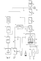
- a goods provided with a resonance label E are either brought to the cash register or are collected from a packing table after payment at the cash register.
- the resonance label E must be deactivated, which is initiated by actuating a switching element.
- This switching element can simply be manually, e.g. by the cashier to be operated, but is preferably formed by a sensor LDR, which automatically detects the passage of the goods and activates the deactivation circuit.
- the sensor LDR is formed by a light barrier or a light reflector with a photoelectric converter LDR, but various configurations are possible, for example a piezosensor that detects the weight of the goods on a base or a circle that simulates the inspection circuit at the department store exit, the one Sends out resonance vibration and uses the "echo" of the label E to determine its presence.
- An amplifier 1 is connected downstream of the sensor LDR, in particular one with a large gain, such as a threshold switch, which converts the voltage change at the output of the sensor LDR into a voltage step. From this step signal, a timing element 2, in particular a monoflop, is triggered, possibly via a coupling capacitor which supplies a needle pulse, which keeps a downstream OR gate 3 open for a predetermined time.
- a pulse generator 4 is switched on via the OR gate 3 switches, which emits at least two, preferably more, pulses with interposed pulse pauses.
- the pulse pause times are preferably a multiple of the pulse times.
- the pulse sequence delivered in this way serves a dual purpose, namely on the one hand to ensure the destruction of the resonance tag E (if this is not already possible with the first pulse) and on the other hand to check the success of the destruction. Since the lowest possible energy is used, the destruction can fail if the label E is placed on a very large piece of goods at a location distant from the transmitting antenna L1, for example on the underside.
- a voltage converter 6 charges a capacitor C1 via a resistor R1.
- a resistor is referred to here, then it is understood to mean any circuit which results in a current resistor.
- transistors can also be operated as variable resistors.
- the capacitor C1 is connected to ground via a controllable switch 5, the switch 5 being closed by the pulses from the pulse generator 5. It is therefore understood that the pulse pause times are to be dimensioned such that the capacitor C1 can be recharged by the voltage converter 6 during this time.
- the timer 2 operates here to a certain extent as a gate circuit for determining the Number of pulses to be output by the pulse generator 4. It would therefore be readily possible to place a gate circuit at the output of a free-running pulse generator 4 and to pass pulses only during a predetermined time. It would also be conceivable to design the pulse generator 4 as a start-stop generator instead of the timing element 2, said generator generating a predetermined number of pulses after being triggered by the pulse from the amplifier 1.
- the ratio of pulse to pause time can advantageously be of the order of 1: 10000.
- the pulse pause times between the pulses of the pulse generator 4 will be discussed again. Normally, the pause times on such a generator are always the same, and the pulses occur periodically. However, this means that the pulses are emitted at a predetermined frequency. This can be a disadvantage for the present purposes if interference is to be expected from such a frequency. It is therefore expedient to make the pulse pause times uneven by switching the pulse generator 4 accordingly. This can either be done in such a way that they are determined by a connected or integrated random generator, or - as is preferred - that they are changed according to a predetermined law, i.e. either lengthened or shortened after each pulse, the extent of this change remaining constant or can be variable.
- the receiving and test antenna L2 can be arranged together with the transmitting antenna L1.
- the transmitting antenna L1 at the cash register and the test antenna L2 at the packing table can also be provided.
- a procedure can also be adopted, as is known from radar and echo sounder technology, in that one and the same antenna is used by switching once as a transmitting antenna and then again as a receiving antenna.
- this is generally not preferred for the present purposes, as will be explained below.
- the relatively strong discharge pulse of capacitor C1 will generally require limiting measures to protect the receiving circuit.
- the number of turns times the area product should be of the same size, but connected in series with the opposite polarity, so that the voltage induced by the excitation coil L1 is compensated to a first approximation.
- the coil L1 when assembling the antenna coils L1, L2, it would be possible to design the coil L1 as a rectangle, in which the receiving coil L2 (as shown) is installed as a symmetrical "8".
- this limiting circuit contains a limiting transformer T, which is preferably designed as a symmetrical ferrite transformer, in particular a relatively small magnetic cross section. This measure alone leads to a first safe limitation and thus to protection of the downstream receiving circuit, because in addition to any down-transformation, the saturation of the ferrite core (which is relatively small in relation to the signal) constitutes a further limitation of the signal emitted.
- a center tap is provided on the secondary side of the transformer T, which is connected to ground.
- An alternative or additional measure can consist in the arrangement (provided on the output side of the ferrite transformer T) of a diode circuit D with diodes connected in parallel with the anit. Silicon diodes or a low junction capacitance are preferred. It would also be possible to use Schottky diodes, which are correspondingly fast, but they are more expensive than the silicon diodes mentioned.
- the circuit 7 has an amplifier A, which is expediently designed as a, in particular fully symmetrical, push-pull amplifier. This is also a protective measure by which common-mode interference signals, in particular capacitively transmitted to the receiving antenna L2, are effectively suppressed. At the same time, the cross-modulation products that occur in the event of overmodulation are reduced.
- a simple measure to circumvent this difficulty is that a timer 8 is in the receiving circuit, which switch 8 only closes the receiving circuit a predetermined time after the discharge pulse has been emitted via the antenna L1.
- this presupposes that the transmitting and receiving circuit are synchronized with one another, ie that the switch 8 is controlled by the transmitting circuit.
- the control input of the switch 8 connected to the switching element LDR, 1-5 discharging the capacitor C1.
- the control line 13 could be connected directly to the circuit of the capacitor C1 or to the switch 5, but this is generally not preferred for dimensional reasons. It is more favorable to connect the control line to the output of the pulse generator 4 (or one of the equivalent circuits mentioned above).
- the delay time after the discharge pulse is emitted until the switch 8 closes is determined by a timer integrated in the switch 8, for example a monoflop, but the timer or monoflop can also be provided separately in line 13.
- the delay time is at least 2 ⁇ s, but must not be too long. A range of 5 to 50 ⁇ s should be optimal. Subsequently, the switch 8 should not remain open too long in order to exclude interference signals as far as possible. An open time of 10 ⁇ s to a maximum of 60 ⁇ s, preferably a maximum of 50 ⁇ s, is entirely satisfactory.
- the above-mentioned predetermined passes until the closing of the switch 8 , Time. This time is chosen such that the interference vibrations generated in the system by the excitation pulse from the antenna L1 have decayed to such an extent that a signal originating from a label E which has remained undamaged at any rate can be recorded significantly.
- the switch 8 If the switch 8 is closed and the receiving antenna L2 receives a ringing from an undamaged label E, these oscillations are expedient integrated in an integrator 9. This may also be protection against interference frequencies, because the integrator 9 is preferably followed by a threshold switch 10, so that a few interference vibrations are not sufficient to exceed the switching threshold of the threshold switch 10.
- the switch 10 serves as a comparator with a predetermined value, namely its threshold value, which can be set via an adjusting resistor (not shown).
- integrator 9 and threshold switch 10 form the detection circuit for a resonance tag E that has remained capable of vibration.
- the detection circuit can be constructed in any way, as is known from radio and radar technology.
- At the output of this detection circuit there is a corresponding evaluation circuit, which is designed either as a pure display with an acoustic display device 11 and / or a visual display device 12, so that the cashier is made aware, for example, that the deactivation process must be repeated.
- the evaluation circuit can also have a signal line 14 in the manner also shown for automating the new deactivation process, which feeds a signal to the switching element LDR, 1-5, which discharges the capacitor C1, for a new start-up.
- the switching element LDR, 1-5 can be implemented in very different ways, and accordingly the output line 14 can also trigger a new switching operation at different points.
- the output line 14 can also trigger a new switching operation at different points.
- any other energy source of corresponding strength can be used instead of a capacitor C1.
- the described deactivation test with the receiving circuit L2, 7-12 could also be carried out in a conventional manner, in particular if the test is carried out at a different location, e.g. at the packing table, is made as the deactivation.
- the advantages achieved by the invention such as speed, etc., are lost when working with frequencies that are matched as precisely as possible.
- a further modification possibility is given at the receiving antenna L2, which is practically designed in the manner of a compensation variometer and can accordingly take all forms known for this design.
Landscapes
- Physics & Mathematics (AREA)
- Engineering & Computer Science (AREA)
- Automation & Control Theory (AREA)
- Computer Security & Cryptography (AREA)
- Electromagnetism (AREA)
- General Physics & Mathematics (AREA)
- Burglar Alarm Systems (AREA)
- Radar Systems Or Details Thereof (AREA)
- Labeling Devices (AREA)
Priority Applications (1)
| Application Number | Priority Date | Filing Date | Title |
|---|---|---|---|
| AT88105582T ATE86403T1 (de) | 1987-04-23 | 1988-04-08 | Verfahren zum deaktivieren einer resonanzetikette und schaltungsanordnung zur durchfuehrung des verfahrens. |
Applications Claiming Priority (2)
| Application Number | Priority Date | Filing Date | Title |
|---|---|---|---|
| CH1564/87 | 1987-04-23 | ||
| CH156487 | 1987-04-23 |
Publications (2)
| Publication Number | Publication Date |
|---|---|
| EP0287905A1 true EP0287905A1 (fr) | 1988-10-26 |
| EP0287905B1 EP0287905B1 (fr) | 1993-03-03 |
Family
ID=4213376
Family Applications (1)
| Application Number | Title | Priority Date | Filing Date |
|---|---|---|---|
| EP88105582A Expired - Lifetime EP0287905B1 (fr) | 1987-04-23 | 1988-04-08 | Procédé pour désactiver une étiquette résonante et circuit de mise en oeuvre du procédé |
Country Status (6)
| Country | Link |
|---|---|
| US (1) | US4906974A (fr) |
| EP (1) | EP0287905B1 (fr) |
| JP (1) | JP2575173B2 (fr) |
| AT (1) | ATE86403T1 (fr) |
| DE (1) | DE3878717D1 (fr) |
| ES (1) | ES2039005T3 (fr) |
Cited By (12)
| Publication number | Priority date | Publication date | Assignee | Title |
|---|---|---|---|---|
| US5027106A (en) * | 1989-12-27 | 1991-06-25 | Checkpoint Systems, Inc. | Method and apparatus for electronic article surveillance |
| WO1991009387A1 (fr) * | 1989-12-20 | 1991-06-27 | Actron Entwicklungs Ag | Etiquette a resonance desactivable |
| EP0439237A1 (fr) * | 1990-01-25 | 1991-07-31 | N.V. Nederlandsche Apparatenfabriek NEDAP | Méthode et dispositif pour désactiver des étiquettes de détection électromagnétiques |
| EP0454021A1 (fr) * | 1990-04-25 | 1991-10-30 | Actron Entwicklungs AG | Procédé pour désactiver une étiquette résonante et circuit de mise en oeuvre du procédé |
| EP0478092A1 (fr) * | 1990-09-28 | 1992-04-01 | N.V. Nederlandsche Apparatenfabriek NEDAP | Dispositif de désactivation |
| FR2669756A1 (fr) * | 1990-11-23 | 1992-05-29 | Cga Hbs | Systeme pour l'enregistrement et l'invalidation de l'identification d'un produit. |
| EP0499582A1 (fr) * | 1991-02-12 | 1992-08-19 | Actron Entwicklungs AG | Dispositif pour la déactivation d'étiquettes résonantes |
| WO1993010514A1 (fr) * | 1991-11-14 | 1993-05-27 | Joergensen Poul Richter | Procede d'activation et de desactivation d'etiquettes et appareil pour activer et desactiver ces etiquettes |
| US5257010A (en) * | 1990-04-25 | 1993-10-26 | Actron Entwicklungs | Process for the deactivation of a reasonance label and circuit arrangement for the execution of the process |
| NL1002150C2 (nl) * | 1996-01-23 | 1997-07-25 | Nedap Nv | Deactiveersysteem met verbeterde betrouwbaarheid. |
| WO2002005238A3 (fr) * | 2000-07-07 | 2002-04-11 | 3M Innovative Properties Co | Dispositif permettant de changer l'etat de marqueurs de surveillance electronique d'articles a deux etats |
| US6778087B2 (en) | 2001-06-15 | 2004-08-17 | 3M Innovative Properties Company | Dual axis magnetic field EAS device |
Families Citing this family (5)
| Publication number | Priority date | Publication date | Assignee | Title |
|---|---|---|---|---|
| DE4015779A1 (de) * | 1990-05-16 | 1991-11-21 | Minnesota Mining & Mfg | Verfahren zur verwendung mit einem dazu passenden ueberwachungssystem fuer gegenstaende zur feststellung und magnetisierung eines magnetischen markierungselements und vorrichtung zur durchfuehrung des verfahrens |
| US5805065A (en) * | 1991-05-08 | 1998-09-08 | Minnesota Mining And Manufacturing Company | Electro-magnetic desensitizer |
| NL9202067A (nl) * | 1992-11-27 | 1994-06-16 | Dutch A & A Trading Bv | Detectielabel. |
| ES2152152B1 (es) * | 1998-05-22 | 2001-08-01 | El Corte Ingles S A | Controlador de etiquetas de seguridad utilizadas en la comercializacion de mercancias. |
| GB2500134B (en) * | 2009-12-08 | 2014-02-12 | Redcliffe Magtronics Ltd | Hand-held tag detector |
Citations (2)
| Publication number | Priority date | Publication date | Assignee | Title |
|---|---|---|---|---|
| US3938044A (en) * | 1973-11-14 | 1976-02-10 | Lichtblau G J | Antenna apparatus for an electronic security system |
| WO1985004975A1 (fr) * | 1982-05-10 | 1985-11-07 | Arthur D. Little, Inc. | Etiquette resonante et desactivateur utilises dans un systeme de securite electronique |
Family Cites Families (3)
| Publication number | Priority date | Publication date | Assignee | Title |
|---|---|---|---|---|
| US4686516A (en) * | 1984-11-26 | 1987-08-11 | Sensormatic Electronics Corporation | Method, system and apparatus for use in article surveillance |
| US4736207A (en) * | 1986-01-31 | 1988-04-05 | Sensormatic Electronics Corporation | Tag device and method for electronic article surveillance |
| CH677988A5 (fr) * | 1986-07-30 | 1991-07-15 | Actron Entwicklungs Ag |
-
1988
- 1988-04-08 ES ES198888105582T patent/ES2039005T3/es not_active Expired - Lifetime
- 1988-04-08 DE DE8888105582T patent/DE3878717D1/de not_active Expired - Fee Related
- 1988-04-08 AT AT88105582T patent/ATE86403T1/de not_active IP Right Cessation
- 1988-04-08 EP EP88105582A patent/EP0287905B1/fr not_active Expired - Lifetime
- 1988-04-14 JP JP63090443A patent/JP2575173B2/ja not_active Expired - Lifetime
- 1988-04-22 US US07/185,037 patent/US4906974A/en not_active Expired - Lifetime
Patent Citations (2)
| Publication number | Priority date | Publication date | Assignee | Title |
|---|---|---|---|---|
| US3938044A (en) * | 1973-11-14 | 1976-02-10 | Lichtblau G J | Antenna apparatus for an electronic security system |
| WO1985004975A1 (fr) * | 1982-05-10 | 1985-11-07 | Arthur D. Little, Inc. | Etiquette resonante et desactivateur utilises dans un systeme de securite electronique |
Cited By (17)
| Publication number | Priority date | Publication date | Assignee | Title |
|---|---|---|---|---|
| WO1991009387A1 (fr) * | 1989-12-20 | 1991-06-27 | Actron Entwicklungs Ag | Etiquette a resonance desactivable |
| EP0435538A3 (en) * | 1989-12-27 | 1992-09-23 | Checkpoint Systems, Inc. | Method and apparatus for electronic article surveillance |
| US5027106A (en) * | 1989-12-27 | 1991-06-25 | Checkpoint Systems, Inc. | Method and apparatus for electronic article surveillance |
| EP0439237A1 (fr) * | 1990-01-25 | 1991-07-31 | N.V. Nederlandsche Apparatenfabriek NEDAP | Méthode et dispositif pour désactiver des étiquettes de détection électromagnétiques |
| US5257010A (en) * | 1990-04-25 | 1993-10-26 | Actron Entwicklungs | Process for the deactivation of a reasonance label and circuit arrangement for the execution of the process |
| EP0454021A1 (fr) * | 1990-04-25 | 1991-10-30 | Actron Entwicklungs AG | Procédé pour désactiver une étiquette résonante et circuit de mise en oeuvre du procédé |
| EP0478092A1 (fr) * | 1990-09-28 | 1992-04-01 | N.V. Nederlandsche Apparatenfabriek NEDAP | Dispositif de désactivation |
| FR2669756A1 (fr) * | 1990-11-23 | 1992-05-29 | Cga Hbs | Systeme pour l'enregistrement et l'invalidation de l'identification d'un produit. |
| EP0499582A1 (fr) * | 1991-02-12 | 1992-08-19 | Actron Entwicklungs AG | Dispositif pour la déactivation d'étiquettes résonantes |
| CH682265A5 (fr) * | 1991-02-12 | 1993-08-13 | Actron Entwicklungs Ag | |
| WO1993010514A1 (fr) * | 1991-11-14 | 1993-05-27 | Joergensen Poul Richter | Procede d'activation et de desactivation d'etiquettes et appareil pour activer et desactiver ces etiquettes |
| NL1002150C2 (nl) * | 1996-01-23 | 1997-07-25 | Nedap Nv | Deactiveersysteem met verbeterde betrouwbaarheid. |
| EP0786749A1 (fr) * | 1996-01-23 | 1997-07-30 | N.V. Nederlandsche Apparatenfabriek NEDAP | Dispositif de déactivation pour étiquette électronique antivol |
| WO2002005238A3 (fr) * | 2000-07-07 | 2002-04-11 | 3M Innovative Properties Co | Dispositif permettant de changer l'etat de marqueurs de surveillance electronique d'articles a deux etats |
| US6486782B1 (en) | 2000-07-07 | 2002-11-26 | 3M Innovative Properties | Device for changing the status of dual status magnetic electronic article surveillance markers |
| AU2001212106B2 (en) * | 2000-07-07 | 2006-02-16 | 3M Innovative Properties Company | Device for changing the status of dual status magnetic electronic article surveillance markers |
| US6778087B2 (en) | 2001-06-15 | 2004-08-17 | 3M Innovative Properties Company | Dual axis magnetic field EAS device |
Also Published As
| Publication number | Publication date |
|---|---|
| JP2575173B2 (ja) | 1997-01-22 |
| US4906974A (en) | 1990-03-06 |
| DE3878717D1 (de) | 1993-04-08 |
| EP0287905B1 (fr) | 1993-03-03 |
| JPS63282900A (ja) | 1988-11-18 |
| ATE86403T1 (de) | 1993-03-15 |
| ES2039005T3 (es) | 1993-08-16 |
Similar Documents
| Publication | Publication Date | Title |
|---|---|---|
| EP0287905B1 (fr) | Procédé pour désactiver une étiquette résonante et circuit de mise en oeuvre du procédé | |
| DE69738562T2 (de) | Magnetomechanisches elektronisches warenüberwachungssystem mit pulsiertem signal und sendeantennendämpfung | |
| DE3235434C2 (de) | Verfahren und Vorrichtung zum Erfassen einer Ware beim Heraustransport aus einer Überwachungszone | |
| DE69519493T2 (de) | Magnetomechanisches Warenüberwachungsetikett mit abstimmbarer Resonanzfrequenz | |
| DE69027287T2 (de) | Verfahren und Vorrichtung für elektronische Artikelüberwachung | |
| DE2605374A1 (de) | Verfahren zum einstellen eines zuenders nach dem abschuss eines geschosses aus einer feuerwaffe und einrichtung zur durchfuehrung des verfahrens | |
| DE3128980C2 (de) | Verfahren und Vorrichtung zur Feststellung des unerlaubten Hindurchführens von geschützten Gegenständen durch eine Überwachungszone | |
| DE69716539T2 (de) | Vorrichtung zur Objektorientierungserkennung | |
| DE2646160C2 (de) | Verfahren und Vorrichtung zur Überwachung schalleitender Medien | |
| DE2316411A1 (de) | Ueberwachungssystem und -verfahren unter verwendung von elektrostatischen und elektromagnetischen feldern | |
| DE2945183A1 (de) | Verfahren zur erkennung eines in einen geschuetzten bereich eindringenden objektes | |
| DE2815686A1 (de) | Vorrichtung zur ueberwachung der population von tierischen schaedlingen, insbesondere von ausgewaehlten insektenarten | |
| DE2944821A1 (de) | Verfahren und vorrichtung zum senden und empfangen von ultraschall, insbesondere beim zerstoerungsfreien pruefen | |
| DE3587293T2 (de) | Elektronische Diebstahl-Warneinrichtung. | |
| DE2944820A1 (de) | Verfahren und vorrichtung zum senden und empfangen von ultraschall | |
| DE2015294A1 (de) | Leitvorrichtung | |
| EP1347311B1 (fr) | Procédé de détection d'objets, particulièrement d'objets métalliques | |
| DE1947558A1 (de) | Vorrichtung zum UEberpruefen des einwandfreien Betriebes eines Laser-Entfernungsmessers | |
| DE3206285C2 (fr) | ||
| DE2529589A1 (de) | Signaldetektorschaltung | |
| DE2030665A1 (de) | Anordnung zur Erfassung eines Be reiches | |
| DE1295424B (de) | Vorrichtung zum Entdecken des unberechtigten Vorbeifuehrens von Gegenstaenden an einer Kontrollstelle | |
| DE4414746A1 (de) | Sende-Empfangsschaltung für ein akustisches Pulsecho-Entfernungsmeßsystem | |
| DE69513505T2 (de) | Alarmelement | |
| DE2651042A1 (de) | Identifizierungssystem |
Legal Events
| Date | Code | Title | Description |
|---|---|---|---|
| PUAI | Public reference made under article 153(3) epc to a published international application that has entered the european phase |
Free format text: ORIGINAL CODE: 0009012 |
|
| AK | Designated contracting states |
Kind code of ref document: A1 Designated state(s): AT BE CH DE ES FR GB GR IT LI LU NL SE |
|
| 17P | Request for examination filed |
Effective date: 19890311 |
|
| RAP1 | Party data changed (applicant data changed or rights of an application transferred) |
Owner name: ACTRON ENTWICKLUNGS AG |
|
| 17Q | First examination report despatched |
Effective date: 19910219 |
|
| GRAA | (expected) grant |
Free format text: ORIGINAL CODE: 0009210 |
|
| AK | Designated contracting states |
Kind code of ref document: B1 Designated state(s): AT BE CH DE ES FR GB GR IT LI LU NL SE |
|
| PG25 | Lapsed in a contracting state [announced via postgrant information from national office to epo] |
Ref country code: GR Free format text: LAPSE BECAUSE OF FAILURE TO SUBMIT A TRANSLATION OF THE DESCRIPTION OR TO PAY THE FEE WITHIN THE PRESCRIBED TIME-LIMIT Effective date: 19930303 |
|
| REF | Corresponds to: |
Ref document number: 86403 Country of ref document: AT Date of ref document: 19930315 Kind code of ref document: T |
|
| GBT | Gb: translation of ep patent filed (gb section 77(6)(a)/1977) |
Effective date: 19930309 |
|
| REF | Corresponds to: |
Ref document number: 3878717 Country of ref document: DE Date of ref document: 19930408 |
|
| PGFP | Annual fee paid to national office [announced via postgrant information from national office to epo] |
Ref country code: NL Payment date: 19930430 Year of fee payment: 6 |
|
| PGFP | Annual fee paid to national office [announced via postgrant information from national office to epo] |
Ref country code: SE Payment date: 19930518 Year of fee payment: 6 |
|
| PGFP | Annual fee paid to national office [announced via postgrant information from national office to epo] |
Ref country code: BE Payment date: 19930527 Year of fee payment: 6 |
|
| ET | Fr: translation filed | ||
| ITF | It: translation for a ep patent filed | ||
| PGFP | Annual fee paid to national office [announced via postgrant information from national office to epo] |
Ref country code: LU Payment date: 19930617 Year of fee payment: 6 |
|
| REG | Reference to a national code |
Ref country code: ES Ref legal event code: FG2A Ref document number: 2039005 Country of ref document: ES Kind code of ref document: T3 |
|
| EPTA | Lu: last paid annual fee | ||
| PLBE | No opposition filed within time limit |
Free format text: ORIGINAL CODE: 0009261 |
|
| STAA | Information on the status of an ep patent application or granted ep patent |
Free format text: STATUS: NO OPPOSITION FILED WITHIN TIME LIMIT |
|
| 26N | No opposition filed | ||
| PG25 | Lapsed in a contracting state [announced via postgrant information from national office to epo] |
Ref country code: LU Free format text: LAPSE BECAUSE OF NON-PAYMENT OF DUE FEES Effective date: 19940408 |
|
| PG25 | Lapsed in a contracting state [announced via postgrant information from national office to epo] |
Ref country code: SE Effective date: 19940409 |
|
| PG25 | Lapsed in a contracting state [announced via postgrant information from national office to epo] |
Ref country code: BE Effective date: 19940430 |
|
| BERE | Be: lapsed |
Owner name: ACTRON ENTWICKLUNGS A.G. Effective date: 19940430 |
|
| PG25 | Lapsed in a contracting state [announced via postgrant information from national office to epo] |
Ref country code: NL Effective date: 19941101 |
|
| NLV4 | Nl: lapsed or anulled due to non-payment of the annual fee | ||
| EUG | Se: european patent has lapsed |
Ref document number: 88105582.6 Effective date: 19941110 |
|
| PGFP | Annual fee paid to national office [announced via postgrant information from national office to epo] |
Ref country code: AT Payment date: 19970313 Year of fee payment: 10 |
|
| PG25 | Lapsed in a contracting state [announced via postgrant information from national office to epo] |
Ref country code: AT Free format text: LAPSE BECAUSE OF NON-PAYMENT OF DUE FEES Effective date: 19980408 |
|
| REG | Reference to a national code |
Ref country code: GB Ref legal event code: IF02 |
|
| PGFP | Annual fee paid to national office [announced via postgrant information from national office to epo] |
Ref country code: CH Payment date: 20040608 Year of fee payment: 17 |
|
| PG25 | Lapsed in a contracting state [announced via postgrant information from national office to epo] |
Ref country code: IT Free format text: LAPSE BECAUSE OF NON-PAYMENT OF DUE FEES Effective date: 20050408 |
|
| PG25 | Lapsed in a contracting state [announced via postgrant information from national office to epo] |
Ref country code: LI Free format text: LAPSE BECAUSE OF NON-PAYMENT OF DUE FEES Effective date: 20050430 Ref country code: CH Free format text: LAPSE BECAUSE OF NON-PAYMENT OF DUE FEES Effective date: 20050430 |
|
| REG | Reference to a national code |
Ref country code: CH Ref legal event code: PL |
|
| PGFP | Annual fee paid to national office [announced via postgrant information from national office to epo] |
Ref country code: FR Payment date: 20060417 Year of fee payment: 19 |
|
| PGFP | Annual fee paid to national office [announced via postgrant information from national office to epo] |
Ref country code: GB Payment date: 20060424 Year of fee payment: 19 |
|
| PGFP | Annual fee paid to national office [announced via postgrant information from national office to epo] |
Ref country code: ES Payment date: 20060426 Year of fee payment: 19 |
|
| PGFP | Annual fee paid to national office [announced via postgrant information from national office to epo] |
Ref country code: DE Payment date: 20060531 Year of fee payment: 19 |
|
| GBPC | Gb: european patent ceased through non-payment of renewal fee |
Effective date: 20070408 |
|
| PG25 | Lapsed in a contracting state [announced via postgrant information from national office to epo] |
Ref country code: DE Free format text: LAPSE BECAUSE OF NON-PAYMENT OF DUE FEES Effective date: 20071101 |
|
| PG25 | Lapsed in a contracting state [announced via postgrant information from national office to epo] |
Ref country code: GB Free format text: LAPSE BECAUSE OF NON-PAYMENT OF DUE FEES Effective date: 20070408 |
|
| REG | Reference to a national code |
Ref country code: ES Ref legal event code: FD2A Effective date: 20070409 |
|
| PG25 | Lapsed in a contracting state [announced via postgrant information from national office to epo] |
Ref country code: FR Free format text: LAPSE BECAUSE OF NON-PAYMENT OF DUE FEES Effective date: 20070430 |
|
| PG25 | Lapsed in a contracting state [announced via postgrant information from national office to epo] |
Ref country code: ES Free format text: LAPSE BECAUSE OF NON-PAYMENT OF DUE FEES Effective date: 20070409 |