EP0287924B1 - Drehfasspumpe - Google Patents
Drehfasspumpe Download PDFInfo
- Publication number
- EP0287924B1 EP0287924B1 EP88105751A EP88105751A EP0287924B1 EP 0287924 B1 EP0287924 B1 EP 0287924B1 EP 88105751 A EP88105751 A EP 88105751A EP 88105751 A EP88105751 A EP 88105751A EP 0287924 B1 EP0287924 B1 EP 0287924B1
- Authority
- EP
- European Patent Office
- Prior art keywords
- vessel
- pump
- recess
- membrane
- revolution
- Prior art date
- Legal status (The legal status is an assumption and is not a legal conclusion. Google has not performed a legal analysis and makes no representation as to the accuracy of the status listed.)
- Expired - Lifetime
Links
- 239000012528 membrane Substances 0.000 claims description 8
- 229920003002 synthetic resin Polymers 0.000 claims description 5
- 239000000057 synthetic resin Substances 0.000 claims description 5
- 239000000463 material Substances 0.000 claims description 4
- 230000002093 peripheral effect Effects 0.000 claims description 3
- 239000007788 liquid Substances 0.000 description 9
- 239000008280 blood Substances 0.000 description 4
- 210000004369 blood Anatomy 0.000 description 4
- 239000012530 fluid Substances 0.000 description 3
- XEEYBQQBJWHFJM-UHFFFAOYSA-N Iron Chemical compound [Fe] XEEYBQQBJWHFJM-UHFFFAOYSA-N 0.000 description 2
- 244000052616 bacterial pathogen Species 0.000 description 2
- 230000004087 circulation Effects 0.000 description 2
- 238000010276 construction Methods 0.000 description 2
- 229910001369 Brass Inorganic materials 0.000 description 1
- 206010018910 Haemolysis Diseases 0.000 description 1
- 208000007536 Thrombosis Diseases 0.000 description 1
- 230000017531 blood circulation Effects 0.000 description 1
- 239000010951 brass Substances 0.000 description 1
- 230000005494 condensation Effects 0.000 description 1
- 238000009833 condensation Methods 0.000 description 1
- 230000006378 damage Effects 0.000 description 1
- 230000000694 effects Effects 0.000 description 1
- 239000011521 glass Substances 0.000 description 1
- 230000008588 hemolysis Effects 0.000 description 1
- 229910052742 iron Inorganic materials 0.000 description 1
- 229910000889 permalloy Inorganic materials 0.000 description 1
Images

Classifications
-
- F—MECHANICAL ENGINEERING; LIGHTING; HEATING; WEAPONS; BLASTING
- F04—POSITIVE - DISPLACEMENT MACHINES FOR LIQUIDS; PUMPS FOR LIQUIDS OR ELASTIC FLUIDS
- F04D—NON-POSITIVE-DISPLACEMENT PUMPS
- F04D33/00—Non-positive-displacement pumps with other than pure rotation, e.g. of oscillating type
-
- A—HUMAN NECESSITIES
- A61—MEDICAL OR VETERINARY SCIENCE; HYGIENE
- A61M—DEVICES FOR INTRODUCING MEDIA INTO, OR ONTO, THE BODY; DEVICES FOR TRANSDUCING BODY MEDIA OR FOR TAKING MEDIA FROM THE BODY; DEVICES FOR PRODUCING OR ENDING SLEEP OR STUPOR
- A61M60/00—Blood pumps; Devices for mechanical circulatory actuation; Balloon pumps for circulatory assistance
- A61M60/20—Type thereof
- A61M60/205—Non-positive displacement blood pumps
- A61M60/216—Non-positive displacement blood pumps including a rotating member acting on the blood, e.g. impeller
- A61M60/226—Non-positive displacement blood pumps including a rotating member acting on the blood, e.g. impeller the blood flow through the rotating member having mainly radial components
- A61M60/232—Centrifugal pumps
-
- A—HUMAN NECESSITIES
- A61—MEDICAL OR VETERINARY SCIENCE; HYGIENE
- A61M—DEVICES FOR INTRODUCING MEDIA INTO, OR ONTO, THE BODY; DEVICES FOR TRANSDUCING BODY MEDIA OR FOR TAKING MEDIA FROM THE BODY; DEVICES FOR PRODUCING OR ENDING SLEEP OR STUPOR
- A61M60/00—Blood pumps; Devices for mechanical circulatory actuation; Balloon pumps for circulatory assistance
- A61M60/40—Details relating to driving
- A61M60/403—Details relating to driving for non-positive displacement blood pumps
- A61M60/408—Details relating to driving for non-positive displacement blood pumps the force acting on the blood contacting member being mechanical, e.g. transmitted by a shaft or cable
- A61M60/411—Details relating to driving for non-positive displacement blood pumps the force acting on the blood contacting member being mechanical, e.g. transmitted by a shaft or cable generated by an electromotor
-
- A—HUMAN NECESSITIES
- A61—MEDICAL OR VETERINARY SCIENCE; HYGIENE
- A61M—DEVICES FOR INTRODUCING MEDIA INTO, OR ONTO, THE BODY; DEVICES FOR TRANSDUCING BODY MEDIA OR FOR TAKING MEDIA FROM THE BODY; DEVICES FOR PRODUCING OR ENDING SLEEP OR STUPOR
- A61M60/00—Blood pumps; Devices for mechanical circulatory actuation; Balloon pumps for circulatory assistance
- A61M60/10—Location thereof with respect to the patient's body
- A61M60/122—Implantable pumps or pumping devices, i.e. the blood being pumped inside the patient's body
- A61M60/126—Implantable pumps or pumping devices, i.e. the blood being pumped inside the patient's body implantable via, into, inside, in line, branching on, or around a blood vessel
- A61M60/148—Implantable pumps or pumping devices, i.e. the blood being pumped inside the patient's body implantable via, into, inside, in line, branching on, or around a blood vessel in line with a blood vessel using resection or like techniques, e.g. permanent endovascular heart assist devices
-
- A—HUMAN NECESSITIES
- A61—MEDICAL OR VETERINARY SCIENCE; HYGIENE
- A61M—DEVICES FOR INTRODUCING MEDIA INTO, OR ONTO, THE BODY; DEVICES FOR TRANSDUCING BODY MEDIA OR FOR TAKING MEDIA FROM THE BODY; DEVICES FOR PRODUCING OR ENDING SLEEP OR STUPOR
- A61M60/00—Blood pumps; Devices for mechanical circulatory actuation; Balloon pumps for circulatory assistance
- A61M60/40—Details relating to driving
- A61M60/403—Details relating to driving for non-positive displacement blood pumps
- A61M60/419—Details relating to driving for non-positive displacement blood pumps the force acting on the blood contacting member being permanent magnetic, e.g. from a rotating magnetic coupling between driving and driven magnets
Definitions
- the present invention relates to a pump by vessel revolution, comprising a vessel having an inlet for liquid. More particularly, the invention relates to a pump by vessel revolution suitable for blood circulation device such as an artificial heart or an assisted circulation or the like.
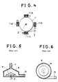
- pumps of this kind which are designed, for example, as shown in Figs. 5 and 6. More specifically, such a pump comprises a vessel (a), an outlet opening (b) provided in a tangential direction of an outer periphery at the lower part of the vessel (a),and an inlet (c) in the central portion at the upper part of the vessel (a).
- a sealed rotary shaft (d) is provided in the central portion at the lower part of the vessel (a), the rotary shaft (d) being extended within the vessel (a),an umbrella-like rotor (e) is secured to the end of the shaft, the rotor (e) being rotated by a drive device not shown from the bottom.
- the liquid flowing into the vessel (a) from the upper inlet (c) is rotated by the rotation of the rotor (e) and formed into a centrifugal flow which flows out of the outlet opening (b).
- a pump by vessel revolution which comprises a vessel having an inlet and an outlet for a liquid, whereby said vessel is designed in such a manner that the vessel can be revolved in a direction around an axis (DE-C-486 575).
- an improvement in rotary pumps of the inclined disc type which comprises an inlet duct for admitting fluid to be pumped to the center region of a casing and an outlet duct at the periphery of the casing and electromagnets to induce a swashing motion in the disc whereby fluid is pumped from the inlet to the outlet duct (GB-A-771 840).
- the rotor rotates within the vessel and therefore various germs, air, foreign matters or the like are possibly mixed, which might cause hemolysis (destruction of red blood) or thrombus (condensation of blood).
- hemolysis destruction of red blood
- thrombus condensation of blood
- a bearing for rotating the rotor is provided on the vessel, the durability of the bearing portion, particularly a seal of the bearing has disadvantages.
- the disadvantage of the pump as disclosed by DE-C-486 575 lies in the fact that the liquid within the vessel rotates as a ring comprising a center of air.
- annular disc of soft iron is required which is located in a brass casing which provides two conic surfaces. Whereas the casing of this pump does not move, the annular disc moves due to the forces of electromagnets.
- the additional disc implies a complicated construction of the pump.
- the object of the present invention is to eliminate the need of a rotating means within the vessel and further to eliminate a seal of bearing for a rotary shaft of said rotating means accordingly.
- the fluid flowing into the vessel from the inlet gives rise to a circular motion to produce a centrifugal flow. Since in the outer peripheral tangential direction, the outlet opening is provided in the same direction as the revolution, the liquid flows out of the vessel according to the revolving speed of the vessel. Therefore, when the pump is used for the device for circulating blood such as an artificial heart or assisted circulation, the blood is completely shut off from outside to free from entry of various germs, air, foreign matters or the like. Still, by means of the invention the construction can be simplified so as to provide high reliability and durability.
- Fig. 1 shows the relationship between the eccentric distance form the center of revolution of a vessel and the discharge pressure as obtained by experiment.
- the eccentric distance was variously changed to obtain the respective discharge pressure.
- the number of revolutions of the vessel was 960 r.p.m.
- FIG. 2 shows a first embodiment of the invention.
- a vessel indicated at 1 which is formed of synthetic resin or the like, has an inlet 2 in the vicinity of a center position at the upper part thereof and an outlet opening 3 in a tangential direction of an outer peripheral portion thereof, and is rotatably held by means such as a flexible pipe or a roller provided on the lower surface of the vessel.
- a projected recess 4 is provided in the lower surface of the vessel 1, and an electric motor 6 having a crank-like rotary shaft 5 loosely fitted into the recess 4 is provided at the lower part of the vessel 1, the rotational direction of the motor 6 being preset so as to be the same as the tangential direction of the outlet opening 3.
- the end of the inlet 2 and the end of the outlet opening 3 are connected by a flexible pipe or the like for free revolution of the vessel 1.
- the liquid flows in from the inlet 2 of the vessel and the motor 6 is energized to rotate the shaft 5. Accordingly, the liquid within the vessel 1 gives rise to a circular motion to generate a centrifugal flow or eddy current and flows out of the outlet opening 3.
- the speed of the liquid to be flowed out is related to the speed of revolution of the vessel 1 and can be adjusted by the inside diameter of the outlet opening 3, the shape of a connecting portion with the vessel 1, and the like.
- a bugle-like membrane 8 formed of a flexible synthetic resin material comprising a soft film is secured at upper and lower ends to the vessel 1, and air or other gas 9 is sealed in a space between the vessel 1 and the membrane 8.
- Fig. 3 shows a second embodiment, in which the vessel 1 is supported by a tray-like support member 10 having at the lower surface thereof a recess 4 loosely fitted into the shaft 5.
- a tray-like support member 10 having at the lower surface thereof a recess 4 loosely fitted into the shaft 5.
- Fig. 4 shows a third embodiment, which shows another example of a driving device for revolving the vessel 1, in which the vessel 1 is formed of an electromagnetic material such as permalloy and provided on the lower surface.
- Electromagnetic coils 11a, 11b, 11c and 11d are provided opposedly to the side of the vessel 1 at intervals, and when pulses from an oscillator are successively applied to the electromagnetic coils 11a, 11b, 11c,11d, 11a, 11b..., the vessel 1 is revolved.
- the connecting mechanism such as the recess 4 and the shaft 5 in the previously described embodiment is not provided, and therefore there occurs no mechanical wear,noises and the like, thus providing an excellent durability.
Landscapes
- Health & Medical Sciences (AREA)
- Engineering & Computer Science (AREA)
- Heart & Thoracic Surgery (AREA)
- Mechanical Engineering (AREA)
- Life Sciences & Earth Sciences (AREA)
- Anesthesiology (AREA)
- Biomedical Technology (AREA)
- Hematology (AREA)
- Cardiology (AREA)
- Animal Behavior & Ethology (AREA)
- General Health & Medical Sciences (AREA)
- Public Health (AREA)
- Veterinary Medicine (AREA)
- General Engineering & Computer Science (AREA)
- Structures Of Non-Positive Displacement Pumps (AREA)
- External Artificial Organs (AREA)
Claims (6)
- Pumpe mit sich drehendem Behälter, enthaltend1.1 einen Behälter (1),1.1.1 mit einem Einlaß (2), der in der Mitte des Behälters (1) angebracht ist,1.1.2 und einem Auslaß (3), der in tangentialer Richtung eines äußeren Umfangsbereichs des Behälters (1) vorgesehen ist;1.2 eine Vorrichtung (4 bis 6), die den Behälter (1) um eine Achse dreht;
dadurch gekennzeichnet, daß1.3 eine hornförmige Membran (8) aus flexiblem Kunststoff an ihren oberen und unteren Enden an dem Behälter(1) befestigt und in dem Behälter (1) angebracht ist;1.4 ein Gas (9) zwischen dem Behälter (1) und der Membran (8) luftdicht eingeschlossen ist. - Pumpe nach Anspruch 1, dadurch gekennzeichnet, daß ein Elektromotor (6) unter dem Behälter (1) vorgesehen ist und daß ein Ende einer kurbelförmigen Drehwelle (5) des Motors (6) drehbar mit dem mittleren Bereich des unteren Bereichs des Behälters (1) verbunden ist.
- Pumpe nach Anspruch 1, dadurch gekennzeichnet, daß das Volumenverhältnis des Gases (9) zwischen dem Behälter (1) und der Membran (8) acht bis zwölf Prozent beträgt.
- Pumpe nach Anspruch 1, dadurch gekennzeichnet, daß der Behälter (1) aus elektromagnetischem Material hergestellt ist und mehrere elektromagnetische Spulen (11a bis 11d) seitlich vom Behälter (1) angeordnet sind, wobei diese elektromagnetischen Spulen (11a bis 11d) nacheinander pulsweise mit Energie beaufschlagt werden.
- Pumpe nach Anspruch 1, dadurch gekennzeichnet, daß der Behälter (1) von einem trogförmigen Halteelement (10) getragen wird, das auf seiner Unterseite eine Aussparung (4) aufweist, in die eine Welle (5) lose eingreift.
- Pumpe nach Anspruch 1, dadurch gekennzeichnet, daß an dem Ende einer Welle eine Aussparung vorgesehen ist, so daß ein auf der Unterseite des Behälters (1) oder eines Halteelements (10) befindlicher Vorsprung lose in die Aussparung eingreift.
Applications Claiming Priority (2)
| Application Number | Priority Date | Filing Date | Title |
|---|---|---|---|
| JP97436/87 | 1987-04-22 | ||
| JP62097436A JP2516766B2 (ja) | 1987-04-22 | 1987-04-22 | 容器揺動型遠心ポンプ |
Publications (3)
| Publication Number | Publication Date |
|---|---|
| EP0287924A2 EP0287924A2 (de) | 1988-10-26 |
| EP0287924A3 EP0287924A3 (en) | 1990-03-21 |
| EP0287924B1 true EP0287924B1 (de) | 1992-09-09 |
Family
ID=14192316
Family Applications (1)
| Application Number | Title | Priority Date | Filing Date |
|---|---|---|---|
| EP88105751A Expired - Lifetime EP0287924B1 (de) | 1987-04-22 | 1988-04-12 | Drehfasspumpe |
Country Status (4)
| Country | Link |
|---|---|
| US (2) | US4869650A (de) |
| EP (1) | EP0287924B1 (de) |
| JP (1) | JP2516766B2 (de) |
| DE (1) | DE3874392T2 (de) |
Families Citing this family (2)
| Publication number | Priority date | Publication date | Assignee | Title |
|---|---|---|---|---|
| DE19827408A1 (de) * | 1998-06-19 | 1999-12-30 | Roland Ernst Stiftung Fuer Ges | Fluidpumpenanordnung |
| JPWO2023199602A1 (de) * | 2022-04-12 | 2023-10-19 |
Family Cites Families (11)
| Publication number | Priority date | Publication date | Assignee | Title |
|---|---|---|---|---|
| DE486575C (de) * | 1928-12-28 | 1929-11-25 | Goedhart A G Geb | Schleuderpumpe |
| US2674404A (en) * | 1950-12-26 | 1954-04-06 | Allis Louis Co | Turbocompressor for refrigerating apparatus |
| GB771840A (en) * | 1954-12-14 | 1957-04-03 | Jack Jones | Improvement in rotary pumps of the inclined disc type |
| US3082940A (en) * | 1960-03-29 | 1963-03-26 | Frantz Electric Ind Inc | Vacuum cleaners |
| US3617153A (en) * | 1970-02-02 | 1971-11-02 | Robert C Mowry | Hydraulic cycle pump |
| AT309231B (de) * | 1971-05-27 | 1973-08-10 | Vortex Pumpen Ag | Kreiselpumpe zum Einbau in Rohrleitungssysteme |
| US3746465A (en) * | 1971-08-11 | 1973-07-17 | Lummus Industries | Centrifugal fan for handling material |
| US4120616A (en) * | 1975-10-06 | 1978-10-17 | Breuer Electric Manufacturing Company | Vacuum cleaner-blower assembly with sound absorbing arrangement |
| SU987208A1 (ru) * | 1980-11-17 | 1983-01-07 | Челябинский Политехнический Институт Им.Ленинского Комсомола | Устройство дл перекачивани жидких и двухфазных сред |
| SU1002682A1 (ru) * | 1981-10-01 | 1983-03-07 | Ереванский Электроламповый Завод | Инерционный насос |
| SU1092307A1 (ru) * | 1983-03-11 | 1984-05-15 | Специальное конструкторское бюро прикладной геофизики СО АН СССР | Вибронасос |
-
1987
- 1987-04-22 JP JP62097436A patent/JP2516766B2/ja not_active Expired - Lifetime
-
1988
- 1988-04-12 DE DE8888105751T patent/DE3874392T2/de not_active Expired - Fee Related
- 1988-04-12 EP EP88105751A patent/EP0287924B1/de not_active Expired - Lifetime
- 1988-04-22 US US07/185,029 patent/US4869650A/en not_active Expired - Lifetime
-
1989
- 1989-05-16 US US07/352,344 patent/US4961692A/en not_active Expired - Lifetime
Also Published As
| Publication number | Publication date |
|---|---|
| JP2516766B2 (ja) | 1996-07-24 |
| EP0287924A3 (en) | 1990-03-21 |
| US4869650A (en) | 1989-09-26 |
| US4961692A (en) | 1990-10-09 |
| JPS63263290A (ja) | 1988-10-31 |
| EP0287924A2 (de) | 1988-10-26 |
| DE3874392T2 (de) | 1993-04-08 |
| DE3874392D1 (de) | 1992-10-15 |
Similar Documents
| Publication | Publication Date | Title |
|---|---|---|
| EP1186310B1 (de) | Turboblutpumpe | |
| US5017103A (en) | Centrifugal blood pump and magnetic coupling | |
| EP0425257B1 (de) | Zentrifugalblutpumpe | |
| US5399074A (en) | Motor driven sealless blood pump | |
| JP3582467B2 (ja) | ターボ式血液ポンプ | |
| US5658136A (en) | Centrifugal blood pump | |
| JP3187080B2 (ja) | 液体の体外循環用の液体遠心ポンプ | |
| EP0810374B1 (de) | Kreiselpumpenaggregat | |
| JP2989233B2 (ja) | ターボ形ポンプ | |
| US5338158A (en) | Pressure exchanger having axially inclined rotor ducts | |
| US3575536A (en) | Pump for beverage dispenser | |
| EP0287924B1 (de) | Drehfasspumpe | |
| US4722660A (en) | Centrifugal pump with a nutating impeller | |
| JP2848415B2 (ja) | 遠心血液ポンプ | |
| WO1992021388A1 (en) | Pump | |
| US4818193A (en) | Centrifugal pump selectively mountable in centerline or inline position | |
| EP0421280B1 (de) | Präzessionspumpe mit komplett eingebautem Motor | |
| JPH04112994A (ja) | ターボ形ポンプ | |
| JP3247718B2 (ja) | 血液ポンプ | |
| CA2014078C (en) | Centrifugal blood pump and motor drive | |
| JP3712051B2 (ja) | 遠心型血液ポンプ装置 | |
| HK1007519B (en) | Centrifugal blood pump and motor drive | |
| JPH06173900A (ja) | 揺動円盤を備えたポンプ | |
| US3972483A (en) | Pumping and pulverizing apparatus | |
| HK1007520A1 (en) | Centrifugal blood pump and motor drive |
Legal Events
| Date | Code | Title | Description |
|---|---|---|---|
| PUAI | Public reference made under article 153(3) epc to a published international application that has entered the european phase |
Free format text: ORIGINAL CODE: 0009012 |
|
| AK | Designated contracting states |
Kind code of ref document: A2 Designated state(s): DE FR GB |
|
| PUAL | Search report despatched |
Free format text: ORIGINAL CODE: 0009013 |
|
| AK | Designated contracting states |
Kind code of ref document: A3 Designated state(s): DE FR GB |
|
| 17P | Request for examination filed |
Effective date: 19900220 |
|
| 17Q | First examination report despatched |
Effective date: 19901022 |
|
| GRAA | (expected) grant |
Free format text: ORIGINAL CODE: 0009210 |
|
| AK | Designated contracting states |
Kind code of ref document: B1 Designated state(s): DE FR GB |
|
| REF | Corresponds to: |
Ref document number: 3874392 Country of ref document: DE Date of ref document: 19921015 |
|
| ET | Fr: translation filed | ||
| PLBE | No opposition filed within time limit |
Free format text: ORIGINAL CODE: 0009261 |
|
| STAA | Information on the status of an ep patent application or granted ep patent |
Free format text: STATUS: NO OPPOSITION FILED WITHIN TIME LIMIT |
|
| 26N | No opposition filed | ||
| REG | Reference to a national code |
Ref country code: GB Ref legal event code: IF02 |
|
| PGFP | Annual fee paid to national office [announced via postgrant information from national office to epo] |
Ref country code: FR Payment date: 20020215 Year of fee payment: 15 |
|
| PGFP | Annual fee paid to national office [announced via postgrant information from national office to epo] |
Ref country code: GB Payment date: 20020410 Year of fee payment: 15 |
|
| PGFP | Annual fee paid to national office [announced via postgrant information from national office to epo] |
Ref country code: DE Payment date: 20020420 Year of fee payment: 15 |
|
| PG25 | Lapsed in a contracting state [announced via postgrant information from national office to epo] |
Ref country code: GB Free format text: LAPSE BECAUSE OF NON-PAYMENT OF DUE FEES Effective date: 20030412 |
|
| PG25 | Lapsed in a contracting state [announced via postgrant information from national office to epo] |
Ref country code: DE Free format text: LAPSE BECAUSE OF NON-PAYMENT OF DUE FEES Effective date: 20031101 |
|
| GBPC | Gb: european patent ceased through non-payment of renewal fee |
Effective date: 20030412 |
|
| PG25 | Lapsed in a contracting state [announced via postgrant information from national office to epo] |
Ref country code: FR Free format text: LAPSE BECAUSE OF NON-PAYMENT OF DUE FEES Effective date: 20031231 |
|
| REG | Reference to a national code |
Ref country code: FR Ref legal event code: ST |