EP0287950A2 - Seringue de sécurite à usage unique - Google Patents
Seringue de sécurite à usage unique Download PDFInfo
- Publication number
- EP0287950A2 EP0287950A2 EP19880105950 EP88105950A EP0287950A2 EP 0287950 A2 EP0287950 A2 EP 0287950A2 EP 19880105950 EP19880105950 EP 19880105950 EP 88105950 A EP88105950 A EP 88105950A EP 0287950 A2 EP0287950 A2 EP 0287950A2
- Authority
- EP
- European Patent Office
- Prior art keywords
- needle
- syringe
- container
- tubular sleeve
- tube sleeve
- Prior art date
- Legal status (The legal status is an assumption and is not a legal conclusion. Google has not performed a legal analysis and makes no representation as to the accuracy of the status listed.)
- Granted
Links
- 230000001681 protective effect Effects 0.000 claims abstract description 17
- 239000007788 liquid Substances 0.000 claims abstract description 10
- 238000002347 injection Methods 0.000 claims description 21
- 239000007924 injection Substances 0.000 claims description 21
- 238000007789 sealing Methods 0.000 claims description 14
- 239000002775 capsule Substances 0.000 claims description 2
- 230000000694 effects Effects 0.000 claims description 2
- 239000012528 membrane Substances 0.000 claims description 2
- 230000008878 coupling Effects 0.000 claims 2
- 238000010168 coupling process Methods 0.000 claims 2
- 238000005859 coupling reaction Methods 0.000 claims 2
- 208000014674 injury Diseases 0.000 description 5
- 208000027418 Wounds and injury Diseases 0.000 description 4
- 230000006378 damage Effects 0.000 description 4
- 208000015181 infectious disease Diseases 0.000 description 3
- 238000006073 displacement reaction Methods 0.000 description 2
- 230000000414 obstructive effect Effects 0.000 description 2
- 239000000523 sample Substances 0.000 description 2
- 208000012260 Accidental injury Diseases 0.000 description 1
- 239000003708 ampul Substances 0.000 description 1
- 238000005452 bending Methods 0.000 description 1
- 210000001124 body fluid Anatomy 0.000 description 1
- 239000010839 body fluid Substances 0.000 description 1
- 238000011109 contamination Methods 0.000 description 1
- 239000003814 drug Substances 0.000 description 1
- 229940079593 drug Drugs 0.000 description 1
- 239000011521 glass Substances 0.000 description 1
- 239000012678 infectious agent Substances 0.000 description 1
- 238000000034 method Methods 0.000 description 1
- 230000001225 therapeutic effect Effects 0.000 description 1
Images



Classifications
-
- A—HUMAN NECESSITIES
- A61—MEDICAL OR VETERINARY SCIENCE; HYGIENE
- A61M—DEVICES FOR INTRODUCING MEDIA INTO, OR ONTO, THE BODY; DEVICES FOR TRANSDUCING BODY MEDIA OR FOR TAKING MEDIA FROM THE BODY; DEVICES FOR PRODUCING OR ENDING SLEEP OR STUPOR
- A61M5/00—Devices for bringing media into the body in a subcutaneous, intra-vascular or intramuscular way; Accessories therefor, e.g. filling or cleaning devices, arm-rests
- A61M5/178—Syringes
- A61M5/31—Details
- A61M5/32—Needles; Details of needles pertaining to their connection with syringe or hub; Accessories for bringing the needle into, or holding the needle on, the body; Devices for protection of needles
- A61M5/3205—Apparatus for removing or disposing of used needles or syringes, e.g. containers; Means for protection against accidental injuries from used needles
- A61M5/321—Means for protection against accidental injuries by used needles
- A61M5/322—Retractable needles, i.e. disconnected from and withdrawn into the syringe barrel by the piston
-
- A—HUMAN NECESSITIES
- A61—MEDICAL OR VETERINARY SCIENCE; HYGIENE
- A61M—DEVICES FOR INTRODUCING MEDIA INTO, OR ONTO, THE BODY; DEVICES FOR TRANSDUCING BODY MEDIA OR FOR TAKING MEDIA FROM THE BODY; DEVICES FOR PRODUCING OR ENDING SLEEP OR STUPOR
- A61M5/00—Devices for bringing media into the body in a subcutaneous, intra-vascular or intramuscular way; Accessories therefor, e.g. filling or cleaning devices, arm-rests
- A61M5/178—Syringes
- A61M5/31—Details
- A61M5/32—Needles; Details of needles pertaining to their connection with syringe or hub; Accessories for bringing the needle into, or holding the needle on, the body; Devices for protection of needles
- A61M5/3205—Apparatus for removing or disposing of used needles or syringes, e.g. containers; Means for protection against accidental injuries from used needles
- A61M5/321—Means for protection against accidental injuries by used needles
- A61M5/322—Retractable needles, i.e. disconnected from and withdrawn into the syringe barrel by the piston
- A61M5/3221—Constructional features thereof, e.g. to improve manipulation or functioning
- A61M2005/3227—Constructional features thereof, e.g. to improve manipulation or functioning the needle being retracted laterally outside the syringe barrel, e.g. with separate guideway
-
- A—HUMAN NECESSITIES
- A61—MEDICAL OR VETERINARY SCIENCE; HYGIENE
- A61M—DEVICES FOR INTRODUCING MEDIA INTO, OR ONTO, THE BODY; DEVICES FOR TRANSDUCING BODY MEDIA OR FOR TAKING MEDIA FROM THE BODY; DEVICES FOR PRODUCING OR ENDING SLEEP OR STUPOR
- A61M5/00—Devices for bringing media into the body in a subcutaneous, intra-vascular or intramuscular way; Accessories therefor, e.g. filling or cleaning devices, arm-rests
- A61M5/178—Syringes
- A61M5/31—Details
- A61M5/32—Needles; Details of needles pertaining to their connection with syringe or hub; Accessories for bringing the needle into, or holding the needle on, the body; Devices for protection of needles
- A61M5/3205—Apparatus for removing or disposing of used needles or syringes, e.g. containers; Means for protection against accidental injuries from used needles
- A61M5/321—Means for protection against accidental injuries by used needles
- A61M5/322—Retractable needles, i.e. disconnected from and withdrawn into the syringe barrel by the piston
- A61M5/3232—Semi-automatic needle retraction, i.e. in which triggering of the needle retraction requires a deliberate action by the user, e.g. manual release of spring-biased retraction means
Definitions
- the present invention relates to a disposable safety syringe.
- Syringes of this type are used, for example, to inject drugs or to withdraw body fluids for therapeutic purposes or for a medical examination.
- Disposable syringes are known to be commercially available in sterilized and ready-to-use condition, i.e. they are already provided with the associated injection needle, which is protected by a removable rigid cap or sheath.
- the injection needle of a disposable syringe protruding in the use position represents a serious risk of injury and infection for all those who can come into contact with such a syringe.
- the primary object of the invention is to design a disposable safety syringe in such a way that the disadvantages listed above are eliminated.
- the disposable safety syringe according to the invention is simple and convenient to use and function safely and reliably.
- the disposable safety syringe according to the invention should, if desired, be able to be equipped with two needles, for example in order to remove liquid from an ampoule or the human body with a sterile needle and to carry out the actual injection with the other sterile needle.
- Such a disposable safety syringe should finally allow liquids in ampoules, probes or the like. inject or remove from it without the injection needle being obstructive, although present in the syringe.
- the invention proposes a safety disposable syringe with the features specified in the characterizing part of claim 1.
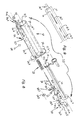
- a disposable safety syringe according to a first embodiment of the invention is designated in its entirety by 10 (FIGS. 1 and 2).
- the syringe 10 comprises a container 11 for liquid to be injected or aspirated, which is designed as a hollow cylinder 11.1 closed at one end by a bottom wall 11.2.
- the container 11 is made, for example, from a suitable plastic.
- a disc-shaped piston 12 with a flat head 12.1 is slidably arranged in the container 11 and is provided with a rubber-elastic sealing ring 12.3 inserted in a circumferential groove 12.2 for sealing the piston when it slides along the cylindrical inner wall of the container 11.
- a rigid, coaxial piston cross-shaped cross-section 13 is fixed.
- piston rod 13 has a grip part 13.1, which is used for manual actuation of the syringe, is also disk-shaped and is fastened to the end of the piston rod remote from the piston and protrudes outward through an opening 11.3 of the container 11.
- piston 12, piston rod 13 and handle part 13.1 are in one piece, e.g. made of plastic.
- the syringe 10 comprises a cylindrical tubular sleeve 14 which is formed in one piece with the container 11 and is arranged axially parallel to the hollow cylinder 11.1 of the container 11 and is tangent to it.
- the tubular sleeve 14 has at one axial end a conically tapered nozzle 14.1, which projects beyond the bottom wall 11.2 of the container 11 and is designed in a standardized design for detachable attachment of a common injection needle with a standardized needle holder (not shown).
- a frustoconical seat 14.2 is formed in the tubular sleeve 14 coaxially therewith; this is followed by a coaxial opening 14.3 with a conical countersink and a larger cone angle, towards the interior of the tubular sleeve 14, this opening merging into the cylindrical inner wall of the tubular sleeve 14 and being slightly behind the bottom wall 11.2 of the container 11.
- the frustoconical seat 14.2 in the nozzle 14.1 opens into a coaxial through hole 14.4.
- a protective cap 15 is placed on the nozzle 14.1.
- the tubular sleeve 14 has an opening 14.5 which lies approximately in one plane with the opening 11.3 of the container 11 and into a recessed opening which is open towards the interior of the tubular sleeve 14 and adjoins the cylindrical inner wall of the tubular sleeve 14.6 merges, this mouth being conical in the opposite direction to the countersunk mouth 14.3 of the frustoconical seat 14.2 in the nozzle 14.1.
- a transversely elongated flange 16 as a handle for the syringe 10 is integrally formed with these two parts on the outer circumference of the container 11 and the tubular sleeve 14.
- a radial through bore 17 connects the container 11 to the tubular sleeve 14 with a tight seal to the outside and is arranged in the wall region common to the container 11 and the tubular sleeve 14.
- This through hole 17 is located close to the bottom wall 11.2 of the container (end position of the injection stroke of the piston 12 in the container 11) and opens into the recessed opening 14.3 of the frustoconical seat 14.2 in the nozzle 14.1 of the tubular sleeve.
- the syringe 10 also comprises a hollow needle 18, which is carried by a coaxial, bush-shaped, partially hollow and sealably displaceable needle holder 18.1 arranged in the cylindrical tube sleeve 14, the needle 18 being coaxial and directed towards the through hole 14.4 of the nozzle 14.1.
- the sleeve-shaped needle holder 18.1 consists of a substantially cylindrical body 18.2 and carries the needle 18 on the coaxially projecting frustoconical head 18.3 at the free end of the smaller diameter.
- the cylindrical body 18.2 of the sleeve-shaped needle holder has on its outer circumference a first circumferential groove 18.4 which is close to the Needle 18 extends, and a further circumferential groove 18.5, which is further away from the needle 18.
- first circumferential groove 18.4 there are two radial, diametrically opposed bores 18.6 (FIG. 3) in the needle holder, which open into the interior of the needle holder, while a rubber-elastic sealing ring 18.7 is inserted in the further circumferential groove 18.5 in order to seal the needle holder in a sealed manner ensure along the cylindrical inner wall of the tubular sleeve 14.
- FIG. 3 shows the interior of the Needle holder 18.1 formed by an axial bore 18.8, which is used in the frustoconical head 18.3 of the needle holder for mounting the needle 18 and forms an extension of the needle bore, this axial bore 18.8 extending further in the cylindrical body 18.2 of the holder up to the radial bores 18.6, which thereby in connection with the axial bore 18.8.
- the needle holder 18.1 is fastened to a rigid coaxial shaft 19 of cross-shaped cross section in the exemplary embodiment shown.
- the shaft 19 At its free end projecting from the cylindrical body 14 through the opening 14.5, the shaft 19 has a disk-shaped actuating part 19.1. Needle holder 18.1, shaft 19 and actuating part 19.1 are made in one piece from plastic in the exemplary embodiment shown.
- the shaft 19 has a constriction 19.2 of its cross section approximately in the middle of its length, which due to the reduced strength thereby forms a fracture point of the shaft, as will be described in more detail below.
- the sleeve-shaped needle holder 18.1 is pressed in through the opening 14.5 of the tubular sleeve 14 beyond the recessed opening 14.6 of the sleeve.
- the disposable safety syringe according to a further exemplary embodiment of the invention is designated in its entirety by 20 (FIGS. 8, 10).
- the syringe 20 comprises a container 21, formed by a hollow cylinder 21.1, which is closed at one end by a bottom wall 21.2.
- a disk-shaped piston 22 with a flat head 22.1 and a rubber-elastic sealing ring 22.2 is slidably and securely displaceable.
- the piston 22 is fixedly connected to a rigid coaxial piston rod 23, the likewise disk-shaped coaxial actuating part 23.1 of which is fixed at the end of the piston rod facing away from the piston 22 through a container opening 21.3 projecting outwards.
- the syringe 20 in one-piece design with the container 21 has a cylindrical tubular sleeve 24 which is arranged axially parallel to the hollow cylinder 21.1 and is tangential to this.
- the tubular sleeve 24 has at one axial end a conically tapered nozzle 24.1 which projects over the bottom wall 21.2 of the container 21.
- a frustoconical seat 24.2 is formed in the tubular sleeve 24 coaxially therewith; this is followed by a coaxial opening 24.3 towards the interior of the tubular sleeve 24 with a conical countersink and a larger cone angle, the opening merging into the cylindrical inner wall of the tubular sleeve 24 and protrudes approximately to the rear relative to the bottom wall 21.2 of the container.
- the frustoconical seat 24.2 in the nozzle 24.1 opens into a coaxial through hole 24.4 which is open to the outside.
- a protective cap 25 is placed on the nozzle 24.1.
- the tubular sleeve 24 has an opening 24.5 which lies essentially in one plane with the opening 21.3 of the container 21.
- a flange 26 which is elongated in the transverse direction is formed on the outer circumference of the container and the tubular sleeve as a handle for the syringe 20.
- a radial through bore 27 connects the container 21 to the tubular sleeve 24 with a tight seal and is arranged in the wall region common to the container 21 and the tubular sleeve 24.
- This through hole 27 is located close to the bottom wall 21.2 of the container 21 (end position of the injection stroke of the piston 22 in the container) and opens into the recessed opening 24.3 of the frustoconical seat 24.2 in the nozzle 24.1 of the tubular sleeve.
- the cylindrical interior of the tubular sleeve 24 of the syringe 20 is in cross-section and, starting from the recessed opening 24.3 of the frustoconical seat 24.2, has a smaller diameter in a first short section 24.6 and in the second at the first section 24.6 and up to the opening 24.5 of the sleeve extending section 24.7 a large diameter.
- An annular step 24.8 is thereby formed between these two sections 24.6 and 24.7 in the cylindrical cavity of the tubular sleeve 24.
- the syringe 20 also comprises a hollow needle 28 which is carried by a coaxial, bush-shaped, partially hollow and sealed needle holder 28.1 which is arranged in the cylindrical tubular sleeve 24 and is displaceable, the needle 28 being coaxial and directed towards the through-bore 24.4 of the nozzle 24.1.
- the socket-shaped needle holder 28.1 comprises an approximately cylindrical intermediate body 28.2 and carries the needle 28 on the coaxially projecting frusto-conical head 28.3 at the free end of the smaller diameter.
- the cylindrical intermediate body 28.2 of the socket-shaped needle holder has a first circumferential groove 28.4 on its outer circumference, which is close to the needle 28 stretches, and another circumferential groove 28.5, which is further away from the needle.
- first circumferential groove 28.4 there are two radial diametrically opposed bores 28.6 (only one of which is visible in the figures) in the needle holder, which open into the interior of the needle holder, while a rubber-elastic sealing ring 28.7 is inserted in the further circumferential groove 28.5. in order to ensure the sealed sliding of the needle holder along the cylindrical inner wall in the region of the first section 24.6 of the tubular sleeve 24 with a smaller diameter.
- the needle holder 18.1 according to FIG.
- the (not shown) interior of the needle holder 28.1 of the syringe 20 is formed by an axial bore which in the frustoconical head 28.3 of the needle holder serves to support the needle 28 and forms an extension of the needle bore, this axial bore in the cylindrical intermediate body 28.2 of the holder extending up to the radial bore 28.6, whereby these are connected to the axial bore.
- the cylindrical intermediate body 28.2 has an integrally molded flange 28.8 of larger diameter, the circumferential surface of which serves as a sliding surface during the displacement in the section 24.7 of larger diameter of the cylindrical interior of the tubular sleeve 24.
- a return spring 29 is supported against one side of the flange, which is pushed coaxially onto the bush-shaped needle holder 28.1 and the other end of which is supported against the aforementioned annular step 24.8 in the interior of the tubular sleeve 24.
- the sleeve-shaped needle holder 28.1 is made, for example, in one piece from plastic.
- a sliding shoe 30 is adjustably arranged in the section 24.7 of larger diameter of the cylindrical interior of the tubular sleeve 24 and provided with a disk-shaped head 30.1, this head serving as a guide for the sliding movement in the space mentioned and from the front Arm 30.2 protrudes and on the opposite side of the container 21 from the surface of the mentioned Is arranged sliding along the interior.
- This arm which runs parallel to the shaft 28.9, has at its free end a control tooth 30.3, which projects radially through a longitudinal slot 31.1 in the tubular sleeve 24 on the side opposite the container 21 from the tubular sleeve 24 (FIG. 9).
- a support foot 30.4 extends behind the disk-shaped head 30.1 and slidably abuts on the side of the container 21 against the surface of the cylindrical interior of the tubular sleeve 24.
- a spring leaf 30.5 also protrudes in the direction toward the surface of the cylindrical interior on the side opposite the container and carries a latching tongue 30.6 at its free end, which can be separated by one of two longitudinal slots 31.2, 31.3 can emerge radially from the sleeve 24 in the tubular sleeve 24 (FIG. 9).
- the two slots are of different lengths (slot 31.2 is longer than slot 31.3) and are aligned the same under themselves and with respect to the guide slot 31.1.
- the latching tongue 30.6 is designed against the nozzle 24.1 of the tubular sleeve 24 in the manner of a slide, so as to facilitate the disengagement of one or the other slot when the slide shoe 30 moves in the direction of the nozzle 24.1, while on the other side the Latching tongue extends essentially normal to the axis of the tubular sleeve in order to ensure the latching position of the tongue with respect to the sliding shoe 30 against the force of the return spring 29.
- the free end of the shaft 28.9 of the needle holder 28.1 lies against the end face of the disk-shaped head 30.1 of the sliding block 30.
- the slide shoe 30 is made, for example, in one piece from plastic.
- the opening 24.5 of the tubular sleeve 24 is closed by means of a stopper 32 (FIGS. 10-14).
- the syringe 10 is presented ready for use in accordance with the illustration in FIG. 2, that is to say with the injection needle retracted in the tubular sleeve 14 in the safety position and with the protective cap 15 attached to the nozzle 14.1.
- the protective cap 15 is removed, the syringe is gripped on the flange 16 and then the needle 18 is pushed outward through the opening 14.4 of the nozzle 14.1 on the actuating part 19.1 of the shaft 19 by pushing pressure in the axial direction (arrow F1 in FIG. 2) shifted until the needle holder 18.1 has entered the mouth 14.3 of the frustoconical seat 14.2 of the nozzle.
- the frustoconical head 18.3 and the cylindrical body 18.2 of the needle holder are then pressed into the seat 14.2 or into the mouth 14.3, whereby the working position of the needle 18, which now protrudes completely from the tubular sleeve 14, is reached, thereby in the tube sleeve 14 a tightly closed space between the frustoconical head 18.3 in the conical seat and the sealing ring 18.7 on the needle holder 18.1 by contact of the sealing ring is formed on the cylindrical inner surface of the tubular sleeve 14 (FIG. 4).
- the needle 18 remaining enclosed in the tubular sleeve 14 in this way. Then the protective cap 15 is placed on the nozzle 14.1. The syringe 10 can thus be discarded with the greatest security. It should be noted that the needle holder 18.1 can in no way be pulled back out of the tube sleeve with the needle 18 because it would then get jammed in the recessed opening 14.6.
- the liquid can be sucked into the syringe by a conventional injection needle with a standardized needle carrier being attached to the nozzle 14.1 after the protective cap 15 has been removed, the needle 18 thus far being in protected position in the tubular sleeve 14 remains. After removal of the conventional needle mentioned, the needle 18 can then be driven out and the injection can be carried out, as described above.
- the syringe 10 can also advantageously be used when the needle 18 is retracted into the tubular sleeve 14, for example to dispense liquid in ampoules, probes or the like. inject or suck out of it without the needle being in any way obstructive.
- the syringe 10 is also for use as a test glass for taps or the like. suitable for laboratory work.
- the syringe 20 is presented ready for use as shown in FIG. 10.
- the protective cap 25 is removed and a sliding pressure is exerted on the slide shoe 30 via the control tooth 30.3 emerging from the guide slot 31.1 (FIG. 10, arrow F5).
- the latching tongue 30.6 is released from the slot 31.3 as a result of elastic bending of the leaflet 30.5 and engages in the next slot 31.2.
- the latching tongue 30.6 carries out an adjustment path which corresponds to the further displacement of the control tooth 30.3 in its guide slot 31.1 and the pressing in of the frustoconical head 28.3 and the cylindrical intermediate body 28.2 of the needle holder 28.1 into the mouth 24.2 or the seat 24.3 in the nozzle 24.1 of the tubular sleeve 24, the needle 28 completely protruding through the passage opening 24.4 of the nozzle (FIG. 11).
- the seal 28.7 ensures sealing against the wall in the region 24.6 of smaller diameter of the interior of the tube sleeve 24, while in this position of the needle holder 28.1 the annular groove 28.4 - into which the radial bores 28.6 open - with the sealed connecting bore 27 between the tube sleeve 24 and the container 21 covers.
- the needle 28 is now in the working position and the connection between the bore of the needle and the container 21 is made in the same way as described for the syringe 10.
- the return spring 29 is tensioned.
- the processes of sealed suction (FIG. 11, arrow F6) and injection (FIG. 12, arrow F7) are now carried out by moving the piston 22 in the container 21.
- the control tooth 30.3 is pulled in accordance with arrow F8 in FIG.
- the container of the syringe can contain a vacuum capsule (called "Vacutainer” in business), or it can be designed with an elastic membrane, while the needle holder and the tube sleeve can be given a different shape, but always the function of the sliding guide, the stable working position and the sealing of the needle in the needle protection sleeve.
- a vacuum capsule called "Vacutainer” in business
- the needle holder and the tube sleeve can be given a different shape, but always the function of the sliding guide, the stable working position and the sealing of the needle in the needle protection sleeve.
- connection between the needle bore and the container of the syringe can be realized via the tube sleeve instead of through the needle holder by the needle itself by making radial bores in the needle wall with suitable sealing means.
- the pipe sleeve in such a way that they can accommodate the adjustable needle with a seal and can ensure its stable working position, while the needle holder only takes over the function of the holder for the needle.
Landscapes
- Health & Medical Sciences (AREA)
- Engineering & Computer Science (AREA)
- Heart & Thoracic Surgery (AREA)
- Vascular Medicine (AREA)
- Anesthesiology (AREA)
- Biomedical Technology (AREA)
- Environmental & Geological Engineering (AREA)
- Hematology (AREA)
- Life Sciences & Earth Sciences (AREA)
- Animal Behavior & Ethology (AREA)
- General Health & Medical Sciences (AREA)
- Public Health (AREA)
- Veterinary Medicine (AREA)
- Infusion, Injection, And Reservoir Apparatuses (AREA)
Priority Applications (1)
| Application Number | Priority Date | Filing Date | Title |
|---|---|---|---|
| AT88105950T ATE82514T1 (de) | 1987-04-24 | 1988-04-14 | Sicherheits-wegwerfspritze. |
Applications Claiming Priority (4)
| Application Number | Priority Date | Filing Date | Title |
|---|---|---|---|
| IT67343/87A IT1217164B (it) | 1987-04-24 | 1987-04-24 | Siringa monouso di sicurezza |
| IT6734387 | 1987-04-24 | ||
| IT8767600A IT1211199B (it) | 1987-07-10 | 1987-07-10 | Siringa monouso di sicurezza |
| IT6760087 | 1987-07-10 |
Publications (3)
| Publication Number | Publication Date |
|---|---|
| EP0287950A2 true EP0287950A2 (fr) | 1988-10-26 |
| EP0287950A3 EP0287950A3 (en) | 1990-05-09 |
| EP0287950B1 EP0287950B1 (fr) | 1992-11-19 |
Family
ID=26329759
Family Applications (1)
| Application Number | Title | Priority Date | Filing Date |
|---|---|---|---|
| EP88105950A Expired - Lifetime EP0287950B1 (fr) | 1987-04-24 | 1988-04-14 | Seringue de sécurite à usage unique |
Country Status (4)
| Country | Link |
|---|---|
| US (1) | US4941883A (fr) |
| EP (1) | EP0287950B1 (fr) |
| DE (1) | DE3876000D1 (fr) |
| ES (1) | ES2037125T3 (fr) |
Cited By (15)
| Publication number | Priority date | Publication date | Assignee | Title |
|---|---|---|---|---|
| EP0326983A3 (en) * | 1988-02-04 | 1990-08-08 | Vabin International S.R.L. | A disposable safety syringe with hypodermic needle |
| DE3925834A1 (de) * | 1989-08-04 | 1991-02-14 | Avemaria Wolfgang | Injektionsspritze fuer einmalverwendung |
| FR2652006A1 (fr) * | 1989-09-15 | 1991-03-22 | Denis Roger | Dispositif de fabrication de seringues anticontagion. |
| WO1991010462A1 (fr) * | 1990-01-12 | 1991-07-25 | Malcolm Melville Davies | Ensembles a aiguille hypodermique |
| EP0426672A4 (en) * | 1988-04-18 | 1991-07-31 | Nujenko Pty Ltd | Single-use syringe |
| US5067947A (en) * | 1989-07-18 | 1991-11-26 | Tri/West Systems, Inc. | Syringe plunger rod mount |
| FR2664168A1 (fr) * | 1990-07-05 | 1992-01-10 | Buisson Philippe | Dispositif d'introduction d'au moins un objet dans un conduit corporel ou un espace tissulaire. |
| EP0479303A1 (fr) * | 1990-10-05 | 1992-04-08 | Amorino Morandini | Accessoire monté sur seringues pour permettre la retraction d'aiguille |
| WO1992017230A1 (fr) * | 1991-04-08 | 1992-10-15 | Habley Medical Technology Corporation | Seringue de securite a canule d'aiguille desaxee |
| WO1992017225A1 (fr) * | 1991-04-08 | 1992-10-15 | Habley Medical Technology Corporation | Seringue de securite a canule d'aiguille desaxee |
| EP0537248A4 (en) * | 1990-07-04 | 1993-12-22 | Maxwell Edmund Whisson | Improved parenteral device |
| US5300038A (en) * | 1993-04-30 | 1994-04-05 | Habley Medical Technology Corporation | Safety syringe with off-axis needle cannula |
| WO1998028031A1 (fr) * | 1996-12-23 | 1998-07-02 | H. Weidmann Ag | Canule pour seringues medicales |
| GB2508490A (en) * | 2011-12-06 | 2014-06-04 | Major Ltd C | A sharps retraction device |
| EP3384945A1 (fr) * | 2010-07-22 | 2018-10-10 | Becton, Dickinson and Company | Seringue à aiguille à rétraction passive et chambre double |
Families Citing this family (46)
| Publication number | Priority date | Publication date | Assignee | Title |
|---|---|---|---|---|
| WO1988008315A1 (fr) * | 1987-04-22 | 1988-11-03 | Maxwell Edmund Whisson | Dispositif parenteral |
| US5167641A (en) * | 1991-05-29 | 1992-12-01 | Arnis, Inc. | Auto-retracting needle injector system |
| US5232457A (en) * | 1991-08-05 | 1993-08-03 | Grim John P | Medical syringe |
| DE69228485T2 (de) | 1991-11-20 | 1999-10-21 | Eastland Technology Australia Pty. Ltd., Wangara | Zusatzgerät für eine parenterale vorrichtung |
| US5387195A (en) * | 1992-12-23 | 1995-02-07 | Hicks; Charles D. | No share syringe |
| EP0620018B1 (fr) * | 1993-03-12 | 1999-08-11 | Yoshikuni Saito | Seringue à aiguille rétractable |
| EP0703793B1 (fr) * | 1993-06-17 | 1998-11-25 | Farco-Pharma Gesellschaft Mit Beschränkter Haftung Pharmazeutische Präparate | Procede de fabrication d'un conditionnement sterile de produits prets-a-l'emploi et recipient pour ce conditionnement |
| CA2126478A1 (fr) * | 1993-06-29 | 1994-12-30 | Yoshikuni Saito | Corps de seringue, structure de connexion, seringue, piston, structure porte-aiguille, connecteur entre la structure porte-aiguille et la seringue, seringue assemblee et methode d'assemblage |
| US5445618A (en) * | 1994-01-18 | 1995-08-29 | Adobbati; Ricardo N. | Safety syringe with non-linear needle |
| US5573510A (en) * | 1994-02-28 | 1996-11-12 | Isaacson; Dennis R. | Safety intravenous catheter assembly with automatically retractable needle |
| AUPM859894A0 (en) | 1994-10-04 | 1994-10-27 | Eastland Technology Australia Pty Ltd | Syringe |
| US5658248A (en) * | 1995-08-04 | 1997-08-19 | Localmed, Inc. | Double-blind infusion device and method |
| US6093174A (en) * | 1998-05-21 | 2000-07-25 | Novinkov; Oleg L. | Pre-filled syringe with mechanism to store needle therein |
| US7435231B2 (en) | 1999-07-29 | 2008-10-14 | Fenwal, Inc. | Biological sample device receiver |
| US6530903B2 (en) | 2000-02-24 | 2003-03-11 | Xiping Wang | Safety syringe |
| US20020068907A1 (en) * | 2000-09-05 | 2002-06-06 | Dysarz Edward D. | Safety syringe with retraction trunk |
| US20030036725A1 (en) * | 2000-09-21 | 2003-02-20 | Gilad Lavi | Reconstitution and injection system |
| US6468250B2 (en) * | 2000-12-26 | 2002-10-22 | Kuo-Chen Yang | Dual-chamber safety hypodermic syringe |
| UY26711A1 (es) * | 2001-05-16 | 2001-12-28 | Mario Sangiovanni Sarmiento | Dispositivo portatubo jeringa de extracción de sangre para generación de vacío en el tubo |
| US6808512B1 (en) * | 2003-04-09 | 2004-10-26 | Hsiu-Chih Lin | Safety syringe |
| WO2005087102A1 (fr) * | 2004-03-15 | 2005-09-22 | Von Pace Pty Ltd | Dispositif a prelevements sanguins |
| FR2869533B1 (fr) * | 2004-05-03 | 2006-07-28 | Sedat Sa | Seringue pour interventions medicales et necessaire de reconstitution de substances extemporanees comportant une telle seringue |
| US7803132B2 (en) | 2004-10-14 | 2010-09-28 | Midland Medical Device Holdings, LLC | Safety medical syringe with retractable needle |
| US7846135B2 (en) * | 2006-02-24 | 2010-12-07 | Midland Medical Holding LLC | Retractable needle syringe with needle trap |
| JP4925716B2 (ja) * | 2006-04-28 | 2012-05-09 | メディキット株式会社 | 留置針組立体 |
| AU2007250532A1 (en) * | 2006-05-17 | 2007-11-22 | Eastland Medical Systems Ltd | Attachment for a parenteral device |
| CA2682699A1 (fr) * | 2007-03-21 | 2008-09-25 | Midland Medical Devices Holdings, Llc | Seringue medicale de securite avec aiguille retractable et comprenant un plongeur qui est recu dans un cylindre |
| US9308353B2 (en) | 2010-07-29 | 2016-04-12 | Retractable Technologies, Inc. | Needle retraction apparatus |
| US9381309B2 (en) | 2008-06-10 | 2016-07-05 | Retractable Technologies, Inc. | Frontal attachment device for syringe with pinch-activated retraction |
| US8323249B2 (en) | 2009-08-14 | 2012-12-04 | The Regents Of The University Of Michigan | Integrated vascular delivery system |
| US8814833B2 (en) | 2010-05-19 | 2014-08-26 | Tangent Medical Technologies Llc | Safety needle system operable with a medical device |
| WO2011146769A2 (fr) | 2010-05-19 | 2011-11-24 | Tangent Medical Technologies Llc | Système intégré d'administration vasculaire |
| US8556855B2 (en) * | 2010-07-22 | 2013-10-15 | Becton, Dickinson And Company | Dual chamber syringe with retractable needle |
| US8556854B2 (en) * | 2010-07-22 | 2013-10-15 | Becton, Dickinson And Company | Dual chamber syringe with retractable needle |
| US9550030B2 (en) * | 2010-07-22 | 2017-01-24 | Becton, Dickinson And Company | Dual chamber syringe with retractable needle |
| US10568554B2 (en) | 2012-12-14 | 2020-02-25 | Retractable Technologies, Inc. | Blood collection tube holder with slide-activated needle retraction |
| US9956352B2 (en) | 2012-12-14 | 2018-05-01 | Retractable Technologies, Inc. | Combined medical device with sliding frontal attachment and retractable needle |
| US9302055B2 (en) | 2012-12-14 | 2016-04-05 | Retractable Technologies, Inc. | Frontal attachment device for syringe with rotationally activated retractable needle |
| USD829891S1 (en) | 2012-12-14 | 2018-10-02 | Retractable Technologies, Inc. | Syringe with offset needle retraction chamber and frontal attachment |
| USD823463S1 (en) | 2012-12-14 | 2018-07-17 | Retractable Technologies, Inc. | Frontal attachment for medical device |
| USD823461S1 (en) | 2012-12-14 | 2018-07-17 | Retractable Technologies, Inc. | Slimline syringe with offset needle retraction chamber and frontal attachment |
| USD823457S1 (en) | 2012-12-14 | 2018-07-17 | Retractable Technologies, Inc. | Blood collection tube holder with offset needle retraction chamber and frontal attachment |
| US9320469B2 (en) | 2012-12-14 | 2016-04-26 | Retractable Technologies, Inc. | Retractable needle for blood gas sampling |
| CN104955507B (zh) | 2013-09-06 | 2019-12-31 | 托马斯·J·肖 | 具有滑动前端附接部及可回缩针的医疗装置 |
| JP6461174B2 (ja) | 2014-02-04 | 2019-01-30 | アイシーユー・メディカル・インコーポレーテッド | 自己プライミングシステムおよび自己プライミング方法 |
| US11340104B2 (en) * | 2020-07-07 | 2022-05-24 | Matthew Moers | Syringe with a valve in a housing for measuring chemicals |
Family Cites Families (9)
| Publication number | Priority date | Publication date | Assignee | Title |
|---|---|---|---|---|
| US857739A (en) * | 1906-10-16 | 1907-06-25 | Charles W Kennerly | Fountain hypodermic syringe. |
| US1930929A (en) * | 1931-05-12 | 1933-10-17 | Eisenberg Moses Joel | Hypodermic implement |
| DE1992767U (de) * | 1968-03-27 | 1968-08-29 | Peter Dr Pogacar | Vorrichtung zum feinstdosieren und einbringen von fluessigkeitsmengen zu analytischen oder behandlungszwecken in ein anderes medium. |
| US3923058A (en) * | 1972-05-19 | 1975-12-02 | Kendall & Co | Multi-chamber syringe |
| US4284077A (en) * | 1974-11-19 | 1981-08-18 | Wolfgang Wagner | Suction injector having an adjustable dosing device |
| US3978846A (en) * | 1975-01-02 | 1976-09-07 | Bailey Donald L | Syringe for taking blood samples |
| US4026287A (en) * | 1975-12-10 | 1977-05-31 | Irene Haller | Syringe with retractable cannula |
| US4655751A (en) * | 1986-02-14 | 1987-04-07 | Harbaugh John T | Liquid dispensing and receiving syringe |
| US4747830A (en) * | 1986-04-28 | 1988-05-31 | Gloyer Walter W | Anti-stick contagion free disposable hypodermic safety syringe |
-
1988
- 1988-04-14 ES ES198888105950T patent/ES2037125T3/es not_active Expired - Lifetime
- 1988-04-14 DE DE8888105950T patent/DE3876000D1/de not_active Expired - Lifetime
- 1988-04-14 EP EP88105950A patent/EP0287950B1/fr not_active Expired - Lifetime
- 1988-04-25 US US07/186,030 patent/US4941883A/en not_active Expired - Fee Related
Cited By (20)
| Publication number | Priority date | Publication date | Assignee | Title |
|---|---|---|---|---|
| EP0326983A3 (en) * | 1988-02-04 | 1990-08-08 | Vabin International S.R.L. | A disposable safety syringe with hypodermic needle |
| EP0426672A4 (en) * | 1988-04-18 | 1991-07-31 | Nujenko Pty Ltd | Single-use syringe |
| US5067947A (en) * | 1989-07-18 | 1991-11-26 | Tri/West Systems, Inc. | Syringe plunger rod mount |
| DE3925834A1 (de) * | 1989-08-04 | 1991-02-14 | Avemaria Wolfgang | Injektionsspritze fuer einmalverwendung |
| FR2652006A1 (fr) * | 1989-09-15 | 1991-03-22 | Denis Roger | Dispositif de fabrication de seringues anticontagion. |
| WO1991010462A1 (fr) * | 1990-01-12 | 1991-07-25 | Malcolm Melville Davies | Ensembles a aiguille hypodermique |
| EP0537248A4 (en) * | 1990-07-04 | 1993-12-22 | Maxwell Edmund Whisson | Improved parenteral device |
| FR2664168A1 (fr) * | 1990-07-05 | 1992-01-10 | Buisson Philippe | Dispositif d'introduction d'au moins un objet dans un conduit corporel ou un espace tissulaire. |
| EP0479303A1 (fr) * | 1990-10-05 | 1992-04-08 | Amorino Morandini | Accessoire monté sur seringues pour permettre la retraction d'aiguille |
| US5263942A (en) * | 1991-04-08 | 1993-11-23 | Habley Medical Technology Corporation | Packaged pharmaceutical-type safety syringe with off-axis needle cannula |
| WO1992017225A1 (fr) * | 1991-04-08 | 1992-10-15 | Habley Medical Technology Corporation | Seringue de securite a canule d'aiguille desaxee |
| US5267973A (en) * | 1991-04-08 | 1993-12-07 | Habley Medical Technology Corporation | Safety syringe with off-axis needle cannula |
| WO1992017230A1 (fr) * | 1991-04-08 | 1992-10-15 | Habley Medical Technology Corporation | Seringue de securite a canule d'aiguille desaxee |
| AU651454B2 (en) * | 1991-04-08 | 1994-07-21 | Habley Medical Technology Corporation | Safety syringe with off-axis needle cannula |
| US5300038A (en) * | 1993-04-30 | 1994-04-05 | Habley Medical Technology Corporation | Safety syringe with off-axis needle cannula |
| WO1998028031A1 (fr) * | 1996-12-23 | 1998-07-02 | H. Weidmann Ag | Canule pour seringues medicales |
| US6355017B2 (en) | 1996-12-23 | 2002-03-12 | H. Weidmann A.G. | Cannula for medical syringes |
| EP3384945A1 (fr) * | 2010-07-22 | 2018-10-10 | Becton, Dickinson and Company | Seringue à aiguille à rétraction passive et chambre double |
| GB2508490A (en) * | 2011-12-06 | 2014-06-04 | Major Ltd C | A sharps retraction device |
| GB2508490B (en) * | 2011-12-06 | 2014-10-22 | Major Ltd C | A sharps retraction device |
Also Published As
| Publication number | Publication date |
|---|---|
| ES2037125T3 (es) | 1993-06-16 |
| DE3876000D1 (de) | 1992-12-24 |
| EP0287950B1 (fr) | 1992-11-19 |
| US4941883A (en) | 1990-07-17 |
| EP0287950A3 (en) | 1990-05-09 |
Similar Documents
| Publication | Publication Date | Title |
|---|---|---|
| EP0287950B1 (fr) | Seringue de sécurite à usage unique | |
| DE68906278T2 (de) | Einziehbare einwegspritze. | |
| DE3874162T2 (de) | Spritze mit mitteln zum schutz gegen nadeleinstechen und medikamentenmissbrauch. | |
| DE69218592T2 (de) | Spritze | |
| DE60101307T2 (de) | Medizinische vorrichtung und verriegelungsmechanismus dafür | |
| DE69505142T2 (de) | Vorrichtungen zum zurückziehen von nadeln | |
| DE69428981T2 (de) | Spritze für subkutaninjektionen mit einer zurückziehbaren nadel | |
| DE2909002C3 (de) | Injektionsspritze für einmalige Verwendung | |
| DE69827395T2 (de) | Vorgefüllte injektionsvorrichtung mit zurückziehbarer nadel | |
| DE102008025011B4 (de) | Ampulle mit Ampullenhalterung | |
| DE69623268T2 (de) | Vorgefüllte spritze zur verabreichung von medikamenten | |
| DE69110050T2 (de) | Sicherheitsspritze mit zurückziehbarer hohlnadel. | |
| DE60107167T2 (de) | Hypodermische Spritze mit selektiv zurückziehbarer Nadel | |
| DE69724291T2 (de) | Spritze mit einziehbarer nadelvorrichtung | |
| DE60102526T2 (de) | Hypodermische Spritze mit selektiv zurückziehbarer Nadel | |
| DE68902781T2 (de) | Sicherheits-wegwerfspritze. | |
| DE69320862T2 (de) | Injektionsspritze mit geschützter Nadel | |
| DE69532869T2 (de) | Sicherheitsspritze | |
| DE19832834B4 (de) | Sicherheits-Infusions-Katheternadel | |
| CH433605A (de) | Einrichtung zum Mischen von zwei Stoffen und zum Füllen einer Spritze mit der Mischung | |
| DE69211356T2 (de) | Injektionsvorrichtung | |
| EP0957883A2 (fr) | Adaptateur utile pour prelever un liquide dans un recipient ferme par un bouchon | |
| EP0808148A1 (fr) | Dispositif de transfert | |
| CH691031A5 (de) | Zweiteilige Vorrichtung für die Verabreichung von Arzneimitteln. | |
| DE69728062T2 (de) | Injektionsspritze mit einer verschiebbaren nadelschutzvorrichtung |
Legal Events
| Date | Code | Title | Description |
|---|---|---|---|
| PUAI | Public reference made under article 153(3) epc to a published international application that has entered the european phase |
Free format text: ORIGINAL CODE: 0009012 |
|
| AK | Designated contracting states |
Kind code of ref document: A2 Designated state(s): AT BE CH DE ES FR GB LI LU NL SE |
|
| PUAL | Search report despatched |
Free format text: ORIGINAL CODE: 0009013 |
|
| AK | Designated contracting states |
Kind code of ref document: A3 Designated state(s): AT BE CH DE ES FR GB LI LU NL SE |
|
| 17P | Request for examination filed |
Effective date: 19900929 |
|
| 17Q | First examination report despatched |
Effective date: 19920207 |
|
| RAP3 | Party data changed (applicant data changed or rights of an application transferred) |
Owner name: VENTURINI, ALDO |
|
| GRAA | (expected) grant |
Free format text: ORIGINAL CODE: 0009210 |
|
| AK | Designated contracting states |
Kind code of ref document: B1 Designated state(s): AT BE CH DE ES FR GB LI LU NL SE |
|
| REF | Corresponds to: |
Ref document number: 82514 Country of ref document: AT Date of ref document: 19921215 Kind code of ref document: T |
|
| REF | Corresponds to: |
Ref document number: 3876000 Country of ref document: DE Date of ref document: 19921224 |
|
| GBT | Gb: translation of ep patent filed (gb section 77(6)(a)/1977) |
Effective date: 19921208 |
|
| ET | Fr: translation filed | ||
| REG | Reference to a national code |
Ref country code: ES Ref legal event code: FG2A Ref document number: 2037125 Country of ref document: ES Kind code of ref document: T3 |
|
| EPTA | Lu: last paid annual fee | ||
| PLBE | No opposition filed within time limit |
Free format text: ORIGINAL CODE: 0009261 |
|
| STAA | Information on the status of an ep patent application or granted ep patent |
Free format text: STATUS: NO OPPOSITION FILED WITHIN TIME LIMIT |
|
| 26N | No opposition filed | ||
| EAL | Se: european patent in force in sweden |
Ref document number: 88105950.5 |
|
| PGFP | Annual fee paid to national office [announced via postgrant information from national office to epo] |
Ref country code: FR Payment date: 19990402 Year of fee payment: 12 |
|
| PGFP | Annual fee paid to national office [announced via postgrant information from national office to epo] |
Ref country code: BE Payment date: 19990406 Year of fee payment: 12 |
|
| PGFP | Annual fee paid to national office [announced via postgrant information from national office to epo] |
Ref country code: SE Payment date: 19990408 Year of fee payment: 12 |
|
| PGFP | Annual fee paid to national office [announced via postgrant information from national office to epo] |
Ref country code: LU Payment date: 19990409 Year of fee payment: 12 Ref country code: AT Payment date: 19990409 Year of fee payment: 12 |
|
| PGFP | Annual fee paid to national office [announced via postgrant information from national office to epo] |
Ref country code: GB Payment date: 19990412 Year of fee payment: 12 |
|
| PGFP | Annual fee paid to national office [announced via postgrant information from national office to epo] |
Ref country code: ES Payment date: 19990416 Year of fee payment: 12 |
|
| PGFP | Annual fee paid to national office [announced via postgrant information from national office to epo] |
Ref country code: DE Payment date: 19990422 Year of fee payment: 12 |
|
| PGFP | Annual fee paid to national office [announced via postgrant information from national office to epo] |
Ref country code: CH Payment date: 19990423 Year of fee payment: 12 |
|
| PGFP | Annual fee paid to national office [announced via postgrant information from national office to epo] |
Ref country code: NL Payment date: 19990429 Year of fee payment: 12 |
|
| PG25 | Lapsed in a contracting state [announced via postgrant information from national office to epo] |
Ref country code: LU Free format text: LAPSE BECAUSE OF NON-PAYMENT OF DUE FEES Effective date: 20000414 Ref country code: GB Free format text: LAPSE BECAUSE OF NON-PAYMENT OF DUE FEES Effective date: 20000414 Ref country code: AT Free format text: LAPSE BECAUSE OF NON-PAYMENT OF DUE FEES Effective date: 20000414 |
|
| PG25 | Lapsed in a contracting state [announced via postgrant information from national office to epo] |
Ref country code: SE Free format text: LAPSE BECAUSE OF NON-PAYMENT OF DUE FEES Effective date: 20000415 Ref country code: ES Free format text: THE PATENT HAS BEEN ANNULLED BY A DECISION OF A NATIONAL AUTHORITY Effective date: 20000415 |
|
| PG25 | Lapsed in a contracting state [announced via postgrant information from national office to epo] |
Ref country code: LI Free format text: LAPSE BECAUSE OF NON-PAYMENT OF DUE FEES Effective date: 20000430 Ref country code: CH Free format text: LAPSE BECAUSE OF NON-PAYMENT OF DUE FEES Effective date: 20000430 Ref country code: BE Free format text: LAPSE BECAUSE OF NON-PAYMENT OF DUE FEES Effective date: 20000430 |
|
| BERE | Be: lapsed |
Owner name: VENTURINI ALDO Effective date: 20000430 |
|
| PG25 | Lapsed in a contracting state [announced via postgrant information from national office to epo] |
Ref country code: NL Free format text: LAPSE BECAUSE OF NON-PAYMENT OF DUE FEES Effective date: 20001101 |
|
| GBPC | Gb: european patent ceased through non-payment of renewal fee |
Effective date: 20000414 |
|
| EUG | Se: european patent has lapsed |
Ref document number: 88105950.5 |
|
| REG | Reference to a national code |
Ref country code: CH Ref legal event code: PL |
|
| PG25 | Lapsed in a contracting state [announced via postgrant information from national office to epo] |
Ref country code: FR Free format text: LAPSE BECAUSE OF NON-PAYMENT OF DUE FEES Effective date: 20001229 |
|
| NLV4 | Nl: lapsed or anulled due to non-payment of the annual fee |
Effective date: 20001101 |
|
| PG25 | Lapsed in a contracting state [announced via postgrant information from national office to epo] |
Ref country code: DE Free format text: LAPSE BECAUSE OF NON-PAYMENT OF DUE FEES Effective date: 20010201 |
|
| REG | Reference to a national code |
Ref country code: FR Ref legal event code: ST |
|
| REG | Reference to a national code |
Ref country code: ES Ref legal event code: FD2A Effective date: 20020204 |