EP0287984B1 - Kreiselpumpe für elektrische Haushaltsgeräte, wie Waschmaschinen, Geschirrspülmaschinen und ähnliches - Google Patents
Kreiselpumpe für elektrische Haushaltsgeräte, wie Waschmaschinen, Geschirrspülmaschinen und ähnliches Download PDFInfo
- Publication number
- EP0287984B1 EP0287984B1 EP88106126A EP88106126A EP0287984B1 EP 0287984 B1 EP0287984 B1 EP 0287984B1 EP 88106126 A EP88106126 A EP 88106126A EP 88106126 A EP88106126 A EP 88106126A EP 0287984 B1 EP0287984 B1 EP 0287984B1
- Authority
- EP
- European Patent Office
- Prior art keywords
- impeller
- cylindrical body
- centrifugal pump
- shaft
- rotor
- Prior art date
- Legal status (The legal status is an assumption and is not a legal conclusion. Google has not performed a legal analysis and makes no representation as to the accuracy of the status listed.)
- Expired - Lifetime
Links
- 238000005406 washing Methods 0.000 title claims description 4
- 238000005192 partition Methods 0.000 claims description 4
- 239000012530 fluid Substances 0.000 claims description 2
- 238000013016 damping Methods 0.000 claims 1
- 230000002452 interceptive effect Effects 0.000 claims 1
- 230000002093 peripheral effect Effects 0.000 claims 1
- 230000008878 coupling Effects 0.000 abstract description 5
- 238000010168 coupling process Methods 0.000 abstract description 5
- 238000005859 coupling reaction Methods 0.000 abstract description 5
- 239000007788 liquid Substances 0.000 abstract description 5
- 239000000428 dust Substances 0.000 abstract description 3
- 230000000903 blocking effect Effects 0.000 abstract 1
- 230000000295 complement effect Effects 0.000 abstract 1
- 239000000463 material Substances 0.000 description 2
- XLYOFNOQVPJJNP-UHFFFAOYSA-N water Substances O XLYOFNOQVPJJNP-UHFFFAOYSA-N 0.000 description 2
- 239000004519 grease Substances 0.000 description 1
- 230000000670 limiting effect Effects 0.000 description 1
- 230000005923 long-lasting effect Effects 0.000 description 1
- 239000013528 metallic particle Substances 0.000 description 1
- 238000000926 separation method Methods 0.000 description 1
Images

Classifications
-
- A—HUMAN NECESSITIES
- A47—FURNITURE; DOMESTIC ARTICLES OR APPLIANCES; COFFEE MILLS; SPICE MILLS; SUCTION CLEANERS IN GENERAL
- A47L—DOMESTIC WASHING OR CLEANING; SUCTION CLEANERS IN GENERAL
- A47L15/00—Washing or rinsing machines for crockery or tableware
- A47L15/42—Details
- A47L15/4214—Water supply, recirculation or discharge arrangements; Devices therefor
- A47L15/4225—Arrangements or adaption of recirculation or discharge pumps
-
- D—TEXTILES; PAPER
- D06—TREATMENT OF TEXTILES OR THE LIKE; LAUNDERING; FLEXIBLE MATERIALS NOT OTHERWISE PROVIDED FOR
- D06F—LAUNDERING, DRYING, IRONING, PRESSING OR FOLDING TEXTILE ARTICLES
- D06F39/00—Details of washing machines not specific to a single type of machines covered by groups D06F9/00 - D06F27/00
- D06F39/08—Liquid supply or discharge arrangements
- D06F39/083—Liquid discharge or recirculation arrangements
- D06F39/085—Arrangements or adaptations of pumps
-
- F—MECHANICAL ENGINEERING; LIGHTING; HEATING; WEAPONS; BLASTING
- F04—POSITIVE - DISPLACEMENT MACHINES FOR LIQUIDS; PUMPS FOR LIQUIDS OR ELASTIC FLUIDS
- F04D—NON-POSITIVE-DISPLACEMENT PUMPS
- F04D13/00—Pumping installations or systems
- F04D13/02—Units comprising pumps and their driving means
- F04D13/021—Units comprising pumps and their driving means containing a coupling
-
- F—MECHANICAL ENGINEERING; LIGHTING; HEATING; WEAPONS; BLASTING
- F04—POSITIVE - DISPLACEMENT MACHINES FOR LIQUIDS; PUMPS FOR LIQUIDS OR ELASTIC FLUIDS
- F04D—NON-POSITIVE-DISPLACEMENT PUMPS
- F04D13/00—Pumping installations or systems
- F04D13/02—Units comprising pumps and their driving means
- F04D13/06—Units comprising pumps and their driving means the pump being electrically driven
-
- F—MECHANICAL ENGINEERING; LIGHTING; HEATING; WEAPONS; BLASTING
- F04—POSITIVE - DISPLACEMENT MACHINES FOR LIQUIDS; PUMPS FOR LIQUIDS OR ELASTIC FLUIDS
- F04D—NON-POSITIVE-DISPLACEMENT PUMPS
- F04D13/00—Pumping installations or systems
- F04D13/02—Units comprising pumps and their driving means
- F04D13/06—Units comprising pumps and their driving means the pump being electrically driven
- F04D13/0606—Canned motor pumps
- F04D13/0613—Special connection between the rotor compartments
-
- F—MECHANICAL ENGINEERING; LIGHTING; HEATING; WEAPONS; BLASTING
- F04—POSITIVE - DISPLACEMENT MACHINES FOR LIQUIDS; PUMPS FOR LIQUIDS OR ELASTIC FLUIDS
- F04D—NON-POSITIVE-DISPLACEMENT PUMPS
- F04D29/00—Details, component parts, or accessories
- F04D29/08—Sealings
- F04D29/10—Shaft sealings
- F04D29/106—Shaft sealings especially adapted for liquid pumps
-
- D—TEXTILES; PAPER
- D06—TREATMENT OF TEXTILES OR THE LIKE; LAUNDERING; FLEXIBLE MATERIALS NOT OTHERWISE PROVIDED FOR
- D06F—LAUNDERING, DRYING, IRONING, PRESSING OR FOLDING TEXTILE ARTICLES
- D06F2103/00—Parameters monitored or detected for the control of domestic laundry washing machines, washer-dryers or laundry dryers
- D06F2103/44—Current or voltage
- D06F2103/48—Current or voltage of the motor driving the pump
-
- D—TEXTILES; PAPER
- D06—TREATMENT OF TEXTILES OR THE LIKE; LAUNDERING; FLEXIBLE MATERIALS NOT OTHERWISE PROVIDED FOR
- D06F—LAUNDERING, DRYING, IRONING, PRESSING OR FOLDING TEXTILE ARTICLES
- D06F37/00—Details specific to washing machines covered by groups D06F21/00 - D06F25/00
- D06F37/42—Safety arrangements, e.g. for stopping rotation of the receptacle upon opening of the casing door
Definitions
- the present invention relates to an improved centrifugal pump for household appliances such as washing machines, dishwashers and the like.
- the present invention relates to an improved pump to be used in an electric household appliance, of the type comprising a pump body having a cylindrical chamber containing a permanent magnet rotor.
- EP-A-0 207 430 shows a pump of this kind, which includes the technical features as included in the precharacterizing portion of the appended claim 1.
- a permanent magnet pump can start indifferently in one direction or the other, for this reason it is provided that the impeller be not rigidly associated with the motor shaft and the connection be, for a first angle, free and therefore with no mechanical resistance.
- the aim of the present invention is therefore to eliminate the disadvantages observed in this type of pump particularly to ensure a safe operation.
- a main object is therefore to provide the pump with improvements suitable to prevent the pumped liquid from affecting the rotor chamber.
- a further object is to provide means for coupling the impeller and the rotor such as to prevent the onset of disturbing noises, vibrations or knockings.
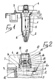
- the pump according to the invention is composed of a cylindrical body 1 defining a cylindrical chamber 2 termed rotor chamber, perpendicularly associated with a plate 3 which is completed by a volute, not illustrated in the figure, determining a chamber within which there is contained an impeller 4 with symmetrical configuration, since it has to operate in both directions of rotation.
- the chamber 2 contains a permanent magnet rotor 5 rigidly associated with a motor shaft 6 frontally supported by a perforated sector 7 and more internally by a second perforated cylindrical body 8.
- the perforated sector 7 is composed of an external cylindrical body 9 associated by means of a deformable circular crown 10 with a central sleeve 11 provided with a hole through which there passes the motor shaft.
- the outer wall of said cylindrical body 7 has a knurled surface 12 adapted to engage in an equivalent knurling present in the inner wall of the rotor chamber 2.
- the deformability of the circular crown 10 and of the cylindrical body 8, on which the motor shaft 6 is supported, allows a self-alignment of the supporting points.
- a metallic cylindrical body 14 provided with a frontal non-axial tab 15, the entire assembly being contained in an axial cavity of the impeller 4 which comprises a first cylindrical section 16 extending with a deeper toroidal cavity 17 which extends for an angle smaller than 360 degrees.
- the front tab 15 of the cylindrical body 14 has a much smaller angular extension than the toroidal cavity 17 within which it is contained.
- Said metallic cylindrical body 14 also has a groove 18 within which an O-Ring 19 is inserted which interferes with the cylindrical region 15 of the cavity of the impeller.
- a locking disk 20 elastically locked on the inner wall of the cavity of the impeller 4 so as to lock the cylindrical body 14 though allowing the free rotation of the impeller 4 with respect to the motor shaft 6.
- a viscous liquid such as for example an oil or a grease which dampens the motion of the tab 15 within the toroidal cavity 17 avoiding noise in the interference between the tab 15 and the sector 21 which interrupts the continuity of the toroidal cavity 17.
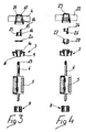
- Figure 4 illustrates a variated aspect of the impeller/motor shaft coupling.
- the impeller 22 has an inner cylindrical cavity 23 wherein there is contained a cylindrical metallic body 24 associated with the motor shaft 25 and provided with a non-axial frontal tab 26.
- the tab 26 inserts in a toroidal chamber with an extension smaller than 360 degrees, indicated at 27 and provided in a cylindrical body of plastic material which inserts, locking itself, into the chamber 23 of the impeller 22.
- the perforated sector 7 provides a complete separation between the rotor chamber and and the impeller chamber.
- the impeller is associated with the motor shaft so that it is initially practically free in at least one direction of rotation.
- the motor which can start in any one of the two directions, starts in the direction of nil resistance and in a first angle of rotation, smaller than 360 degrees, does not determine the actuation of the impeller.
- the actuation of the impeller occurs when the tab which is free to move within the toroidal cavity does not interfere with the inner sector of said cavity.
- the cavity contains a viscous fluid which acts as dampener for the motion of the tab and eliminates the noise of the contact between said tab and the inner sector of the toroidal cavity.
- the materials may also be chosen in any way according to the requirements and to the dimensions of the pump.
Landscapes
- Engineering & Computer Science (AREA)
- Mechanical Engineering (AREA)
- General Engineering & Computer Science (AREA)
- Water Supply & Treatment (AREA)
- Textile Engineering (AREA)
- Structures Of Non-Positive Displacement Pumps (AREA)
- Centrifugal Separators (AREA)
- Filters For Electric Vacuum Cleaners (AREA)
- Jet Pumps And Other Pumps (AREA)
Claims (5)
- Kreiselpumpe für elektrische Haushaltsgeräte, wie Waschmaschinen, Geschirrspülmaschinen und ähnliches, enthaltend ein Pumpengehäuse (1) und eine Volute, die einen wasserdichten Behälter bildet, enthaltend einen Permanentmagnet-Rotor (5) mit einer Welle (6) und ein Flügelrad (4;22), die jeweils in einer ersten (2) und in einer zweiten Kammer angeordnet sind, wobei die erste und zweite Kammer durch einen durchbrochenen Abschnitt (7) voneinander getrennt sind, wobei die Welle (6) durch den durchbrochenen Abschnitt (7) hindurchgeführt ist und mit dem Flügelrad (4;22) durch einen Zapfen (15;26) umfassende Verbindungsmittel verbunden ist, wobei der Zapfen in einem ringförmigen Hohlraum (17;27) des Flügelrades (4;22) enthalten ist, und wobei die Verbindungsmittel einen zweiten zylindrischen Körper (14;24) umfassen, der mit dem sich aus der Rotorkammer 2 erstreckenden Ende 13 der Welle 6 verbunden ist, wobei der zylindrische Körper (14;24) stirnseitig den nicht axial angeordneten Zapfen (15;26) aufweist, der sich über einen kleineren Winkel von ungefähr 90° erstreckt, dadurch gekennzeichnet, daß das Flügelrad (4;22) einen axialen Hohlraum aufweist, der einen im wesentlichen zylindrischen ersten Teil (16;23) und einen zweiten, den ringförmigen Hohlraum (17;22), bildenden Teil aufweist, wobei sich der ringförmige Hohlraum (17;27) über weniger als 360° und mehr als die winkelmäßige Ausdehnung des Zapfens (15;26) des zweiten zylindrischen Körpers (14;24) erstreckt und wobei der Zapfen (15;26) des zylindrischen Körpers (14;24) innerhalb des ringförmigen Hohlraums (17;27) des Flügelrades (4;22) solange frei beweglich ist, bis er mit dem Abschnitt in Berührung kommt, der die Ausdehnung des ringförmigen Hohlraums unterbricht, wobei abgedichtet innerhalb des ringförmigen Hohlraums (17;27) des Flügelrades (4;22) eine viskose Flüssigkeit zur Dämpfung und Absorption von Klopfen und Geräuschen vorgesehen.
- Kreiselpumpe nach Anspruch 1, dadurch gekennzeichnet, daß der durchbrochene Abschnitt (7) einen äußeren zylindrischen Körper (9) enthält, der abgedichtet in die Rotorkammer (2) eingepaßt ist und durch eine deformierbare, kreisförmige Krone (10) mit einer zentralen Hülse (11) verbunden ist, die ein axiales Loch zur Aufnahme der Welle (6) aufweist und ihre Rotation erlaubt.
- Kreiselpumpe nach Anspruch 2, dadurch gekennzeichnet, daß der durchbrochene Abschnitt (7) eine äußere, gerändelte Oberfläche (12) aufweist, die zum Eingriff mit einer entsprechenden an der inneren Wandung der Rotorkammer (2) vorgesehenen Rändelung zusammenwirkt.
- Kreiselpumpe nach Anspruch 1, dadurch gekennzeichnet, daß im innersten Teil der Rotorkammer (2) ein zweiter zylindrischer Körper (8) vorgesehen ist, der mittels einer deformierbaren, kreisförmigen Krone mit einer durchbrochenen Hülse verbunden ist, und der axial angeordnet ist und den zweiten Lager und Rotationspunkt der Motorwelle (6) bildet.
- Kreiselpumpe nach einem der vorhergehenden Ansprüche, dadurch gekennzeichnet, daß der zweite, mit der Motorwelle (6) verbundene zylindrische Körper (14) eine peripher angeordnete Nut (18) aufweist, die zur teilweisen Aufnahme eines O-Rings (19) angepaßt ist, wobei der O-Ring elastisch mit der inneren Wandung des Hohlraums des Flügelrads (4) im Bereich des zylindrischen Abschnitts (16) zusammenwirkt.
Priority Applications (1)
| Application Number | Priority Date | Filing Date | Title |
|---|---|---|---|
| AT88106126T ATE95892T1 (de) | 1987-04-22 | 1988-04-18 | Kreiselpumpe fuer elektrische haushaltsgeraete, wie waschmaschinen, geschirrspuelmaschinen und aehnliches. |
Applications Claiming Priority (2)
| Application Number | Priority Date | Filing Date | Title |
|---|---|---|---|
| IT4158587 | 1987-04-22 | ||
| IT41585/87A IT1218569B (it) | 1987-04-22 | 1987-04-22 | Pompa centrifiga perfezionata per lavatrici, lavastoviglie ed elettrodomestici in genre |
Publications (3)
| Publication Number | Publication Date |
|---|---|
| EP0287984A2 EP0287984A2 (de) | 1988-10-26 |
| EP0287984A3 EP0287984A3 (en) | 1990-05-23 |
| EP0287984B1 true EP0287984B1 (de) | 1993-10-13 |
Family
ID=11251588
Family Applications (1)
| Application Number | Title | Priority Date | Filing Date |
|---|---|---|---|
| EP88106126A Expired - Lifetime EP0287984B1 (de) | 1987-04-22 | 1988-04-18 | Kreiselpumpe für elektrische Haushaltsgeräte, wie Waschmaschinen, Geschirrspülmaschinen und ähnliches |
Country Status (6)
| Country | Link |
|---|---|
| US (1) | US4861240A (de) |
| EP (1) | EP0287984B1 (de) |
| AT (1) | ATE95892T1 (de) |
| DE (1) | DE3884845T2 (de) |
| ES (1) | ES2045000T3 (de) |
| IT (1) | IT1218569B (de) |
Cited By (6)
| Publication number | Priority date | Publication date | Assignee | Title |
|---|---|---|---|---|
| US6007308A (en) * | 1997-07-02 | 1999-12-28 | Johnson Electric S.A. | Coupling device for a pump impeller |
| DE102006045781A1 (de) * | 2006-09-26 | 2008-04-03 | Hanning Elektro-Werke Gmbh & Co. Kg | Antriebseinheit für eine Pumpe, insbesondere Zirkulationspumpe oder Entleerungspumpe |
| DE102006046247A1 (de) * | 2006-09-28 | 2008-04-10 | Hanning Elektro-Werke Gmbh & Co. Kg | Antriebseinrichtung, insbesondere für eine Pumpe |
| EP2248935A1 (de) | 2009-05-04 | 2010-11-10 | Coprecitec, S.L. | Haushaltswasch- oder Spülmaschine und Steuerung hierfür |
| US8057199B2 (en) | 2006-01-26 | 2011-11-15 | Jiangmen Idear Hanyu Electrical | Centrifugal drainage pump with shock absorbing coupling arrangment |
| EP2606803A1 (de) | 2011-12-20 | 2013-06-26 | Coprececitec, S.L. | Verfahren zur Steuerung für ein Wasch-Haushaltsgeräts, und Wasch-Haushaltsgerät |
Families Citing this family (29)
| Publication number | Priority date | Publication date | Assignee | Title |
|---|---|---|---|---|
| ITPD20010256A1 (it) * | 2001-10-30 | 2003-04-30 | Askoll Holding Srl | Dispositivo perfezionato di trascinamento fra il rotore di un motore sincrono a magneti permanenti e l'organo operatore. |
| ITPD980058A1 (it) * | 1998-03-19 | 1999-09-19 | Askoll Holding Srl | Dispositivo di trascinamento, con angolo di libera rotazione ampliato fra il motore sincrono a magneti permanenti e l'organo operatore |
| US5132873A (en) * | 1988-09-30 | 1992-07-21 | Microelectronics And Computer Technology Corporation | Diaphragm sealing apparatus |
| DE3914760A1 (de) * | 1989-05-05 | 1990-11-08 | Aweco Kunststofftech Geraete | Geschirrspuelmaschine mit einem sammeltopf und daran angeschlossenen kreisel-motorpumpen |
| ES2019491A6 (es) * | 1989-08-04 | 1991-06-16 | Fagor S Coop Ltda | Mejoras introducidas en bombas para electrodomesticos accionados por motor sincrono. |
| FR2657126A1 (fr) * | 1990-01-16 | 1991-07-19 | Electro Mec Nivernais | Procede de realisation d'une pompe centrifuge a moteur electrique, et motopompe realisee selon ce procede. |
| FR2667653B1 (fr) * | 1990-10-05 | 1995-01-27 | Electro Mec Nivernais | Motopompe centrifuge. |
| FR2676510B1 (fr) * | 1991-05-14 | 1995-01-06 | Electro Mec Nivernais | Motopompe centrifuge silencieuse. |
| SG126666A1 (en) * | 1991-12-20 | 2006-11-29 | Fisher & Paykel Appliances Ltd | Dishwasher |
| ES2053372B1 (es) * | 1992-02-17 | 1997-04-16 | Fagor S Coop | Mejoras introducidas en bombas accionadas por motor sincrono para electrodomesticos. |
| ES2050057T3 (es) * | 1992-03-16 | 1994-05-01 | Siemens Ag | Motor sincronico monofasico. |
| IT1268531B1 (it) * | 1993-09-17 | 1997-03-04 | Sole Spa | Motopompe autosbloccanti |
| ES2162544B1 (es) | 1998-12-31 | 2002-07-01 | Fagor S Coop | Acoplamiento para la transmision de la rotacion en un motor sincrono. |
| US6190279B1 (en) | 1999-06-10 | 2001-02-20 | Richard D. Squires | Power transmission system with a stall prevention feature |
| US6478555B1 (en) * | 1999-06-16 | 2002-11-12 | Lg Electronics, Inc. | Apparatus for controlling noise and vibration for drain pump |
| EP1212534B1 (de) * | 2000-07-06 | 2004-04-28 | Askoll Holding S.r.l. | Unidirektionales laufrad für eine elektrische kreiselpumpe mit einem permanentmagnet synchronmotor |
| ITPN20010005A1 (it) | 2001-01-25 | 2002-07-25 | Sole Spa | Motopompa |
| US6942415B2 (en) * | 2002-02-26 | 2005-09-13 | The Torrington Company | Shaft assembly safety mechanism |
| ES2268240T3 (es) | 2002-09-03 | 2007-03-16 | Emerson Appliance Motors Europe S.R.L. | Bomba centrifuga para aparatos electrodomesticos. |
| ITPN20020096A1 (it) * | 2002-12-10 | 2004-06-11 | Electrolux Home Products Corporatio N N V | Macchina di lavaggio con motore asincrono perfezionato. |
| EP1553681B1 (de) | 2003-12-31 | 2017-03-15 | Askoll Holding S.r.l. | Kupplungsvorrichtung zwischen einem Rotor eines Permanentmagnetsynchronmotors und einem Funktionsteil |
| DE602004005297T2 (de) * | 2004-01-26 | 2007-12-20 | Nidec Shibaura Corp., Obama | Kreiselpumpe für Waschmaschinen |
| EP1578006A2 (de) * | 2004-03-15 | 2005-09-21 | Nidec Shibaura Corporation | Anlaufhilfe für einen Synchronmotor |
| ITTO20050509A1 (it) | 2005-07-25 | 2007-01-26 | Emerson Appliance Motors Europe | Sistema e procedimento di controllo per un motore elettrico sincrono, particolarmente per elettrodomesici |
| CA2628450A1 (en) * | 2005-11-04 | 2007-05-10 | Fisher & Paykel Appliances Limited | Integrated washing machine pump |
| KR101237022B1 (ko) * | 2010-05-19 | 2013-02-25 | 주식회사 아모텍 | 완전 방수구조를 갖는 유체 펌프 |
| CN102545466B (zh) * | 2010-11-10 | 2015-11-25 | 德昌电机(深圳)有限公司 | 电机装置 |
| DE102013007624A1 (de) * | 2013-05-02 | 2014-11-06 | Wilo Se | Motorenkreiselpumpe mit einem Lagerträger |
| US9752583B2 (en) * | 2014-10-07 | 2017-09-05 | Haier Us Appliance Solutions, Inc. | Pump assembly for appliance |
Family Cites Families (4)
| Publication number | Priority date | Publication date | Assignee | Title |
|---|---|---|---|---|
| IT7822014U1 (it) * | 1978-06-02 | 1979-12-02 | Askoll Srl | Pompa centrifuga per piccole portate, particolarmente per ottenere la circolazione dell'acqua negli acquari e simili. |
| FR2466644A1 (fr) * | 1979-10-04 | 1981-04-10 | Dba | Pompe compacte actionnee par moteur electrique perfectionnements aux dispositifs selecteurs de programmes pour les recepteurs radio-electriques |
| US4703840A (en) * | 1984-05-29 | 1987-11-03 | Eaton Corporation | Torsion damping mechanism |
| DE3683962D1 (de) * | 1985-07-01 | 1992-04-02 | Easthorpe Investments Ltd | Zentrifugalpumpe. |
-
1987
- 1987-04-22 IT IT41585/87A patent/IT1218569B/it active
-
1988
- 1988-04-18 DE DE88106126T patent/DE3884845T2/de not_active Expired - Lifetime
- 1988-04-18 AT AT88106126T patent/ATE95892T1/de active
- 1988-04-18 ES ES88106126T patent/ES2045000T3/es not_active Expired - Lifetime
- 1988-04-18 EP EP88106126A patent/EP0287984B1/de not_active Expired - Lifetime
- 1988-04-19 US US07/183,208 patent/US4861240A/en not_active Expired - Lifetime
Cited By (9)
| Publication number | Priority date | Publication date | Assignee | Title |
|---|---|---|---|---|
| US6007308A (en) * | 1997-07-02 | 1999-12-28 | Johnson Electric S.A. | Coupling device for a pump impeller |
| US8057199B2 (en) | 2006-01-26 | 2011-11-15 | Jiangmen Idear Hanyu Electrical | Centrifugal drainage pump with shock absorbing coupling arrangment |
| DE102006045781A1 (de) * | 2006-09-26 | 2008-04-03 | Hanning Elektro-Werke Gmbh & Co. Kg | Antriebseinheit für eine Pumpe, insbesondere Zirkulationspumpe oder Entleerungspumpe |
| DE102006046247A1 (de) * | 2006-09-28 | 2008-04-10 | Hanning Elektro-Werke Gmbh & Co. Kg | Antriebseinrichtung, insbesondere für eine Pumpe |
| DE202006020761U1 (de) | 2006-09-28 | 2010-05-20 | Hanning Elektro-Werke Gmbh & Co. Kg | Antriebsvorrichtung, insbesondere für eine Pumpe |
| EP2248935A1 (de) | 2009-05-04 | 2010-11-10 | Coprecitec, S.L. | Haushaltswasch- oder Spülmaschine und Steuerung hierfür |
| US8332980B2 (en) | 2009-05-04 | 2012-12-18 | Coprecitec, S.L. | Washing household appliance and control method thereof |
| EP2606803A1 (de) | 2011-12-20 | 2013-06-26 | Coprececitec, S.L. | Verfahren zur Steuerung für ein Wasch-Haushaltsgeräts, und Wasch-Haushaltsgerät |
| US9181952B2 (en) | 2011-12-20 | 2015-11-10 | Coprecitec, S.L. | Washing appliance and control method thereof |
Also Published As
| Publication number | Publication date |
|---|---|
| EP0287984A2 (de) | 1988-10-26 |
| IT1218569B (it) | 1990-04-19 |
| EP0287984A3 (en) | 1990-05-23 |
| DE3884845D1 (de) | 1993-11-18 |
| US4861240A (en) | 1989-08-29 |
| ATE95892T1 (de) | 1993-10-15 |
| ES2045000T3 (es) | 1994-01-16 |
| DE3884845T2 (de) | 1994-02-03 |
| IT8741585A0 (it) | 1987-04-22 |
Similar Documents
| Publication | Publication Date | Title |
|---|---|---|
| US4861240A (en) | Centrifugal pump for electric household appliances such as washing machines, dishwashers and the like | |
| EP0207430B1 (de) | Zentrifugalpumpe | |
| US4955791A (en) | Small size fan | |
| EP0983630B1 (de) | Einheit zum bewegungsübertragen zwischen dem rotor eines dauermagnetsynchronmotors und einem arbeitsteil, mit erhöhtem freien umdrehungswinkel | |
| GB2217784A (en) | Bearing arrangement for axial fan | |
| KR100531536B1 (ko) | 세탁기 | |
| JPH08242565A (ja) | 永久磁石同期電動機のロータのための改良された始動装置およびそれを備える遠心ポンプ | |
| EP3135921A1 (de) | Flüssigkeitspumpe, motor und wellenbuchseneinheit dafür | |
| US4783173A (en) | Combined washer and collar for supporting a motor | |
| EP0610826A2 (de) | Verbesserte Kreiselpumpe | |
| US5174318A (en) | Motor mount for domestic dishwasher | |
| US6217452B1 (en) | Direction-dependent driving coupling between the rotor of a permanent-magnet synchronous motor and the working part | |
| US3256829A (en) | Pump and motor assembly | |
| KR920021791A (ko) | 가전제품 | |
| RU2006119913A (ru) | Устройство вовлечения жидкости для центробежного ротора | |
| EP1571252A1 (de) | Elektrisch angetriebene Pumpe für Waschmaschine o.ä. | |
| US6887048B2 (en) | Liquid pump and sealing mechanism | |
| EP0481410A2 (de) | Vorrichtung zur Kupplung von Flügelrad an Rotor | |
| US6046522A (en) | Single direction single phase synchronous motor | |
| EP0365963A2 (de) | Schwingungsdämpfendes, selbstzentrierendes Rotorlager | |
| KR102117786B1 (ko) | 팬 모터 | |
| US2888283A (en) | Rotary shaft joint assembly | |
| KR200149129Y1 (ko) | 펌프용 임펠러와 메카니컬 시일의 모터 회전축 고정구조 | |
| EP0217235A1 (de) | Elektrische Pumpe mit magnetischer Kupplung | |
| KR200239397Y1 (ko) | 선풍기 회전용 모터의 주축보강구조 |
Legal Events
| Date | Code | Title | Description |
|---|---|---|---|
| PUAI | Public reference made under article 153(3) epc to a published international application that has entered the european phase |
Free format text: ORIGINAL CODE: 0009012 |
|
| AK | Designated contracting states |
Kind code of ref document: A2 Designated state(s): AT BE CH DE ES FR GB GR IT LI LU NL SE |
|
| PUAL | Search report despatched |
Free format text: ORIGINAL CODE: 0009013 |
|
| AK | Designated contracting states |
Kind code of ref document: A3 Designated state(s): AT BE CH DE ES FR GB GR IT LI LU NL SE |
|
| 17P | Request for examination filed |
Effective date: 19900517 |
|
| 17Q | First examination report despatched |
Effective date: 19910812 |
|
| GRAA | (expected) grant |
Free format text: ORIGINAL CODE: 0009210 |
|
| AK | Designated contracting states |
Kind code of ref document: B1 Designated state(s): AT BE CH DE ES FR GB GR IT LI LU NL SE |
|
| PG25 | Lapsed in a contracting state [announced via postgrant information from national office to epo] |
Ref country code: AT Effective date: 19931013 Ref country code: CH Effective date: 19931013 Ref country code: BE Effective date: 19931013 Ref country code: NL Effective date: 19931013 Ref country code: LI Effective date: 19931013 Ref country code: SE Effective date: 19931013 Ref country code: GR Free format text: LAPSE BECAUSE OF FAILURE TO SUBMIT A TRANSLATION OF THE DESCRIPTION OR TO PAY THE FEE WITHIN THE PRESCRIBED TIME-LIMIT Effective date: 19931013 |
|
| REF | Corresponds to: |
Ref document number: 95892 Country of ref document: AT Date of ref document: 19931015 Kind code of ref document: T |
|
| ET | Fr: translation filed | ||
| REF | Corresponds to: |
Ref document number: 3884845 Country of ref document: DE Date of ref document: 19931118 |
|
| ITF | It: translation for a ep patent filed | ||
| REG | Reference to a national code |
Ref country code: ES Ref legal event code: FG2A Ref document number: 2045000 Country of ref document: ES Kind code of ref document: T3 |
|
| REG | Reference to a national code |
Ref country code: CH Ref legal event code: PL |
|
| NLV1 | Nl: lapsed or annulled due to failure to fulfill the requirements of art. 29p and 29m of the patents act | ||
| PG25 | Lapsed in a contracting state [announced via postgrant information from national office to epo] |
Ref country code: LU Free format text: LAPSE BECAUSE OF NON-PAYMENT OF DUE FEES Effective date: 19940430 |
|
| PLBE | No opposition filed within time limit |
Free format text: ORIGINAL CODE: 0009261 |
|
| STAA | Information on the status of an ep patent application or granted ep patent |
Free format text: STATUS: NO OPPOSITION FILED WITHIN TIME LIMIT |
|
| 26N | No opposition filed | ||
| REG | Reference to a national code |
Ref country code: GB Ref legal event code: IF02 |
|
| PGFP | Annual fee paid to national office [announced via postgrant information from national office to epo] |
Ref country code: DE Payment date: 20070327 Year of fee payment: 20 |
|
| PGFP | Annual fee paid to national office [announced via postgrant information from national office to epo] |
Ref country code: GB Payment date: 20070328 Year of fee payment: 20 |
|
| PGFP | Annual fee paid to national office [announced via postgrant information from national office to epo] |
Ref country code: ES Payment date: 20070416 Year of fee payment: 20 |
|
| PGFP | Annual fee paid to national office [announced via postgrant information from national office to epo] |
Ref country code: IT Payment date: 20070608 Year of fee payment: 20 |
|
| PGFP | Annual fee paid to national office [announced via postgrant information from national office to epo] |
Ref country code: FR Payment date: 20070426 Year of fee payment: 20 |
|
| REG | Reference to a national code |
Ref country code: GB Ref legal event code: PE20 Expiry date: 20080417 |
|
| REG | Reference to a national code |
Ref country code: ES Ref legal event code: FD2A Effective date: 20080419 |
|
| PG25 | Lapsed in a contracting state [announced via postgrant information from national office to epo] |
Ref country code: ES Free format text: LAPSE BECAUSE OF EXPIRATION OF PROTECTION Effective date: 20080419 |
|
| PG25 | Lapsed in a contracting state [announced via postgrant information from national office to epo] |
Ref country code: GB Free format text: LAPSE BECAUSE OF EXPIRATION OF PROTECTION Effective date: 20080417 |