EP0288023B1 - Befestigungselement - Google Patents
Befestigungselement Download PDFInfo
- Publication number
- EP0288023B1 EP0288023B1 EP88106279A EP88106279A EP0288023B1 EP 0288023 B1 EP0288023 B1 EP 0288023B1 EP 88106279 A EP88106279 A EP 88106279A EP 88106279 A EP88106279 A EP 88106279A EP 0288023 B1 EP0288023 B1 EP 0288023B1
- Authority
- EP
- European Patent Office
- Prior art keywords
- screw
- ribs
- threaded sleeve
- moulded
- securing element
- Prior art date
- Legal status (The legal status is an assumption and is not a legal conclusion. Google has not performed a legal analysis and makes no representation as to the accuracy of the status listed.)
- Expired - Lifetime
Links
- 239000004033 plastic Substances 0.000 claims abstract description 23
- 229920003023 plastic Polymers 0.000 claims abstract description 23
- 239000011810 insulating material Substances 0.000 claims abstract description 17
- 239000000463 material Substances 0.000 claims 5
- 239000002184 metal Substances 0.000 abstract description 9
- 239000011888 foil Substances 0.000 abstract 1
- 239000012774 insulation material Substances 0.000 description 5
- 238000005553 drilling Methods 0.000 description 3
- 239000002985 plastic film Substances 0.000 description 3
- 229920006255 plastic film Polymers 0.000 description 3
- 210000000078 claw Anatomy 0.000 description 2
- 238000009434 installation Methods 0.000 description 1
- 238000000465 moulding Methods 0.000 description 1
- 238000010079 rubber tapping Methods 0.000 description 1
- 239000000758 substrate Substances 0.000 description 1
Images


Classifications
-
- F—MECHANICAL ENGINEERING; LIGHTING; HEATING; WEAPONS; BLASTING
- F16—ENGINEERING ELEMENTS AND UNITS; GENERAL MEASURES FOR PRODUCING AND MAINTAINING EFFECTIVE FUNCTIONING OF MACHINES OR INSTALLATIONS; THERMAL INSULATION IN GENERAL
- F16B—DEVICES FOR FASTENING OR SECURING CONSTRUCTIONAL ELEMENTS OR MACHINE PARTS TOGETHER, e.g. NAILS, BOLTS, CIRCLIPS, CLAMPS, CLIPS OR WEDGES; JOINTS OR JOINTING
- F16B13/00—Dowels or other devices fastened in walls or the like by inserting them in holes made therein for that purpose
- F16B13/04—Dowels or other devices fastened in walls or the like by inserting them in holes made therein for that purpose with parts gripping in the hole or behind the reverse side of the wall after inserting from the front
- F16B13/06—Dowels or other devices fastened in walls or the like by inserting them in holes made therein for that purpose with parts gripping in the hole or behind the reverse side of the wall after inserting from the front combined with expanding sleeve
- F16B13/061—Dowels or other devices fastened in walls or the like by inserting them in holes made therein for that purpose with parts gripping in the hole or behind the reverse side of the wall after inserting from the front combined with expanding sleeve of the buckling type
-
- E—FIXED CONSTRUCTIONS
- E04—BUILDING
- E04D—ROOF COVERINGS; SKY-LIGHTS; GUTTERS; ROOF-WORKING TOOLS
- E04D3/00—Roof covering by making use of flat or curved slabs or stiff sheets
- E04D3/36—Connecting; Fastening
- E04D3/3601—Connecting; Fastening of roof covering supported by the roof structure with interposition of a insulating layer
- E04D3/3603—Connecting; Fastening of roof covering supported by the roof structure with interposition of a insulating layer the fastening means being screws or nails
-
- E—FIXED CONSTRUCTIONS
- E04—BUILDING
- E04D—ROOF COVERINGS; SKY-LIGHTS; GUTTERS; ROOF-WORKING TOOLS
- E04D5/00—Roof covering by making use of flexible material, e.g. supplied in roll form
- E04D5/14—Fastening means therefor
- E04D5/144—Mechanical fastening means
- E04D5/145—Discrete fastening means, e.g. discs or clips
-
- F—MECHANICAL ENGINEERING; LIGHTING; HEATING; WEAPONS; BLASTING
- F16—ENGINEERING ELEMENTS AND UNITS; GENERAL MEASURES FOR PRODUCING AND MAINTAINING EFFECTIVE FUNCTIONING OF MACHINES OR INSTALLATIONS; THERMAL INSULATION IN GENERAL
- F16B—DEVICES FOR FASTENING OR SECURING CONSTRUCTIONAL ELEMENTS OR MACHINE PARTS TOGETHER, e.g. NAILS, BOLTS, CIRCLIPS, CLAMPS, CLIPS OR WEDGES; JOINTS OR JOINTING
- F16B13/00—Dowels or other devices fastened in walls or the like by inserting them in holes made therein for that purpose
Definitions
- the invention relates to a fastening element for an elastic, resilient thermal insulation material, consisting of a holding washer made of plastic with a tubular recess which can penetrate into the insulating material and a screw which engages through the bottom of the recess with its head, with axially parallel webs made of plastic continuing the tubular recess are molded.
- Such a fastening element for an elastic, resilient thermal insulation material is known from US Pat. No. 4,452,023, consisting of a holding washer made of plastic with a tubular recess which can be penetrated into the insulating material and a screw which engages through the bottom of the recess and lies with its head, which interacts with a dowel element, with the continuation of tubular recess axially parallel plastic webs are formed.
- the screw engages in a dowel element in the subsurface and pulls the entire fastening element together, compressing the thermal insulation material, causing the plastic webs to buckle.
- the fact that the heat insulating material is compressed in the region of the holding disk and forms a depression proves to be disadvantageous.
- Such attachment also requires the attachment of a dowel element in the subsurface under the heat insulation material.
- the object of the invention is to design a fastening element of the type mentioned so that its use for an elastic, resilient thermal insulation material is also possible when a fastening base, in which a screw could engage, is not present.
- the fastening element can brace the structure or be fastened to a plate arranged under the insulating material, for example a sheet metal.
- the plastic webs are integrally formed on the front end of the tubular recess, wherein two opposite webs are expediently provided in continuation of the tubular recess and the webs are profiled transversely to the axial direction in order to achieve a defined bulging or buckling.
- the plastic webs have sufficient strength or rigidity so that the fastening element can be pressed into and through the insulating material in a known manner.
- the fastening element is placed with its front shoulder on a base, for example a sheet metal, the molded webs protrude through a hole in the base into the free space arranged below.
- the diameter of the threaded sleeve that connects the webs and the outer distance between the two webs are expediently chosen to be smaller than the outer diameter of the tubular recess.
- Such a fastening element according to the invention can be used in any position on an insulating material structure, for example a corresponding roof structure with an outer film, insulating material arranged underneath and, in turn, sheet metal provided underneath.
- FIGS. 1 and 2 A tubular recess 12 is formed in the center downward on a holding disk 11 made of plastic of the fastening element denoted by the number 1, which is approximately rectangular in plan.
- the inner bore has the number 13.
- the bottom of this recess 12 is equipped with a smaller diameter bore 15.
- the bore 13 merges into the bore 15 with a conical surface 14.
- two opposing webs 17 are formed on the inside, which are connected to one another at the other end by the threaded sleeve 19. Due to the offset molding of the plastic webs 17, the shoulder 16 is formed on the outside. The webs 17 are profiled on the outside transversely to the axial direction with claw elements 18.
- the screw denoted by the number 2 is inserted from the outside, accessible with a screwdriver, and its head 21 rests against the inside of the conical surface 14 with its screw shaft 22 is guided through the bore 15 and engages with its shaft end in the internal thread of the threaded sleeve 19.
- the screw shaft can cut into a corresponding inner surface of a plastic sleeve 19 by means of a self-tapping screw.
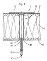
- FIG. 3 shows the manner in which such a fastening element according to FIGS. 1 and 2 is introduced into an insulating structure, for example a roof.
- a hole is first made in the insulating structure, preferably with a slightly smaller diameter than the outer diameter of the tubular recess 12 in the region of the upper plastic film 3 and the insulating material 4 arranged underneath.
- the tubular recess 12 rests on the section 16 with the number 5 indicated sheet metal plate 5.
- the threaded sleeve 19 rises on the shaft 22 upwards.
- the plastics 17 are bulged or buckled outwards. This buckling is favored by the corresponding profiling 18 of the webs 17.
- the bulging or buckling webs 17 lie against the sheet metal plate 5 from the underside, so that the fastening element 1 with the holding plate 11 and the ones lying against the outside Bridges 17 braced on the entire structure.
- the plastic film 3 and the insulating material arranged underneath are thus held on the sheet metal plate 5, which is fastened to a substrate with other fastening means.
Landscapes
- Engineering & Computer Science (AREA)
- Mechanical Engineering (AREA)
- General Engineering & Computer Science (AREA)
- Architecture (AREA)
- Civil Engineering (AREA)
- Structural Engineering (AREA)
- Connection Of Plates (AREA)
- Dowels (AREA)
- Building Environments (AREA)
- Surgical Instruments (AREA)
- Crystals, And After-Treatments Of Crystals (AREA)
- Piezo-Electric Or Mechanical Vibrators, Or Delay Or Filter Circuits (AREA)
- Joining Of Building Structures In Genera (AREA)
Description
- Die Erfindung betrifft ein Befestigungselement für ein elastisches nachgiebiges Wärmeisoliermaterial, bestehend aus einer Haltescheibe aus Kunststoff mit einer in das Isoliermaterial eindringbaren rohrförmigen Vertiefung und einer durch den Boden der Vertiefung hindurchgreifenden, mit ihrem Kopf anliegenden Schraube, wobei in Fortsetzung der rohrförmigen Vertiefung achsparallele Stege aus Kunststoff angeformt sind.
- Es ist ein solches Befestigungselement für ein elastisches nachgiebiges Wärmeisoliermaterial bekannt aus der US-A-4 452 023, bestehend aus einer Haltescheibe aus Kunststoff mit einer in das Isoliermaterial eindringbaren rohrförmigen Vertiefung und einer durch den Boden der Vertiefung hindurchgreifenden, mit ihrem Kopf anliegenden Schraube, die mit einem Dübelelement zusammenwirkt, wobei in Fortsetzung der rohrförmigen Vertiefung achsparallele Stege aus Kunststoff angeformt sind. Die Schraube greift beim Anziehen in ein Dübelelement im Untergrund ein und zieht das gesamte Befestigungselement unter Zusammendrückung des Wärmeisoliermaterials an, wobei die Kunststoffstege ausknicken. Nachteilig erweist sich dabei die Tatsache, daß das Wärmeisoliermaterial im Bereich der Haltescheibe zusammengedrückt wird und eine Vertiefung bildet. Eine solche Befestigung setzt außerdem die Anbringung eines Dübelelementes im Untergrund unter dem Wärmeisoliermaterial voraus.
- Für den Fall, daß eine Einschraubung in einen Untergrund und damit der Einsatz eines Dübelelementes nicht möglich ist, also beispielsweise wenn unter dem Isoliermaterial ein Luftzwischenraum vorgesehen ist, läßt sich ein solches bekanntes Befestigungselement nicht verwenden.
- Die Aufgabe der Erfindung besteht darin, ein Befestigungselement der genannten Art so zu gestalten, daß dessen Einsatz für ein elastisches nachgiebiges Wärmeisoliermaterial auch dann möglich ist, wenn ein Befestigungsuntergrund, in den eine Schraube eingreifen könnte, nicht vorhanden ist.
- Gelöst wird die Erfindungsaufgabe mit einem Befestigungselement mit sämtlichen Merkmalen des Anspruches 1.
- Bei entsprechender Verdrehung der Schraube des Befestigungselementes steigt die Gewindehülse auf der Schraubspindel in Richtung des Schraubenkopfes, die zwischen Gewindehülse und rohrförmiger Vertiefung angeformten Stege knicken bzw. beulen sich nach außen aus und kommen zur Anlage an der Unterseite des Unterbaues. Auf diese Weise kann das Befestigungselement den Aufbau verspannen bzw. an einer unter dem Isoliermaterial angeordneten Platte, beispielsweise einem Blech, befestigt werden.
- Nach einer bevorzugten Ausführungsart der Erfindung sind die Kunststoffstege am Stirnende der rohrförmigen Vertiefung nach innen abgesetzt angeformt, wobei zweckmäßigerweise in Fortsetzung der rohrförmigen Vertiefung zwei sich gegenüberliegende Stege vorgesehen und die Stege quer zur Achsrichtung profiliert sind, um ein definiertes Ausbeulen bzw. Ausknicken zu erreichen. Die Kunststoffstege haben eine ausreichende Festigkeit bzw. Steifigkeit, so daß in bekannter Weise das Befestigungselement in und durch das Isoliermaterial gedrückt werden kann. Das Befestigungselement setzt mit seinem stirnseitigen Absatz auf einer Unterlage, beispielsweise einem Blech, auf, die angeformten Stege ragen durch eine Bohrung in der Unterlage in den darunter angeordneten freien Raum. Der Durchmesser der Gewindehülse, der die Stege verbindet und der äußeren Abstand der beiden Stege sind zweckmäßigerweise kleiner gewählt als der Außendurchmesser der rohrförmigen Vertiefung.
- Ein solches erfindungsgemäßes Befestigungselement läßt sich in jeder Lage an einem Isoliermaterialaufbau, beispielsweise einem entsprechenden Dachaufbau mit Außenfolie, darunter angeordnetem Isoliermaterial und wiederum darunter vorgesehenem Blech einsetzen.
- Anhand eines abgebildeten Ausführungsbeispiels wird die Erfindung im folgenden näher erläutert. Es zeigen:
- Fig. 1
- eine vergrößerte teilweise geschnittene Ansicht eines Befestigungselementes,
- Fig. 2
- eine weitere Seitenansicht auf das Element in Fig. 1.
- Fig. 3
- eine Einbausituation im Schnitt durch einen wärmeisolierenden Dachaufbau nach dem Einbringen des Befestigungselementes
und - Fig. 4
- eine Teildarstellung der in Fig. 3 dargestellten Situation während des Festspannens des Befestigungselementes.
- Zunächst wird auf die Figuren 1 und 2 Bezug genommen. An einer im Grundriß etwa rechteckigen Haltescheibe 11 aus Kunststoff des mit der Ziffer 1 bezeichneten Befestigungselementes ist mittig nach unten gerichtet eine rohrförmige Vertiefung 12 angeformt. Die Innenbohrung trägt die Ziffer 13. Der Boden dieser Vertiefung 12 ist mit einer durchmesserkleineren Bohrung 15 ausgestattet. Die Bohrung 13 geht mit einer konischen Fläche 14 in die Bohrung 15 über.
- In Fortsetzung der rohrförmigen Vertiefung 12 sind nach innen abgesetzt zwei sich gegenüberliegende Stege 17 angeformt, die am anderen Ende durch die Gewindehülse 19 miteinander verbunden sind. Durch die abgesetzte Anformung der Kunststoffstege 17 ist der Absatz 16 außen gebildet. Die Stege 17 sind außen quer zur Achsrichtung mit Verkrallungselementen 18 profiliert.
- Durch die Bohrung 13 in der rohrförmigen Vertiefung 12 ist von außen die mit einem Schraubendreher zugänglich die mit der Ziffer 2 bezeichnete Schraube eingeführt, die mit ihrem Kopf 21 innen an der konischen Fläche 14 anliegt, mit ihrem Schraubenschaft 22 durch die Bohrung 15 geführt ist und mit ihrem Schaftende in das Innengewinde der Gewindehülse 19 eingreift. Mittels selbstschneidender Schraube kann sich der Schraubenschaft in eine entsprechende Innenfläche einer Kunststoffhülse 19 einschneiden.
- In Fig. 3 ist dargestellt, in welcher Weise ein solches Befestigungselement entsprechend den Figuren 1 und 2 in einen Isolieraufbau, beispielsweise eines Daches, eingebracht wird. Dazu wird zunächst in den Isolieraufbau eine Bohrung eingebracht, vorzugsweise mit einem etwas geringeren Durchmesser als der Außendurchmesser der rohrförmigen Vertiefung 12 im Bereich der oberen Kunststoffolie 3 und des darunter angeordneten Isoliermateriales 4. Die rohrförmige Vertiefung 12 setzt mit ihrem Absatz 16 auf dem mit der Ziffer 5 angedeuteten Blechplatte 5 auf. Durch die Bohrung 51 in dieser Blechplatte 5 ragen die Stege 17 mit der endseitigen verbindenden Kunststoffhülse 19 und der aufgenommenen Schraube 2 hindurch.
- Erfolgt nun eine entsprechende Verdrehung der Schraube 2 durch Einsatz eines entsprechenden Schraubendrehers am Kopf 21, so steigt die Gewindehülse 19 auf dem Schaft 22 nach oben. Dabei werden die Kunststoffe 17 nach außen ausgebeult bzw. ausgeknickt. Begünstigt wird diese Ausknickung durch die entsprechende Profilierung 18 der Stege 17. Die sich ausbeulenden bzw. die ausknickenden Stege 17 legen sich von der Unterseite her an der Blechplatte 5 an, so daß sich das Befestigungselement 1 mit der Halteplatte 11 und den sich nach außen anliegenden Stegen 17 am gesamten Aufbau verspannt. Die Kunststoffolie 3 und das darunter angeordnete Isoliermaterial werden damit an der Blechplatte 5, die mit anderen Befestigungsmitteln an einem Untergrund befestigt ist, gehalten.
- Es besteht auch die Möglichkeit, die durch die Kunststoffgewindehülse 19 hindurchgeführte Schraube auf ihrem freien Ende mit einer Mutter oder Gewindehülse zu versehen. Beim Anziehen der Schraube in entsprechende Richtung wird die Mutter oder die Gewindehülse auf den Schraubenkopf zubewegt. Dabei werden die Kunststoffstege 17 der Kunststoffgewindehülse 19, die in diesem Falle innen auch ohne Gewinde ausgeführt werden kann, ebenfalls nach außen ausgebeult bezw. ausgeknickt.
-
- 1
- Befestigungselement
- 11
- Haltescheibe
- 12
- rohrförmige Vertiefung
- 13
- Bohrung
- 14
- konischer Abschnitt
- 15
- Bohrung
- 16
- Absatz
- 17
- Steg
- 18
- Verkrallungselement
- 19
- Gewindehülse
- 2
- Schraube
- 21
- Kopf
- 22
- Schaft
- 3
- Kunststoffolie
- 4
- lsoliermaterial
- 5
- Blechplatte
- 51
- Bohrung
Claims (6)
- Befestigungselement (1) für ein elastisches nachgiebiges Wärmeisoliermaterial, bestehend aus einer Haltescheibe (11) aus Kunststoff mit einer in das Isoliermaterial eindringbaren rohrförmigen Vertiefung (12) und einer durch den Boden der Vertiefung hindurchgreifenden, mit ihrem Kopf anliegenden Schraube (2), wobei in Fortsetzung der rohrförmigen Vertiefung (12) achsparallele Stege (17) aus Kunststoff angeformt sind, dadurch gekennzeichnet, daß die achsparallelen Stege (17) an ihrem äußeren Ende durch eine angeformte Kunststoffgewindehülse (19) verbunden sind, in die die Schraube (2) eingreift, so daß bei Verdrehung der Schraube (2) die in Richtung des Schraubenkopfes aufsteigende Kunststoffgewindehülse (19) ein Ausknicken und Verkrallen der Stege (17) bewirkt.
- Befestigungselement nach Anspruch 1, dadurch gekennzeichnet, daß die Stege (17) am Stirnende (16) der rohrförmigen Vertiefung (12) nach innen abgesetzt angeformt sind.
- Befestigungselement nach Anspruch 1, dadurch gekennzeichnet, daß in Fortsetzung der rohrförmigen Vertiefung (12) zwei sich gegenüberliegende Stege (17) angeformt sind.
- Befestigungselement nach Anspruch 1, dadurch gekennzeichnet, daß die Stege (17) quer zur Achsrichtung profiliert sind.
- Befestigungselement nach Anspruch 4, dadurch gekennzeichnet, daß die Stege (17, 18) außen mit Verkrallungselementen profiliert sind.
- Befestigungselement nach Anspruch 1, dadurch gekennzeichnet, daß auf eine durch die Kunststoffgewindehülse (19) hindurchgeführte Schraube eine Mutter oder Gewindehülse von außen aufgeschraubt ist.
Priority Applications (1)
| Application Number | Priority Date | Filing Date | Title |
|---|---|---|---|
| AT88106279T ATE68033T1 (de) | 1987-04-24 | 1988-04-20 | Befestigungselement. |
Applications Claiming Priority (2)
| Application Number | Priority Date | Filing Date | Title |
|---|---|---|---|
| DE19873713686 DE3713686A1 (de) | 1987-04-24 | 1987-04-24 | Befestigungselement |
| DE3713686 | 1987-04-24 |
Publications (3)
| Publication Number | Publication Date |
|---|---|
| EP0288023A2 EP0288023A2 (de) | 1988-10-26 |
| EP0288023A3 EP0288023A3 (en) | 1989-02-08 |
| EP0288023B1 true EP0288023B1 (de) | 1991-10-02 |
Family
ID=6326186
Family Applications (1)
| Application Number | Title | Priority Date | Filing Date |
|---|---|---|---|
| EP88106279A Expired - Lifetime EP0288023B1 (de) | 1987-04-24 | 1988-04-20 | Befestigungselement |
Country Status (3)
| Country | Link |
|---|---|
| EP (1) | EP0288023B1 (de) |
| AT (1) | ATE68033T1 (de) |
| DE (2) | DE3713686A1 (de) |
Families Citing this family (10)
| Publication number | Priority date | Publication date | Assignee | Title |
|---|---|---|---|---|
| DE3916515C1 (de) * | 1989-05-20 | 1990-11-08 | Friedr. Trurnit Gmbh, 5990 Altena, De | |
| DE9206380U1 (de) * | 1992-05-12 | 1993-09-09 | Fischerwerke Artur Fischer Gmbh & Co Kg, 72178 Waldachtal | Befestigungselement für Dämmstoffplatten |
| DE4324598A1 (de) * | 1993-07-22 | 1995-01-26 | Fischer Artur Werke Gmbh | Dämmstoffhalter mit einem aufspreizbaren Dübelschaft |
| DE4324597A1 (de) * | 1993-07-22 | 1995-01-26 | Fischer Artur Werke Gmbh | Dämmstoffhalter mit einem aufspreizbaren Dübelschaft und einem Halteteller |
| DE9410723U1 (de) * | 1994-07-02 | 1994-12-22 | Harald Zahn GmbH, 69168 Wiesloch | Trittsicheres Befestigungselement für Dämm- und Dichtungsmaterial auf Flachdächern |
| DE19846204C2 (de) | 1998-10-07 | 2001-08-09 | Sfs Ind Holding Ag Heerbrugg | Befestigungselement sowie Verfahren zum Befestigen von Isolationsbahnen oder -platten auf einem festen Unterbau, insbesondere im Dachbereich von Gebäuden |
| DE10062939A1 (de) * | 2000-12-16 | 2002-07-25 | Zahn Harald Gmbh | Befestigungselement für die mechanische Befestigung von Dämm- und Dichtungsmaterialien auf Flachdächern |
| DE102004052917B3 (de) * | 2004-10-29 | 2005-12-22 | Harald Zahn Gmbh | Befestigungselement |
| DE102005051172B4 (de) | 2004-10-29 | 2021-11-18 | Harald Zahn Gmbh | Befestigungselement für die mechanische Befestigung von Dämm- und Dichtungsmaterialien auf Flachdächern |
| CZ303125B6 (cs) * | 2009-07-31 | 2012-04-18 | Bravoll Spol. S R. O. | Hmoždinka s alternativním zapuštením prítlacného talíre v izolaci a zpusob montáže a montážní prípravek |
Family Cites Families (4)
| Publication number | Priority date | Publication date | Assignee | Title |
|---|---|---|---|---|
| NL128090C (de) * | 1964-06-18 | 1900-01-01 | ||
| FI51728C (fi) * | 1976-03-16 | 1977-03-10 | Jarmo Jaervinen | Kiinnike. |
| FI60278C (fi) * | 1980-10-20 | 1985-07-22 | Rakennusruuvi Oy | Faestdon |
| DE3045986C2 (de) * | 1980-12-05 | 1985-04-04 | Adolf Böhl Schrauben- und Kunststoffwerk GmbH & Co, 5920 Bad Berleburg | Befestigungselement für die Befestigung von wärmeisolierenden Platten |
-
1987
- 1987-04-24 DE DE19873713686 patent/DE3713686A1/de active Granted
-
1988
- 1988-04-20 AT AT88106279T patent/ATE68033T1/de not_active IP Right Cessation
- 1988-04-20 DE DE8888106279T patent/DE3865228D1/de not_active Expired - Fee Related
- 1988-04-20 EP EP88106279A patent/EP0288023B1/de not_active Expired - Lifetime
Also Published As
| Publication number | Publication date |
|---|---|
| ATE68033T1 (de) | 1991-10-15 |
| EP0288023A2 (de) | 1988-10-26 |
| DE3713686C2 (de) | 1991-03-28 |
| EP0288023A3 (en) | 1989-02-08 |
| DE3865228D1 (de) | 1991-11-07 |
| DE3713686A1 (de) | 1988-11-17 |
Similar Documents
| Publication | Publication Date | Title |
|---|---|---|
| EP0302909B1 (de) | Befestigungselement mit einer grossflächigen unterlegscheibe | |
| DE69300650T2 (de) | Druckknopf. | |
| EP0379860B1 (de) | Halteelement aus Kunststoff | |
| DE3825082C2 (de) | ||
| DE69802355T2 (de) | Befestigungsanordnung zum Verbinden eines Teils mit einem zweiten | |
| EP0307647A1 (de) | Unterlegscheibe | |
| EP0288023B1 (de) | Befestigungselement | |
| DE3318800A1 (de) | Befestigungselement fuer bauteile an einer wand | |
| DE102021113281A1 (de) | Toleranzausgleichsvorrichtung | |
| DE2744036C3 (de) | Vorrichtung zum Befestigen einer Dacheindeckungsplatte | |
| EP0211966A1 (de) | Befestigungselement fur Fussmatten | |
| DE3506127C2 (de) | ||
| EP0462058A1 (de) | Befestigungsvorrichtung | |
| DE3703024C2 (de) | ||
| EP0399210B1 (de) | Befestigungselement zur Befestigung von plattenartigem Wärmeisoliermaterial | |
| DE3639748C2 (de) | Schraube zum Befestigen von Fassadenplatten an einer Unterkonstruktion | |
| DE2433669A1 (de) | Vorrichtung zur befestigung lose verlegter dachhaeute | |
| EP1245840B1 (de) | Magazin für Befestigungselemente | |
| EP0978663B1 (de) | Befestigungseinheit zur Befestigung eines Gegenstandes an einem Profilelement mit einem Längsschlitz | |
| DE2946993C2 (de) | ||
| DE3403128A1 (de) | Schraubverbindung | |
| DE3416677C2 (de) | ||
| EP0551873B1 (de) | Kunststoffbefestigungselement zum Aufdrücken auf einen Gewindebolzen | |
| DE19543663C2 (de) | Befestigungselement zur Fixierung einer Wärmedämmplatte oder dergleichen an einer Unterlage | |
| CH445207A (de) | Vorrichtung zur lösbaren Verbindung von zwei Teilen |
Legal Events
| Date | Code | Title | Description |
|---|---|---|---|
| PUAI | Public reference made under article 153(3) epc to a published international application that has entered the european phase |
Free format text: ORIGINAL CODE: 0009012 |
|
| AK | Designated contracting states |
Kind code of ref document: A2 Designated state(s): AT BE CH DE FR GB LI NL SE |
|
| PUAL | Search report despatched |
Free format text: ORIGINAL CODE: 0009013 |
|
| AK | Designated contracting states |
Kind code of ref document: A3 Designated state(s): AT BE CH DE FR GB LI NL SE |
|
| 17P | Request for examination filed |
Effective date: 19890119 |
|
| 17Q | First examination report despatched |
Effective date: 19901213 |
|
| GRAA | (expected) grant |
Free format text: ORIGINAL CODE: 0009210 |
|
| AK | Designated contracting states |
Kind code of ref document: B1 Designated state(s): AT BE CH DE FR GB LI NL SE |
|
| REF | Corresponds to: |
Ref document number: 68033 Country of ref document: AT Date of ref document: 19911015 Kind code of ref document: T |
|
| REF | Corresponds to: |
Ref document number: 3865228 Country of ref document: DE Date of ref document: 19911107 |
|
| GBT | Gb: translation of ep patent filed (gb section 77(6)(a)/1977) | ||
| ET | Fr: translation filed | ||
| PLBE | No opposition filed within time limit |
Free format text: ORIGINAL CODE: 0009261 |
|
| STAA | Information on the status of an ep patent application or granted ep patent |
Free format text: STATUS: NO OPPOSITION FILED WITHIN TIME LIMIT |
|
| 26N | No opposition filed | ||
| PG25 | Lapsed in a contracting state [announced via postgrant information from national office to epo] |
Ref country code: DE Effective date: 19930101 |
|
| EAL | Se: european patent in force in sweden |
Ref document number: 88106279.8 |
|
| PGFP | Annual fee paid to national office [announced via postgrant information from national office to epo] |
Ref country code: AT Payment date: 19970423 Year of fee payment: 10 |
|
| PGFP | Annual fee paid to national office [announced via postgrant information from national office to epo] |
Ref country code: CH Payment date: 19970429 Year of fee payment: 10 |
|
| PG25 | Lapsed in a contracting state [announced via postgrant information from national office to epo] |
Ref country code: AT Free format text: LAPSE BECAUSE OF NON-PAYMENT OF DUE FEES Effective date: 19980420 |
|
| PGFP | Annual fee paid to national office [announced via postgrant information from national office to epo] |
Ref country code: SE Payment date: 19980422 Year of fee payment: 11 Ref country code: BE Payment date: 19980422 Year of fee payment: 11 |
|
| PG25 | Lapsed in a contracting state [announced via postgrant information from national office to epo] |
Ref country code: LI Free format text: LAPSE BECAUSE OF NON-PAYMENT OF DUE FEES Effective date: 19980430 Ref country code: CH Free format text: LAPSE BECAUSE OF NON-PAYMENT OF DUE FEES Effective date: 19980430 |
|
| REG | Reference to a national code |
Ref country code: CH Ref legal event code: PL |
|
| PG25 | Lapsed in a contracting state [announced via postgrant information from national office to epo] |
Ref country code: SE Free format text: LAPSE BECAUSE OF NON-PAYMENT OF DUE FEES Effective date: 19990421 |
|
| PG25 | Lapsed in a contracting state [announced via postgrant information from national office to epo] |
Ref country code: BE Free format text: LAPSE BECAUSE OF NON-PAYMENT OF DUE FEES Effective date: 19990430 |
|
| BERE | Be: lapsed |
Owner name: FRIEDR. TRURNIT G.M.B.H. Effective date: 19990430 |
|
| EUG | Se: european patent has lapsed |
Ref document number: 88106279.8 |
|
| REG | Reference to a national code |
Ref country code: GB Ref legal event code: IF02 |
|
| PGFP | Annual fee paid to national office [announced via postgrant information from national office to epo] |
Ref country code: GB Payment date: 20030206 Year of fee payment: 16 |
|
| PGFP | Annual fee paid to national office [announced via postgrant information from national office to epo] |
Ref country code: NL Payment date: 20030228 Year of fee payment: 16 |
|
| PGFP | Annual fee paid to national office [announced via postgrant information from national office to epo] |
Ref country code: FR Payment date: 20030417 Year of fee payment: 16 |
|
| PG25 | Lapsed in a contracting state [announced via postgrant information from national office to epo] |
Ref country code: GB Free format text: LAPSE BECAUSE OF NON-PAYMENT OF DUE FEES Effective date: 20040420 |
|
| PG25 | Lapsed in a contracting state [announced via postgrant information from national office to epo] |
Ref country code: NL Free format text: LAPSE BECAUSE OF NON-PAYMENT OF DUE FEES Effective date: 20041101 |
|
| GBPC | Gb: european patent ceased through non-payment of renewal fee |
Effective date: 20040420 |
|
| PG25 | Lapsed in a contracting state [announced via postgrant information from national office to epo] |
Ref country code: FR Free format text: LAPSE BECAUSE OF NON-PAYMENT OF DUE FEES Effective date: 20041231 |
|
| NLV4 | Nl: lapsed or anulled due to non-payment of the annual fee |
Effective date: 20041101 |
|
| REG | Reference to a national code |
Ref country code: FR Ref legal event code: ST |