EP0288040A2 - Schutzschalter - Google Patents
Schutzschalter Download PDFInfo
- Publication number
- EP0288040A2 EP0288040A2 EP88106330A EP88106330A EP0288040A2 EP 0288040 A2 EP0288040 A2 EP 0288040A2 EP 88106330 A EP88106330 A EP 88106330A EP 88106330 A EP88106330 A EP 88106330A EP 0288040 A2 EP0288040 A2 EP 0288040A2
- Authority
- EP
- European Patent Office
- Prior art keywords
- arc
- fixed
- circuit breaker
- extinguish
- grids
- Prior art date
- Legal status (The legal status is an assumption and is not a legal conclusion. Google has not performed a legal analysis and makes no representation as to the accuracy of the status listed.)
- Granted
Links
Images


Classifications
-
- H—ELECTRICITY
- H01—ELECTRIC ELEMENTS
- H01H—ELECTRIC SWITCHES; RELAYS; SELECTORS; EMERGENCY PROTECTIVE DEVICES
- H01H9/00—Details of switching devices, not covered by groups H01H1/00 - H01H7/00
- H01H9/30—Means for extinguishing or preventing arc between current-carrying parts
-
- H—ELECTRICITY
- H01—ELECTRIC ELEMENTS
- H01H—ELECTRIC SWITCHES; RELAYS; SELECTORS; EMERGENCY PROTECTIVE DEVICES
- H01H9/00—Details of switching devices, not covered by groups H01H1/00 - H01H7/00
- H01H9/30—Means for extinguishing or preventing arc between current-carrying parts
- H01H9/34—Stationary parts for restricting or subdividing the arc, e.g. barrier plate
- H01H9/36—Metal parts
- H01H2009/365—Metal parts using U-shaped plates
Definitions
- the present invention relates to a circuit breaker, particularly to an improvement of arc extinguish structure.
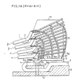
- FIG.1A shows structure nearby a contact and arc extinguish grids 10 of a circuit breaker of the prior art.
- a fixed contact 4 and an arc runner 5 are fixed on a fixed arm 3.
- the fixed arm 3 is fixed by a bolt 12 and a folded tip part 31 of the fixed arm 3 is also fixed by a bolt 12.
- a movable contact 2 is provided on a movable arm 1. In a closing state, the movable contact 2 and fixed contact 4 are contacted.
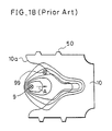
- FIG.1B is a plan view for showing a relation between the arc 9 and the arc extinguish grind 10.
- the arc extinguish grid 10 is made of magnetic material and has notch 10a for introducing the arc. Because the notch 10a is formed, lines of magnetic force are deflected as shown in FIG.1B. Therefore, the arc 9 is moved in a direction shown by an arrow A. Referring not to FIG.1A, the arc is moved from 9b to 9f through 9c, 9d and 9e. Moved arc 9 is stretched, divided and extinguished as described above.
- the conventional circuit breaker as above suffers the following problems.
- a circuit breaker in accordance with the present invention comprises: a fixed arm, a fixed contact provided on the fixed arm, a movable arm which is provided movable by a releasing means, a movable contact which provided on the movable arm in a manner to be disconnected from the fixed contact by the releasing means, an arc-runner end of which is fixed to the fixed arm, and arc extinguished grids of magnetic material which are positioned in an upper space of the arc-runner and have their surfaces nearby perpendicular to an arc, and have insulation films thereon formed on the surface of arc-introducing parts thereof.
- a circuit breaker in accordance with the present invention comprises: a fixed arm, a fixed contact provided on the fixed arm, a movable arm which is provided movable by a releasing means, a movable contact which is disconnected from the fixed contact by the releasing means, an arc-runner end of which is fixed to the fixed arm, and arc extinguish grids of magnetic material which are positioned upper space of the arc-runner and which surfaces are nearly perpendicular to an arc wherein insulation films are formed at rear end thereof.
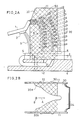
- FIG.2A shows a preferred embodiment of a circuit breaker embodying the present invention.
- a fixed contact 4 and an arc runner 5 are fixed on a fixed arm 3.
- the fixed arm 3 is fixed by a bolt 12, and a folded tip part 31 of the fixed arm 3 is also fixed by a bolt 12.
- a movable contact 2 is provided on a movable arm 1.
- Arc extinguish grids 30 are fixed to side plates 11 by caulking protrusions 50 provided at side part of the extinguish grids 30 after inserting the protrusions 50 into holes of the side plates 11.
- the arc extinguish grid 30 is made of magnetic material and has its surface nearly perpendicular to an arc.
- An insulation film 32 covers a front part of the extinguish grid 30.
- the extinguish grid 30 has insulation part 32 and metallic part 34.
- Arc-proof insulating paint such as arc-proof epoxy coating paint (Limitrack: trademark of Ryoden Kasei), or liquid ceramic, is suitable for the insulation film 32.
- the insulation film 32 is formed by dipping the arc extinguish grids 30 and the side plates 11 into a solution of the arc-proof insulating paint.
- the insulation film 32 covers arc introducing part 30b of arc extinguish grid 30.
- the caulked parts 50 are also covered with the arc-proof insulating paint, the caulked parts 50 are prevented from rusting.
- the arc extinguish grid 10 is made of magnetic material such as iron and has notch 10a for introducing the arc. Because the notch 10a is formed, lines of magnetic force are deflected (see FIG.1B). Therefore, the arc 9 is moved in the direction shown by an arrow A.
- thermoelectrons are not emitted from the arc extinguish grid 30 since the arc-proof insulation film 32 is formed. Therefore, the arc does not stay, but is smoothly move in the metallic part 34 of arc extinguish grid 30.
- the arc 9 touches the metallic part 34 of the arc extinguish grid 30, the arc 9 is smoothly quenched.
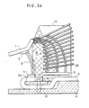
- FIG.3A is a sectional view of a circuit breaker of another embodiment
- FIG.3B is a plan view thereof.
- the insulation films 32 are formed in such a manner that the arc extinguish grid is covered by the insulation film 32 wider at the part near the arc-runner 5, but narrower at the portion far from the arc-runner 5.
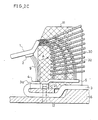
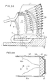
- FIG.4A is a sectional view of a circuit breaker of still another embodiment which is suitable for high voltage and large current
- FIG.4B is a plan view thereof.
- the insulation films 32 are formed at rear ends of the arc extinguish grids 30.
- the arc extinguish grid 10 is made of magnetic material and has notch 10a for introducing the arc. Because the notch 10a is formed, lines of magnetic force are deflected (see FIG.1B). Therefore, the arc 9 is moved in the direction shown by an arrow A. Finally, the arc 9 is moved in the rear ends of the arc extinguish grids 30. Because the rear ends of of the grids 30 are covered by the insulation film 32, shortcircuiting by an arc at the rear part as 9g in FIG.1A is prevented, and thus superior and stable breaker efficiency is obtainable.
- FIG.5A and FIG.5B show still other modified embodiment, wherein the insulation film 32 covers limited part behind the notch 30a of the arc extinguish grid 30.
- the insulation film 32 covers limited part behind the notch 30a of the arc extinguish grid 30.
- arc contact time to the metallic part 34 of the arc extinguish grid 30 is longer than that in the embodiment of FIG.4A. Therefore, the cooling and quenching of arc is efficient.
Landscapes
- Arc-Extinguishing Devices That Are Switches (AREA)
- Breakers (AREA)
Applications Claiming Priority (8)
| Application Number | Priority Date | Filing Date | Title |
|---|---|---|---|
| JP9902687A JPS63264840A (ja) | 1987-04-21 | 1987-04-21 | 回路しや断器 |
| JP9902987A JPS63264843A (ja) | 1987-04-21 | 1987-04-21 | 回路しや断器 |
| JP9902887A JPS63264842A (ja) | 1987-04-21 | 1987-04-21 | 回路しや断器 |
| JP9902787A JPS63264841A (ja) | 1987-04-21 | 1987-04-21 | 回路しや断器 |
| JP99028/87 | 1987-04-21 | ||
| JP99027/87 | 1987-04-21 | ||
| JP99026/87 | 1987-04-21 | ||
| JP99029/87 | 1987-04-21 |
Publications (3)
| Publication Number | Publication Date |
|---|---|
| EP0288040A2 true EP0288040A2 (de) | 1988-10-26 |
| EP0288040A3 EP0288040A3 (en) | 1990-06-13 |
| EP0288040B1 EP0288040B1 (de) | 1994-03-02 |
Family
ID=27468696
Family Applications (1)
| Application Number | Title | Priority Date | Filing Date |
|---|---|---|---|
| EP88106330A Expired - Lifetime EP0288040B1 (de) | 1987-04-21 | 1988-04-20 | Schutzschalter |
Country Status (3)
| Country | Link |
|---|---|
| EP (1) | EP0288040B1 (de) |
| KR (1) | KR910001537B1 (de) |
| DE (1) | DE3888007T2 (de) |
Cited By (7)
| Publication number | Priority date | Publication date | Assignee | Title |
|---|---|---|---|---|
| CH681933A5 (en) * | 1991-03-14 | 1993-06-15 | Secheron Sa | Electrical switch with arc-quenching system - has plate of magnetic material with coupled plate of insulation having cut-away section near to arcing point |
| DE19803925A1 (de) * | 1998-02-02 | 1999-08-05 | Maier & Cie C | Installationsschalter |
| CN1298002C (zh) * | 2004-02-06 | 2007-01-31 | 西安交通大学 | 一种带产气绝缘夹层的栅片灭弧室 |
| CN104969320A (zh) * | 2012-12-04 | 2015-10-07 | 印度拿丁集团公司 | 电气开关装置中用于灭弧的灭弧室配置 |
| EP3748666A4 (de) * | 2018-02-01 | 2021-06-30 | Mitsubishi Electric Corporation | Schutzschalter und schutzschaltverfahren |
| EP3933866A1 (de) * | 2020-07-01 | 2022-01-05 | ABB Schweiz AG | Schaltvorrichtung für stromverteilungsnetze |
| CN114284895A (zh) * | 2022-01-11 | 2022-04-05 | 华科电工工程股份有限公司 | 具备智能语音交互控制系统的高压开关柜 |
Families Citing this family (1)
| Publication number | Priority date | Publication date | Assignee | Title |
|---|---|---|---|---|
| DE10242310A1 (de) * | 2001-11-16 | 2003-07-10 | Abb Patent Gmbh | Lichtbogenlöschanordnung für ein elektrisches Schaltgerät |
Family Cites Families (5)
| Publication number | Priority date | Publication date | Assignee | Title |
|---|---|---|---|---|
| NL295859A (de) * | 1962-07-27 | |||
| DE2419656B2 (de) * | 1974-04-24 | 1978-03-23 | Licentia Patent-Verwaltungs-Gmbh, 6000 Frankfurt | Löschblechstapel, insbesondere für Leitungsschutzschalter, der auf einen Isolierstoffträger aufgeheftet ist |
| DE2616825C3 (de) * | 1976-04-15 | 1981-07-02 | Brown, Boveri & Cie Ag, 6800 Mannheim | Leitungsschutzschalter |
| IT1129691B (it) * | 1980-01-31 | 1986-06-11 | Elettromeccanica Spa Cge Comp | Complesso di estinzione rapida dell'arco elettrico in dispositivi di interruzione come interruttori elettrici |
| DE3531040C1 (de) * | 1985-08-30 | 1987-06-04 | Licentia Gmbh | Loescheinrichtung fuer einen Allstrom-Leitungsschutzschalter |
-
1988
- 1988-03-26 KR KR1019880003295A patent/KR910001537B1/ko not_active Expired
- 1988-04-20 DE DE3888007T patent/DE3888007T2/de not_active Expired - Fee Related
- 1988-04-20 EP EP88106330A patent/EP0288040B1/de not_active Expired - Lifetime
Cited By (9)
| Publication number | Priority date | Publication date | Assignee | Title |
|---|---|---|---|---|
| CH681933A5 (en) * | 1991-03-14 | 1993-06-15 | Secheron Sa | Electrical switch with arc-quenching system - has plate of magnetic material with coupled plate of insulation having cut-away section near to arcing point |
| DE19803925A1 (de) * | 1998-02-02 | 1999-08-05 | Maier & Cie C | Installationsschalter |
| CN1298002C (zh) * | 2004-02-06 | 2007-01-31 | 西安交通大学 | 一种带产气绝缘夹层的栅片灭弧室 |
| CN104969320A (zh) * | 2012-12-04 | 2015-10-07 | 印度拿丁集团公司 | 电气开关装置中用于灭弧的灭弧室配置 |
| CN104969320B (zh) * | 2012-12-04 | 2018-04-03 | 印度拿丁集团公司 | 电气开关装置中用于灭弧的灭弧室配置 |
| EP3748666A4 (de) * | 2018-02-01 | 2021-06-30 | Mitsubishi Electric Corporation | Schutzschalter und schutzschaltverfahren |
| EP3933866A1 (de) * | 2020-07-01 | 2022-01-05 | ABB Schweiz AG | Schaltvorrichtung für stromverteilungsnetze |
| CN114284895A (zh) * | 2022-01-11 | 2022-04-05 | 华科电工工程股份有限公司 | 具备智能语音交互控制系统的高压开关柜 |
| CN114284895B (zh) * | 2022-01-11 | 2024-06-07 | 华科电工工程股份有限公司 | 具备智能语音交互控制系统的高压开关柜 |
Also Published As
| Publication number | Publication date |
|---|---|
| KR910001537B1 (ko) | 1991-03-15 |
| KR880013202A (ko) | 1988-11-30 |
| EP0288040A3 (en) | 1990-06-13 |
| DE3888007T2 (de) | 1994-06-09 |
| EP0288040B1 (de) | 1994-03-02 |
| DE3888007D1 (de) | 1994-04-07 |
Similar Documents
| Publication | Publication Date | Title |
|---|---|---|
| KR100304150B1 (ko) | 회로차단기의아아크소멸장치 | |
| US4885441A (en) | Circuit Breaker | |
| US4642428A (en) | Circuit interrupter | |
| EP0288040A2 (de) | Schutzschalter | |
| US4616203A (en) | Electromagnetic contactor | |
| US5847937A (en) | Method for contacting high-current connecting elements of an electrical component, and assembly made by such a method | |
| US3564184A (en) | Electric circuit breaker | |
| US3586809A (en) | Reed switch for rapid cycle,high power applications | |
| US5463199A (en) | DC-rated circuit breaker with arc suppressor | |
| US4453053A (en) | Circuit breaker with arc restricting device | |
| US4409445A (en) | Circuit breaker | |
| CA1222787A (en) | Arrangement for enhancing the arc blow and/or extinction between the contacts of circuit breakers and the like | |
| US4409444A (en) | Circuit breaker | |
| JP2993346B2 (ja) | 消弧装置 | |
| EP0061097A2 (de) | Schalter | |
| KR880001824Y1 (ko) | 회로차단기 | |
| JPS63264841A (ja) | 回路しや断器 | |
| JPS6376216A (ja) | 回路しや断器 | |
| JPS6376217A (ja) | 回路しや断器 | |
| JPH0113315Y2 (de) | ||
| JPH0113314Y2 (de) | ||
| JPH0218512Y2 (de) | ||
| JPS63264840A (ja) | 回路しや断器 | |
| KR880001823Y1 (ko) | 회로 차단기 | |
| KR880001826Y1 (ko) | 회로 차단기 |
Legal Events
| Date | Code | Title | Description |
|---|---|---|---|
| PUAI | Public reference made under article 153(3) epc to a published international application that has entered the european phase |
Free format text: ORIGINAL CODE: 0009012 |
|
| 17P | Request for examination filed |
Effective date: 19880420 |
|
| AK | Designated contracting states |
Kind code of ref document: A2 Designated state(s): CH DE FR GB IT LI |
|
| PUAL | Search report despatched |
Free format text: ORIGINAL CODE: 0009013 |
|
| AK | Designated contracting states |
Kind code of ref document: A3 Designated state(s): CH DE FR GB IT LI |
|
| 17Q | First examination report despatched |
Effective date: 19920915 |
|
| GRAA | (expected) grant |
Free format text: ORIGINAL CODE: 0009210 |
|
| AK | Designated contracting states |
Kind code of ref document: B1 Designated state(s): CH DE FR GB IT LI |
|
| REF | Corresponds to: |
Ref document number: 3888007 Country of ref document: DE Date of ref document: 19940407 |
|
| PGFP | Annual fee paid to national office [announced via postgrant information from national office to epo] |
Ref country code: CH Payment date: 19940411 Year of fee payment: 7 |
|
| ITF | It: translation for a ep patent filed | ||
| ET | Fr: translation filed | ||
| PLBE | No opposition filed within time limit |
Free format text: ORIGINAL CODE: 0009261 |
|
| STAA | Information on the status of an ep patent application or granted ep patent |
Free format text: STATUS: NO OPPOSITION FILED WITHIN TIME LIMIT |
|
| 26N | No opposition filed | ||
| PGFP | Annual fee paid to national office [announced via postgrant information from national office to epo] |
Ref country code: GB Payment date: 19950410 Year of fee payment: 8 |
|
| PGFP | Annual fee paid to national office [announced via postgrant information from national office to epo] |
Ref country code: FR Payment date: 19950411 Year of fee payment: 8 |
|
| PGFP | Annual fee paid to national office [announced via postgrant information from national office to epo] |
Ref country code: DE Payment date: 19950421 Year of fee payment: 8 |
|
| PG25 | Lapsed in a contracting state [announced via postgrant information from national office to epo] |
Ref country code: LI Effective date: 19950430 Ref country code: CH Effective date: 19950430 |
|
| REG | Reference to a national code |
Ref country code: GB Ref legal event code: 746 Effective date: 19951026 |
|
| REG | Reference to a national code |
Ref country code: CH Ref legal event code: PL |
|
| REG | Reference to a national code |
Ref country code: FR Ref legal event code: D6 |
|
| PG25 | Lapsed in a contracting state [announced via postgrant information from national office to epo] |
Ref country code: GB Effective date: 19960420 |
|
| GBPC | Gb: european patent ceased through non-payment of renewal fee |
Effective date: 19960420 |
|
| PG25 | Lapsed in a contracting state [announced via postgrant information from national office to epo] |
Ref country code: FR Effective date: 19961227 |
|
| PG25 | Lapsed in a contracting state [announced via postgrant information from national office to epo] |
Ref country code: DE Effective date: 19970101 |
|
| REG | Reference to a national code |
Ref country code: FR Ref legal event code: ST |
|
| PG25 | Lapsed in a contracting state [announced via postgrant information from national office to epo] |
Ref country code: IT Free format text: LAPSE BECAUSE OF NON-PAYMENT OF DUE FEES;WARNING: LAPSES OF ITALIAN PATENTS WITH EFFECTIVE DATE BEFORE 2007 MAY HAVE OCCURRED AT ANY TIME BEFORE 2007. THE CORRECT EFFECTIVE DATE MAY BE DIFFERENT FROM THE ONE RECORDED. Effective date: 20050420 |