EP0288097A1 - Construction de fixation pour fixation détachable d'un accessoire à un guidon de vélo - Google Patents
Construction de fixation pour fixation détachable d'un accessoire à un guidon de vélo Download PDFInfo
- Publication number
- EP0288097A1 EP0288097A1 EP88200560A EP88200560A EP0288097A1 EP 0288097 A1 EP0288097 A1 EP 0288097A1 EP 88200560 A EP88200560 A EP 88200560A EP 88200560 A EP88200560 A EP 88200560A EP 0288097 A1 EP0288097 A1 EP 0288097A1
- Authority
- EP
- European Patent Office
- Prior art keywords
- support arm
- fastening structure
- structure according
- bicycle handlebar
- bicycle
- Prior art date
- Legal status (The legal status is an assumption and is not a legal conclusion. Google has not performed a legal analysis and makes no representation as to the accuracy of the status listed.)
- Granted
Links
Images

Classifications
-
- B—PERFORMING OPERATIONS; TRANSPORTING
- B62—LAND VEHICLES FOR TRAVELLING OTHERWISE THAN ON RAILS
- B62J—CYCLE SADDLES OR SEATS; AUXILIARY DEVICES OR ACCESSORIES SPECIALLY ADAPTED TO CYCLES AND NOT OTHERWISE PROVIDED FOR, e.g. ARTICLE CARRIERS OR CYCLE PROTECTORS
- B62J11/00—Supporting arrangements specially adapted for fastening specific devices to cycles, e.g. supports for attaching maps
-
- B—PERFORMING OPERATIONS; TRANSPORTING
- B62—LAND VEHICLES FOR TRAVELLING OTHERWISE THAN ON RAILS
- B62J—CYCLE SADDLES OR SEATS; AUXILIARY DEVICES OR ACCESSORIES SPECIALLY ADAPTED TO CYCLES AND NOT OTHERWISE PROVIDED FOR, e.g. ARTICLE CARRIERS OR CYCLE PROTECTORS
- B62J3/00—Acoustic signal devices; Arrangement of such devices on cycles
- B62J3/02—Mechanical devices
- B62J3/04—Mechanical devices activated by the rider, e.g. bells or horns
-
- B—PERFORMING OPERATIONS; TRANSPORTING
- B62—LAND VEHICLES FOR TRAVELLING OTHERWISE THAN ON RAILS
- B62K—CYCLES; CYCLE FRAMES; CYCLE STEERING DEVICES; RIDER-OPERATED TERMINAL CONTROLS SPECIALLY ADAPTED FOR CYCLES; CYCLE AXLE SUSPENSIONS; CYCLE SIDECARS, FORECARS, OR THE LIKE
- B62K21/00—Steering devices
- B62K21/12—Handlebars; Handlebar stems
Definitions
- the invention relates to a mounting structure for detachable attachment of an accessory to a bicycle handlebar.
- the purpose of the invention is a way of attaching handlebar fittings to a bicycle handlebar which does not have the disadvantages mentioned above and which makes it possible to reduce the number of assembly operations.
- a bicycle handlebar is understood to mean any handlebar that is designed in a similar manner to a motorbike handlebar, a moped handlebar, a scooter handlebar, etc.
- a fastening structure of the type mentioned at the outset is characterized by a support arm, provided with first means, by means of which the support arm can be freely supported on a bicycle handlebar with a first end part thereof, and second means, by means of which an accessory is close to the support arm the other end part of the same is attachable.
- the support arm is designed to be able to be attached to the underside of a bicycle handlebar with the first aids, the support arm being attached to the bottom of the bicycle Handlebar to be connected end part is widened into a shell and is curved with a radius of curvature that corresponds to the radius of the outer wall of the bicycle handlebar.
- the shell by means of which the support arm can be fastened against the underside of the bicycle handlebar, is provided with an opening which can be brought into alignment with an opening which is to be fitted in the underside of the bicycle handlebar, so that the support arm can be firmly attached to the bicycle handlebar by means of a single bolt is connectable.
- the support arm is made of a plastic material, e.g. made of a polyacetal resin.
- the fastening structure using the support arm according to the invention makes it possible to position the parts to be fastened, such as a bicycle bell or an adjustment device for the bicycle gear shift, in such a way that the part in question lies within the curvature formed by the bicycle handlebar, which defines the transition from the Handle of the bicycle handlebar to the handlebar center forms, and with the top of the part below the top of the handlebar.
- This provides maximum protection, while an additional advantage is the possibility that the bicycle can be placed on the ground for repair purposes without damaging the bicycle bell, the adjustment device or any other accessory attached according to the invention.
- the shell-shaped part of the support arm, with which it is mounted against the underside of the bicycle handlebar, is shaped on the outside (convex side) in such a way that the majority (about 80%) of the commercially available levers for rope brakes without using the usual associated clamping band with only a single bolt, ie the bolt belonging to the support arm can be fastened together with the support arm to the bicycle handlebar.
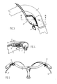
- a bicycle bell 3 is fastened to the reproduced bicycle handlebar 1 in the left curvature thereof via a support arm 2 (FIG. 1 and FIG 2).
- the support arm can advantageously be made of polyacetal resin, but other materials can also be used.
- a curved shell 4 can be seen at one end, which has an opening 5.
- the curvature of the shell 4 is such that the shell fits snugly against the outer wall of the bicycle handlebar 1.
- the desired position of the shell 4 is found by opening the opening 5 with one in the bicycle handlebar, e.g. brings the screw-provided opening into alignment, whereupon the shell 4 can be fastened against the handlebar 1 by means of a single bolt 6 and with it the entire support arm 2 and the bicycle bell 3 attached to it.
- the bicycle bell 3 comprises a singing bowl 7 which is suspended from a connector 8 of the support arm 2 located at the other end.
- the support arm is formed in such a way that it also serves as a space and delimitation for the bobbin-making mechanism.
- the clapper mechanism is formed from a bent leaf spring 9 made of polyacetal resin and a clapper 10 formed at the end of the leaf spring from polyacetal resin.
- the clapper and the leaf spring are preferably made in one piece with the support arm by injection molding.
- the bell is activated by using a finger, e.g. the thumb, the clapper 10 moves sideways in the direction of the bicycle handlebar 1 and then releases it. Under the influence of the spring tension, the clapper 10 then moves back and strikes the singing bowl 7, producing a single bright sound.
- Line H gives the upper horizontal level which is normally determined by the handles of a bicycle handlebar when the bicycle is in the use position.
- Figure 2 clearly shows that the top of the support arm or the bell construction does not go beyond level H.
- the clapper mechanism can also consist of a metal leaf spring or a helical spring provided with a clapper.
- the spring can be suitably e.g. by clamping, screwing, riveting, etc. be attached to the support arm.
- FIG. 3 and FIG. 4 the fastening of an adjusting device of a bicycle gear shift by means of a similar support arm 31 made of polyacetal resin to the bicycle handlebar 1 is shown in the right curvature thereof.
- the adjusting device can be recognized by the lever 11 belonging to it, the position of which can be adjusted into the various positions by a thumb movement if desired.
- the mounting arm 31 is fastened to the underside of the bicycle handlebar 1 in a manner analogous to that of the bell construction in FIGS. 1 and 2 via a shell 4, an opening 5 and a bolt 6.
- the other end of the support arm 31 is formed into an inverted box or such a shell 12, in which the mechanism 15 to be actuated by the lever 11 is attached.
- the box 12 is closed with a bottom cover 13 which is fastened in a connecting piece 16 by means of a screw 14.
- the nozzle 16 extends like the nozzle 8 downwards from the relevant end of the support arm.
- FIG. 4 it can be seen (FIG. 4) that the support arm lies completely below the horizontal plane H, while the housing for the adjusting device also does not come out below the bicycle handlebar on the underside thereof and is therefore optimal in the vertical sense is protected. Incidentally, this is also the case with the bell construction shown in FIGS. 1 and 2.
- a support arm according to the invention can be used together with at least the part of an actuating member for a brake cable, clutch cable or the like which is to be fixed firmly to the handlebar. be formed in one piece.
Landscapes
- Engineering & Computer Science (AREA)
- Mechanical Engineering (AREA)
- Physics & Mathematics (AREA)
- Acoustics & Sound (AREA)
- Steering Devices For Bicycles And Motorcycles (AREA)
Applications Claiming Priority (2)
| Application Number | Priority Date | Filing Date | Title |
|---|---|---|---|
| NL8700712 | 1987-03-26 | ||
| NL8700712A NL8700712A (nl) | 1987-03-26 | 1987-03-26 | Orgaan voor losneembare bevestiging aan een rijwielstuur van een accessoire. |
Publications (2)
| Publication Number | Publication Date |
|---|---|
| EP0288097A1 true EP0288097A1 (fr) | 1988-10-26 |
| EP0288097B1 EP0288097B1 (fr) | 1992-03-11 |
Family
ID=19849768
Family Applications (1)
| Application Number | Title | Priority Date | Filing Date |
|---|---|---|---|
| EP88200560A Expired - Lifetime EP0288097B1 (fr) | 1987-03-26 | 1988-03-25 | Construction de fixation pour fixation détachable d'un accessoire à un guidon de vélo |
Country Status (3)
| Country | Link |
|---|---|
| EP (1) | EP0288097B1 (fr) |
| DE (2) | DE8803735U1 (fr) |
| NL (1) | NL8700712A (fr) |
Cited By (3)
| Publication number | Priority date | Publication date | Assignee | Title |
|---|---|---|---|---|
| DE4029012A1 (de) * | 1990-09-13 | 1992-05-27 | Rixen & Kaul Gmbh | Fahrrad, abnehmbares bauteil eines fahrrades und zubehoer fuer ein zweirad |
| DE4409251C1 (de) * | 1994-03-18 | 1995-06-22 | Fichtel & Sachs Ag | Schaltbetätigungseinrichtung für Wechselgetriebe an Fahrrädern |
| DE102020119144B3 (de) | 2020-07-21 | 2022-01-20 | Audi Aktiengesellschaft | Anordnung zum Erzeugen eines akustischen Signals |
Families Citing this family (1)
| Publication number | Priority date | Publication date | Assignee | Title |
|---|---|---|---|---|
| NL1034100C2 (nl) * | 2007-07-05 | 2009-01-06 | Batavus Bv | Fietsstuur, samenstel van een dergelijk fietsstuur en een fietsbel, fiets voorzien van een dergelijk fietsstuur, alsmede werkwijze voor het vervaardigen van een dergelijk fietsstuur. |
Citations (4)
| Publication number | Priority date | Publication date | Assignee | Title |
|---|---|---|---|---|
| FR1009276A (fr) * | 1948-06-02 | 1952-05-27 | Perfectionnements aux timbres avertisseurs pour cycles ou autres | |
| FR1109220A (fr) * | 1954-07-19 | 1956-01-24 | Anciens Etablissements Paul Ma | Dispositif d'attache perfectionné d'un timbre sur une bicyclette ou véhicule analogue |
| GB850877A (en) * | 1958-05-19 | 1960-10-12 | Lucas Industries Ltd | Bicycle or like bells |
| NL8301969A (nl) * | 1983-06-02 | 1985-01-02 | Widek B V | Fietsbel. |
-
1987
- 1987-03-26 NL NL8700712A patent/NL8700712A/nl not_active Application Discontinuation
-
1988
- 1988-03-19 DE DE8803735U patent/DE8803735U1/de not_active Expired
- 1988-03-25 DE DE8888200560T patent/DE3868966D1/de not_active Expired - Lifetime
- 1988-03-25 EP EP88200560A patent/EP0288097B1/fr not_active Expired - Lifetime
Patent Citations (4)
| Publication number | Priority date | Publication date | Assignee | Title |
|---|---|---|---|---|
| FR1009276A (fr) * | 1948-06-02 | 1952-05-27 | Perfectionnements aux timbres avertisseurs pour cycles ou autres | |
| FR1109220A (fr) * | 1954-07-19 | 1956-01-24 | Anciens Etablissements Paul Ma | Dispositif d'attache perfectionné d'un timbre sur une bicyclette ou véhicule analogue |
| GB850877A (en) * | 1958-05-19 | 1960-10-12 | Lucas Industries Ltd | Bicycle or like bells |
| NL8301969A (nl) * | 1983-06-02 | 1985-01-02 | Widek B V | Fietsbel. |
Cited By (3)
| Publication number | Priority date | Publication date | Assignee | Title |
|---|---|---|---|---|
| DE4029012A1 (de) * | 1990-09-13 | 1992-05-27 | Rixen & Kaul Gmbh | Fahrrad, abnehmbares bauteil eines fahrrades und zubehoer fuer ein zweirad |
| DE4409251C1 (de) * | 1994-03-18 | 1995-06-22 | Fichtel & Sachs Ag | Schaltbetätigungseinrichtung für Wechselgetriebe an Fahrrädern |
| DE102020119144B3 (de) | 2020-07-21 | 2022-01-20 | Audi Aktiengesellschaft | Anordnung zum Erzeugen eines akustischen Signals |
Also Published As
| Publication number | Publication date |
|---|---|
| EP0288097B1 (fr) | 1992-03-11 |
| NL8700712A (nl) | 1988-10-17 |
| DE8803735U1 (de) | 1988-06-01 |
| DE3868966D1 (de) | 1992-04-16 |
Similar Documents
| Publication | Publication Date | Title |
|---|---|---|
| DE4312032C2 (de) | Kupplung zum Befestigen und Lösen von Ausrüstungsgegenständen | |
| EP0288097A1 (fr) | Construction de fixation pour fixation détachable d'un accessoire à un guidon de vélo | |
| DE3226357C2 (de) | Vorrichtung zur Messung der mit einem Fahrrad zurückgelegten Wegstrecke | |
| EP0049904A2 (fr) | Fixation pour cadenas à anses longues | |
| DE3537615C2 (fr) | ||
| EP0041058B1 (fr) | Dispositif de fixation pour guidon de motos | |
| DE3308977A1 (de) | Buegelschloss | |
| DE102021110692B3 (de) | Elektrofahrrad und Batteriehalterung | |
| DE3023693C2 (de) | Lenkradanordnung, insbesondere für Ackerschlepper | |
| DE102019120715B4 (de) | Lenkrad | |
| DE69626379T2 (de) | Vorrichtung zum Tragen von Kabeln für Kettenschalter | |
| DE4341586A1 (de) | Schutzblech für ein Fahrrad | |
| DE10042821C2 (de) | Anschließvorrichtung für Fahrräder | |
| DE3412935C2 (de) | Vorrichtung zur Sicherung eines mittels Gurtes bedienbaren Rolladens | |
| DE3002941C2 (de) | Diebstahlsicherung für ein auf einem Kraftfahrzeug-Lastträger befindliches Surfbrett | |
| DE102021119421B3 (de) | Fahrradtransportbox und Fahrrad mit einer Fahrradtransportbox, Fahrrad, Zubehörteil und Verbinder | |
| DE3509893C2 (fr) | ||
| DE2727951A1 (de) | Handhebelarmatur fuer den lenker eines zweiradfahrzeuges | |
| DE202018101690U1 (de) | Fußrastenvorrichtung | |
| DE19635762C2 (de) | Einstellbarer Lenkervorbau für ein Fahrrad | |
| EP0079616A1 (fr) | Bicyclette | |
| DE9407682U1 (de) | Vorrichtung für die Steuerung der Bremsung von mit einem automatischen Getriebe versehenen Kraftfahrzeugen, die sich in Parkstellung befinden | |
| DE19854321A1 (de) | Auto Kennzeichen Befestigungen mit Rahmen | |
| DE3303525A1 (de) | Vorrichtung zur wahlweisen motorisierung von fahrraedern | |
| DE3822379A1 (de) | Gasdrehgriff eines motorrades |
Legal Events
| Date | Code | Title | Description |
|---|---|---|---|
| PUAI | Public reference made under article 153(3) epc to a published international application that has entered the european phase |
Free format text: ORIGINAL CODE: 0009012 |
|
| AK | Designated contracting states |
Kind code of ref document: A1 Designated state(s): DE FR GB NL |
|
| 17P | Request for examination filed |
Effective date: 19890412 |
|
| 17Q | First examination report despatched |
Effective date: 19900621 |
|
| GRAA | (expected) grant |
Free format text: ORIGINAL CODE: 0009210 |
|
| AK | Designated contracting states |
Kind code of ref document: B1 Designated state(s): DE FR GB NL |
|
| REF | Corresponds to: |
Ref document number: 3868966 Country of ref document: DE Date of ref document: 19920416 |
|
| ET | Fr: translation filed | ||
| GBT | Gb: translation of ep patent filed (gb section 77(6)(a)/1977) | ||
| PLBE | No opposition filed within time limit |
Free format text: ORIGINAL CODE: 0009261 |
|
| STAA | Information on the status of an ep patent application or granted ep patent |
Free format text: STATUS: NO OPPOSITION FILED WITHIN TIME LIMIT |
|
| 26N | No opposition filed | ||
| PGFP | Annual fee paid to national office [announced via postgrant information from national office to epo] |
Ref country code: GB Payment date: 19990722 Year of fee payment: 12 |
|
| PGFP | Annual fee paid to national office [announced via postgrant information from national office to epo] |
Ref country code: DE Payment date: 19990723 Year of fee payment: 12 |
|
| PGFP | Annual fee paid to national office [announced via postgrant information from national office to epo] |
Ref country code: FR Payment date: 19990730 Year of fee payment: 12 |
|
| PG25 | Lapsed in a contracting state [announced via postgrant information from national office to epo] |
Ref country code: GB Free format text: LAPSE BECAUSE OF NON-PAYMENT OF DUE FEES Effective date: 20000325 |
|
| GBPC | Gb: european patent ceased through non-payment of renewal fee |
Effective date: 20000325 |
|
| PG25 | Lapsed in a contracting state [announced via postgrant information from national office to epo] |
Ref country code: FR Free format text: LAPSE BECAUSE OF NON-PAYMENT OF DUE FEES Effective date: 20001130 |
|
| REG | Reference to a national code |
Ref country code: FR Ref legal event code: ST |
|
| PG25 | Lapsed in a contracting state [announced via postgrant information from national office to epo] |
Ref country code: DE Free format text: LAPSE BECAUSE OF NON-PAYMENT OF DUE FEES Effective date: 20010103 |
|
| PGFP | Annual fee paid to national office [announced via postgrant information from national office to epo] |
Ref country code: NL Payment date: 20060315 Year of fee payment: 19 |
|
| NLV4 | Nl: lapsed or anulled due to non-payment of the annual fee |
Effective date: 20071001 |
|
| PG25 | Lapsed in a contracting state [announced via postgrant information from national office to epo] |
Ref country code: NL Free format text: LAPSE BECAUSE OF NON-PAYMENT OF DUE FEES Effective date: 20071001 |