EP0288260B1 - Stimulateur électrique ergonométrique par voie transcutanée de nerfs - Google Patents
Stimulateur électrique ergonométrique par voie transcutanée de nerfs Download PDFInfo
- Publication number
- EP0288260B1 EP0288260B1 EP88303547A EP88303547A EP0288260B1 EP 0288260 B1 EP0288260 B1 EP 0288260B1 EP 88303547 A EP88303547 A EP 88303547A EP 88303547 A EP88303547 A EP 88303547A EP 0288260 B1 EP0288260 B1 EP 0288260B1
- Authority
- EP
- European Patent Office
- Prior art keywords
- switch
- housing
- electrical
- amplitude
- nerve stimulator
- Prior art date
- Legal status (The legal status is an assumption and is not a legal conclusion. Google has not performed a legal analysis and makes no representation as to the accuracy of the status listed.)
- Expired - Lifetime
Links
- 210000005036 nerve Anatomy 0.000 title claims description 35
- 230000000638 stimulation Effects 0.000 claims description 19
- 230000007423 decrease Effects 0.000 claims description 7
- 230000007246 mechanism Effects 0.000 description 6
- 208000002193 Pain Diseases 0.000 description 5
- 238000010586 diagram Methods 0.000 description 4
- 208000005171 Dysmenorrhea Diseases 0.000 description 3
- 208000000094 Chronic Pain Diseases 0.000 description 2
- 208000008930 Low Back Pain Diseases 0.000 description 2
- 230000000994 depressogenic effect Effects 0.000 description 2
- 239000000463 material Substances 0.000 description 2
- 230000007935 neutral effect Effects 0.000 description 2
- 206010013935 Dysmenorrhoea Diseases 0.000 description 1
- 206010033372 Pain and discomfort Diseases 0.000 description 1
- 210000001015 abdomen Anatomy 0.000 description 1
- 210000004556 brain Anatomy 0.000 description 1
- 210000000481 breast Anatomy 0.000 description 1
- 238000010276 construction Methods 0.000 description 1
- 238000012937 correction Methods 0.000 description 1
- 230000003247 decreasing effect Effects 0.000 description 1
- 239000013013 elastic material Substances 0.000 description 1
- 230000000737 periodic effect Effects 0.000 description 1
- 230000000284 resting effect Effects 0.000 description 1
- 238000006748 scratching Methods 0.000 description 1
- 230000002393 scratching effect Effects 0.000 description 1
- 238000007493 shaping process Methods 0.000 description 1
- 230000000007 visual effect Effects 0.000 description 1
Images


Classifications
-
- A—HUMAN NECESSITIES
- A61—MEDICAL OR VETERINARY SCIENCE; HYGIENE
- A61N—ELECTROTHERAPY; MAGNETOTHERAPY; RADIATION THERAPY; ULTRASOUND THERAPY
- A61N1/00—Electrotherapy; Circuits therefor
- A61N1/18—Applying electric currents by contact electrodes
- A61N1/32—Applying electric currents by contact electrodes alternating or intermittent currents
- A61N1/36—Applying electric currents by contact electrodes alternating or intermittent currents for stimulation
- A61N1/36014—External stimulators, e.g. with patch electrodes
- A61N1/36021—External stimulators, e.g. with patch electrodes for treatment of pain
Definitions
- the present invention relates generally to transcutaneous electrical nerve stimulators and more particularly to transcutaneous electrical nerve stimulators designed to alleviate chronic pain.
- Transcutaneous electrical nerve stimulators are typically utilized to mask pain signals of a human body before they reach the brain giving the subject apparent relief from the pain. Electrical pulses are delivered to the skin of the subject by one or more electrodes. The subject typically can control the transcutaneous electrical nerve stimulator through adjustment of its output current of the pulses.
- the transcutaneous electrical nerve stimulator may have a plurality of outputs, e.g., two, channels, each simultaneously and independently providing electrical stimulation pulses.
- transcutaneous electrical nerve stimulator is for chronic pain situations such as those related to menstrual pain, dysmenorrhea and for lower back pain.
- US-A-4 324 235 discloses a transcutaneous pain control apparatus in a rectangular case with well rounded edges and knurled rotatable disc-switches for control of the emitted pulses.
- a transcutaneous electrical nerve stimulator is desirably worn on the body of the person in a relatively inconspicuous location, consistent with ready, comfortable, and reliable access to its operable controls.
- Transcutaneous electrical nerve stimulators with rectangular case designs have sharp corners which when placed under pressure next to the body, can cause user discomfort by marking, scratching or abraiding the skin. Yet, pain and discomfort are exactly what the stimulator should help prevent. Further, user controls are often either confusing in their location or are not easily operable with one hand. Also, little consideration has previously been give to the ease of attachment of the transcutaneous electrical nerve stimulator to the body.
- a transcutaneous electrical nerve stimulator having an electrical means for generating a predetermined set of electrical stimulus signals adapted to be applied to a body, and capable of generating said electrical stimulus signal with an amplitude which may be varied; a housing containing said electrical means, having a first switch mounted on a side edge of said housing and coupled to said electrical means; and having a second switch mounted on a side edge of said housing and coupled to said electrical means, said second switch controlling the power to said electrical means, being characterized by: said housing being of a generally flattened disk shape with well rounded edges; said first switch being a rocker switch which operates to increase said amplitude when said first rocker switch is pushed by an operator in a first direction and operates to decrease said amplitude when said first rocker switch is pushed by an operator in the opposite direction, said first rocker switch controlling the intensity of said electrical stimulus signal.
- the transcutaneous electrical nerve stimulator has an electrical circuit having a plurality of independent stimulation channels each generating a predetermined set of electrical stimulus signals.
- the first switch controls the electrical stimulus signal for one of the plurality of independent stimulation channels and the stimulator further has at least one additional rocker switch mounted on an edge of the housing and coupled to the electrical circuit for controlling the amplitude of the electrical stimulus signal of another of the plurality of stimulation channels in a manner similar to the manner in which the first rocker switch controls the amplitude of its associated one of said set of electrical stimulus signals.
- the unique shape of the transcutaneous electrical nerve stimulator of the present invention is advantageous for immediate placement next to the body without sharp edges to scratch, rub or abraid the skin.
- the flattened disk shape provides for unobtrusive wearability on the body, particularly the female body.
- the slightly convex surfaces of the flattened disk shape allow internal placement of a rigid printed circuit board containing electrical components. Components with the highest profile are mounted toward the center of the board, and those of a lower profile are located towards the circumference of the board. This arrangement provides a more compact size and, even more importantly, a much smaller perceived size by the user than with prior rectangular case designs.
- the optimum user control interface has operable switches positioned on the side edges of the flattened disk.
- the force required to operate the controls on the side edges may be easily balanced by the forces applied by opposing fingers of the same hand. This approach minimizes discomfort by obviating the need to push the case (housing) into the body when operating the controls.
- Rocker switches are utilized to minimize the number of switches required, facilitate the user's location of controls under clothing, and to increase the ease of output amplitude adjustment. An increase in amplitude requires simply a push of the rocker mechanism towards the top of the case (when hung properly) and vice versa for a decrease in stimulation amplitude.
- the transcutaneous electrical nerve stimulator has advantageously designed and located attachment points enabling the stimulator to be conveniently attached to the body.
- the stimulator may be hung from the strap of bras or other undergarments, from a belt at the waist, or "pendant style" from straps fitted around the neck.
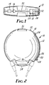
- FIGS 1 and 2 show the top and the front views of a transcutaneous electrical nerve stimulator (TENS) 10.
- the stimulator 10 has a housing 12 which is of a generally flattened disk shape having well rounded edges.
- the flattened disk shape is of slightly eliptical dimension to aid in appearance and to facilitate a hanging-style attachment.
- a power switch 14 At one location on the side edge of the housing 12 is mounted a power switch 14 which may be operator controlled to quickly turn on or off the power to the stimulator.
- An indicator light 16 is also provided, in a preferred embodiment, as an aid to showing the user that power is being supplied to the stimulator 10 and/or that battery power is nearly exhausted.
- the stimulator 10 has two output channels.
- rocker switches 18 and 20 The amplitude of the current pulses supplied by each output channel is controlled by rocker switches 18 and 20, respectively, each mounted on one side edge of the housing 12.
- Rocker switch 18 controls the current amplitude of the stimulation pulse to be delivered by channel 1 of the stimulator 10 while rocker switch 20 controls the current amplitude of the current stimulation pulse supplied by channel 2 of the stimulator 10.
- rocker switches 18 and 20 are located on one lateral hemisphere of housing 12.
- the rocker switch 18 for channel 1 is positioned toward the top of the stimulator 10 while the rocker switch for channel 2 is located in the lower portion of stimulator 10.
- Rocker switch 18 rests in a neutral position when not being operated by the user.
- rocker switch 18 When rocker switch 18 is pushed at end 22, an increase in the current amplitude of the channel 1 stimulation pulse is accomplished. Conversely, pushing rocker switch 18 at end 24 operates to decrease the current amplitude of the channel 1 stimulation pulse. Similarly, rocker switch 20 when pushed at end 26 increases the current amplitude of the channel 2 stimulation pulse. Correpondingly, a push at end 28 decreases the current amplitude. Electrical jacks 30 are provided to individually allow connection of stimulation electrodes to the stimulator 10. A first attachment point 32 is provided on the housing 12 at the top of the stimulator 10. A second attachment point 34 is provided on a side edge of the housing 12 opposite the first attachment point 32. In a preferred embodiment, attachment points 32 and 34 are formed as an attachment bar mounted on housing 12 over a tapered depression in the housing thus forming an unobtrusive channel. A mounting strap may then be passed through said channel and secured to the body or to clothing.
- FIG. 3 illustrates a general block diagram of the electrical circuit 36 required to supply high voltage current output pulses 38 of the stimulator 10.
- battery power 40 is supplied to a switched inductor circuits 42.
- a clock 44 drives a control circuit 46 which in turn supplies a programmable logic block 48 which supplies switching signals 51 to switched inductor circuit 42 for generating a high-voltage signal 52 to be supplied to output stages 54.
- Programmable logic block 48 also supplies timing and amplitude information signals 50 to output stages 54 which then utilizes a high-voltage signal 52 to supply electrical stimulation signal 38.
- Programmable logic block 48 receives external status information 56 and conditionally supplies power to indicator light 16 on a periodic basis. Included in the external status information 56 is the condition of switches 14, 18 and 20 and the voltage level of the battery power supply.
- the block diagram of the electrical circuit 36 illustrated in Figure 3 is general and of the generally perferred electrical circuit of the transcutaneous electrical nerve stimulator 10 of the present invention. It is to be recognized and understood that electrical circuits for use in transcutaneous electrical nerve stimulators are well known in the art. Any of the generally available electrical circuits could be utilized in the transcutaneous electrical nerve stimulator 10 of the present invention.
- the particular block diagram illustrated in Figure 3 is supplied for convenience and no particular engineering skill should be required to obtain or design any one of a number of existing electrical circuits 36 which can be utilized in transcutaneous electrical nerve stimulators 10.
- the transcutaneous electrical nerve stimulator 10 shown and described uses a variety of technics to both improve wearability and to give a visual impression of small size and good asthetics.
- the significant radiusing of the outside edges of housing 12, the angled placement of jacks 30 and the spherically convex shaping of the front and rear surfaces of housing 12 contribute to the desired result.
- the placement on side edges of user control switches 14, 18 and 20 make them less conspicuous while making them easier to operate.
- the asymmetrical placement of power switch 14 as compared to amplitude switches 18 and 20 aids in their location and positive identification by the user even when the stimulator 10 is worn under clothing.
- the rocker switches 18 and 20 permit amplitude to be adjusted in steps.
- rocker switches 18 and 20 Depression of the rocker switches 18 and 20 toward the top of the housing 12 causes an increase in stimulation pulse 38 amplitude while depression toward the bottom of the housing 12 causes a decrease in pulse amplitude.
- rocker switches 18 and 20 rest in a neutral position.
- Rocker switches 18 and 20 are provided with an electronic delay mechanism so that rocker switch depressions of less than 0.5 second only result in a single step change in amplitude.
- step changes will be generated at regular intervals (typically 0.5 seconds) until either stimulation amplitude has been decreased to zero or stimulation amplitude has reached its maximum allowable amplitude.
- a total of 64 steps in current amplitude are provided.
- timing parameters are chosen to permit a precise setting of comfortable stimulation amplitudes by the user.
- Continuous depression of rocker switches 18 or 20 is generally used to rapidly reach the general region of comfortable current amplitudes, while subsequent discrete depressions are designed to provide single step amplitude corrections.
- Rocker switches were chosen for switches 18 and 20 rather than individual increase and decrease buttons to simplify the user interface since only one switch (rather than two) needs to be located for each channel of operation.
- the side edge mounting of rocker switches 18 and 20 minimize the pressure against the skin. The pressure necessary to activate the side-mounted switches 18 and 20 by one finger is easily opposed by fingers of the same hand resting on the opposite side of the stimulator 10. Thus, the forces applied to the rocker switches 18 or 20 are not also directed at tender regions of the body such as the breasts or abdomen.
- rocker switches 18 and 20 are designed to minimize their projection from the side of the housing 12 and, thus, reduce the chance for inadvertent amplitude adjustment as well as being selected for good tactile feedback.
- Housing 12 has two attachment points 32 and 34, top and bottom, respectively.
- These attachment points 32 and 34 consist of "channels" or depressions in the case over which a bar is mounted to the housing permitting the use of various ribbons or straps as attachment devices.
- These ribbon attachments may consist of a self-fastening material such as a hook and loop fastener or elastic materials.
- One of these attachment mechanisms is illustrated in Figure 4.
- the stimulator 10 is hung from the first attachment point 32 by a strap 58 which passes around the center portion of a bra 60.
- An alternative bra attachment mechanism is illustrated in Figure 5 in which the stimulator 10 is again held by a strap 58 passed around the central portion of a bra 60 but this time made more secure by having strap 58 pass through both top attachment point 32 and bottom attachment point 34.
- FIGs 6 and 7 Two examples of waist attachments are illustrated in Figures 6 and 7.
- the stimulator 10 is secured to a belt 62 by hook-and-loop strap 64 passing through first attachment point 32 and second attachment point 34.
- the belt 62 is secured around the waist of the wearer by a hook-and-loop fastener portion 66 fed through a D-ring 68.
- Figure 7 shows a similar arrangement in which the stimulator 10 is secured to belt 62 by having belt pass through first attachment point 32 and second attachment point 34.
- Belt 62 is secured around the waist by a swimsuit closure hook 70.
- Belt 62 may be adjusted by a slide 72. It is preferred that the belt 62 be constructed from an approximately one-half inch (1.27 centimeters) stretch soft bra strap material.
Landscapes
- Health & Medical Sciences (AREA)
- Life Sciences & Earth Sciences (AREA)
- Biomedical Technology (AREA)
- Biophysics (AREA)
- Heart & Thoracic Surgery (AREA)
- Engineering & Computer Science (AREA)
- Pain & Pain Management (AREA)
- Nuclear Medicine, Radiotherapy & Molecular Imaging (AREA)
- Radiology & Medical Imaging (AREA)
- Animal Behavior & Ethology (AREA)
- General Health & Medical Sciences (AREA)
- Public Health (AREA)
- Veterinary Medicine (AREA)
- Electrotherapy Devices (AREA)
Claims (9)
- Stimulateur transcutané des nerfs (10), comprenant des moyens électriques pour engendrer un ensemble prédéterminé de signaux électriques de stimulation pouvant être appliqués à un corps, et capables d'engendrer ledit signal électrique de stimulation avec une amplitude qui peut être modifiée ;un boîtier (12) contenant lesdits moyens électriques, qui comporte un premier contact ( 18) monté sur un bord latéral dudit boîtier (12) et raccordé auxdits moyens électriques, et qui comporte un deuxième contact (14) monté sur un bord latéral dudit boîtier (12) et raccordé auxdits moyens électriques, ledit deuxième contact (14) commandant l'alimentation desdits moyens électriques ;
caractérisé en ce que :
ledit boîtier (12) est en forme de disque sensiblement aplati à bords bien arrondis ; et
ledit premier contact (18) est un contact basculant qui agit pour augmenter ladite amplitude lorsque ledit premier contact basculant (18) est poussé par un opérateur dans une première direction (24), et qui agit pour diminuer ladite amplitude lorsque ledit premier contact basculant (18) est poussé par un opérateur dans la direction opposée (22), ledit premier contact basculant (18) réglant l'intensité dudit signal électrique de stimulation. - Stimulateur électrique transcutané des nerfs (10) suivant la revendication 1, dans lequel les dits moyens électriques comprennent une pluralité de canaux de stimulation indépendants engendrant chacun un ensemble prédéterminé de signaux électriques de stimulation, dans lequel ledit premier contact (18) commande les signaux électriques de stimulation d'un de ladite pluralité de canaux de stimulation indépendants, et qui comprend en outre au moins un autre contact basculant (20) monté sur un bord dudit boîtier (12) et raccordé auxdits moyens électriques pour régler l'amplitude dudit signal électrique d'un autre de ladite pluralité de canaux de stimulation d'une manière similaire à la manière dont ledit premier contact basculant (18) règle l'amplitude de son signal associé dudit ensemble de signaux électriques de stimulation.
- Stimulateur électrique transcutané des nerfs (10) suivant la revendication 2, dans lequel le dit premier contact (18) et ledit autre contact sont montés sur le bord latéral du même hémisphère latéral dudit boîtier (12).
- Stimulateur électrique transcutané des nerfs (10) suivant la revendication 1, dans lequel le dit deuxième contact (14) est un contact coulissant, et dans lequel ledit premier contact (18) et ledit deuxième contact (14) sont montés sur des bords latéraux opposés dudit boîtier (12).
- Stimulateur électrique transcutané des nerfs (10) suivant la revendication 1, dans lequel le dit premier contact (18), lorsqu'on le pousse momentanément, agit pour faire varier ladite amplitude d'un d'une pluralité de paliers discrets et, lorsqu'on le pousse de façon continue pendant au moins une demiseconde, il agit pour faire varier ladite amplitude séquentiellement suivant ladite pluralité dedits paliers discrets.
- Stimulateur électrique transcutané des nerfs (10) suivant la revendication 1, dans lequel le dit boîtier (12) est de forme légèrement elliptique.
- Stimulateur électrique transcutané des nerfs (10) suivant la revendication 6, dans lequel ledit boîtier (12) comporte un premier point d'attache de bande (32) le long dudit bord latéral dudit disque aplati, à l'endroit du sommet désiré dudit stimulateur (10).
- Stimulateur électrique transcutané des nerfs (10) suivant la revendication 7, dans lequel ledit boîtier (12) comporte un deuxième point d'attache de bande ( 34) le long dudit bord latéral dudit disque aplati, à l'opposé dudit premier point d'attache de bande (32).
- Stimulateur électrique transcutané des nerfs (10) suivant la revendication 8, dans lequel ledit premier point d'attache de bande (32) et ledit deuxième point d'attache de bande (34) comprennent chacun une barrette de fixation montée sur ledit boîtier (12) au-dessus d'un évidement incliné ménagé dans le dit boîtier (12).
Applications Claiming Priority (2)
| Application Number | Priority Date | Filing Date | Title |
|---|---|---|---|
| US42291 | 1987-04-24 | ||
| US07/042,291 US4803986A (en) | 1987-04-24 | 1987-04-24 | Ergonometric transcutaneous electrical nerve stimulator |
Publications (3)
| Publication Number | Publication Date |
|---|---|
| EP0288260A2 EP0288260A2 (fr) | 1988-10-26 |
| EP0288260A3 EP0288260A3 (en) | 1989-02-08 |
| EP0288260B1 true EP0288260B1 (fr) | 1993-05-26 |
Family
ID=21921081
Family Applications (1)
| Application Number | Title | Priority Date | Filing Date |
|---|---|---|---|
| EP88303547A Expired - Lifetime EP0288260B1 (fr) | 1987-04-24 | 1988-04-20 | Stimulateur électrique ergonométrique par voie transcutanée de nerfs |
Country Status (7)
| Country | Link |
|---|---|
| US (1) | US4803986A (fr) |
| EP (1) | EP0288260B1 (fr) |
| JP (1) | JPS63279855A (fr) |
| AU (1) | AU603649B2 (fr) |
| CA (1) | CA1321242C (fr) |
| DE (1) | DE3881267T2 (fr) |
| HK (1) | HK116894A (fr) |
Families Citing this family (27)
| Publication number | Priority date | Publication date | Assignee | Title |
|---|---|---|---|---|
| AU607977B2 (en) * | 1987-04-24 | 1991-03-21 | Minnesota Mining And Manufacturing Company | Biological tissue stimulator with time-shared logic driving output timing and high voltage step-up circuit |
| US4996987A (en) * | 1989-05-10 | 1991-03-05 | Therapeutic Technologies Inc. | Power muscle stimulator |
| US5109863A (en) * | 1989-10-26 | 1992-05-05 | Rutgers, The State University Of New Jersey | Noninvasive diagnostic system for coronary artery disease |
| US5048522A (en) * | 1990-04-13 | 1991-09-17 | Therapeutic Technologies, Inc. | Power muscle stimulator |
| US5797854A (en) * | 1995-08-01 | 1998-08-25 | Hedgecock; James L. | Method and apparatus for testing and measuring current perception threshold and motor nerve junction performance |
| US5607461A (en) * | 1995-10-20 | 1997-03-04 | Nexmed, Inc. | Apparatus and method for delivering electrical stimulus to tissue |
| US6193668B1 (en) | 1997-11-10 | 2001-02-27 | Medacoustics, Inc. | Acoustic sensor array for non-invasive detection of coronary artery disease |
| US6278890B1 (en) | 1998-11-09 | 2001-08-21 | Medacoustics, Inc. | Non-invasive turbulent blood flow imaging system |
| US6314325B1 (en) | 1998-04-07 | 2001-11-06 | William R. Fitz | Nerve hyperpolarization method and apparatus for pain relief |
| US6014588A (en) * | 1998-04-07 | 2000-01-11 | Fitz; William R. | Facet joint pain relief method and apparatus |
| US7286893B1 (en) | 1998-06-30 | 2007-10-23 | Jyoti Mazumder | Tailoring residual stress and hardness during direct metal deposition |
| US6937921B1 (en) | 1998-06-30 | 2005-08-30 | Precision Optical Manufacturing (Pom) | Production of smart dies and molds using direct metal deposition |
| US6410105B1 (en) | 1998-06-30 | 2002-06-25 | Jyoti Mazumder | Production of overhang, undercut, and cavity structures using direct metal depostion |
| US6122564A (en) * | 1998-06-30 | 2000-09-19 | Koch; Justin | Apparatus and methods for monitoring and controlling multi-layer laser cladding |
| US6261237B1 (en) | 1998-08-20 | 2001-07-17 | Medacoustics, Inc. | Thin film piezoelectric polymer sensor |
| US6445955B1 (en) * | 1999-07-08 | 2002-09-03 | Stephen A. Michelson | Miniature wireless transcutaneous electrical neuro or muscular-stimulation unit |
| US6282443B1 (en) | 1999-12-14 | 2001-08-28 | Woodside Biomedical, Inc. | Method of treatment of dysmenorrhea or relieving menstrual cramps |
| US20020165634A1 (en) * | 2000-03-16 | 2002-11-07 | Skszek Timothy W. | Fabrication of laminate tooling using closed-loop direct metal deposition |
| DE10155551B4 (de) * | 2001-11-12 | 2005-02-10 | Manou Prof. Dr. Komeyli | Vorrichtung zur transkutanen elektrischen Nervenstimulation |
| US6830550B2 (en) | 2002-06-25 | 2004-12-14 | James Lee Hedgecock | Stair step voltage actuated measurement method and apparatus |
| US7139633B2 (en) * | 2002-08-29 | 2006-11-21 | Jyoti Mazumder | Method of fabricating composite tooling using closed-loop direct-metal deposition |
| US20040059385A1 (en) * | 2002-09-25 | 2004-03-25 | Yu Tsung I. | Low frequency assistor for electric-stimulating breast acupuncture point portions of a human body |
| US8159777B2 (en) * | 2008-06-19 | 2012-04-17 | Apple Inc. | Portable electronic device with multipurpose hard drive circuit board |
| US9095994B2 (en) | 2011-08-09 | 2015-08-04 | GM Global Technology Operations LLC | Method for applying variable magnetic properties to a induction heated tool face and manufacturing parts using the tool |
| US10463854B2 (en) | 2015-02-24 | 2019-11-05 | Elira, Inc. | Systems and methods for managing symptoms associated with dysmenorrhea using an electro-dermal patch |
| WO2017075359A2 (fr) * | 2015-10-29 | 2017-05-04 | Elira Therapeutics Llc | Systèmes et procédés de gestion de symptômes associés à la dysménorrhée à l'aide d'un patch électro-dermique |
| UY36935A (es) | 2016-03-31 | 2017-11-30 | Medecell S A | Proceso para establecer un protocolo de electroestimulación para el control de dolores pélvicos, y el respectivo equipo portátil de electroestimulación para el control de dolores pélvicos utilizando el referido protocolo |
Family Cites Families (11)
| Publication number | Priority date | Publication date | Assignee | Title |
|---|---|---|---|---|
| US30028A (en) * | 1860-09-11 | Griddle | ||
| US447857A (en) * | 1891-03-10 | Galvanic apparatus for the human body | ||
| US3025858A (en) * | 1956-10-19 | 1962-03-20 | Relaxacizor Inc | Ambulatory electrical muscle stimulating device |
| CH389114A (de) * | 1961-05-13 | 1965-03-15 | Hochstrasser Peter | Elektrisches Reizgerät zur Erzeugung von Muskel-Reizimpulsen |
| US3718142A (en) * | 1971-04-23 | 1973-02-27 | Medtronic Inc | Electrically shielded, gas-permeable implantable electro-medical apparatus |
| USRE30028E (en) | 1973-07-12 | 1979-06-12 | Coratomic, Inc. | Heart pacer |
| US4033356A (en) * | 1975-08-20 | 1977-07-05 | Hakuju Institute For Health Science Co., Ltd. | Apparatus for therapeutical treatment and stimulation of muscles by low-frequency oscillating electric current |
| US4324253A (en) * | 1977-01-28 | 1982-04-13 | Greene Ronald W | Transcutaneous pain control and/or muscle stimulating apparatus |
| US4121594A (en) * | 1977-09-26 | 1978-10-24 | Med General, Inc. | Transcutaneous electrical nerve stimulator |
| US4770328A (en) * | 1982-12-16 | 1988-09-13 | Medtronic, Inc. | Tissue stimulator casing |
| US4542753A (en) * | 1982-12-22 | 1985-09-24 | Biosonics, Inc. | Apparatus and method for stimulating penile erectile tissue |
-
1987
- 1987-04-24 US US07/042,291 patent/US4803986A/en not_active Expired - Lifetime
-
1988
- 1988-03-24 AU AU13576/88A patent/AU603649B2/en not_active Ceased
- 1988-04-14 CA CA000564100A patent/CA1321242C/fr not_active Expired - Fee Related
- 1988-04-20 DE DE88303547T patent/DE3881267T2/de not_active Expired - Fee Related
- 1988-04-20 EP EP88303547A patent/EP0288260B1/fr not_active Expired - Lifetime
- 1988-04-22 JP JP63098482A patent/JPS63279855A/ja active Pending
-
1994
- 1994-10-27 HK HK116894A patent/HK116894A/en not_active IP Right Cessation
Non-Patent Citations (1)
| Title |
|---|
| Journal of Clinical Oncology, vol.3, no.3, March 1985, pages 407-414 * |
Also Published As
| Publication number | Publication date |
|---|---|
| CA1321242C (fr) | 1993-08-10 |
| US4803986A (en) | 1989-02-14 |
| AU603649B2 (en) | 1990-11-22 |
| HK116894A (en) | 1994-11-04 |
| AU1357688A (en) | 1988-10-27 |
| JPS63279855A (ja) | 1988-11-16 |
| EP0288260A3 (en) | 1989-02-08 |
| DE3881267D1 (de) | 1993-07-01 |
| EP0288260A2 (fr) | 1988-10-26 |
| DE3881267T2 (de) | 1993-11-11 |
Similar Documents
| Publication | Publication Date | Title |
|---|---|---|
| EP0288260B1 (fr) | Stimulateur électrique ergonométrique par voie transcutanée de nerfs | |
| US4690144A (en) | Wireless transcutaneous electrical tissue stimulator | |
| US4381012A (en) | Electrode placement device | |
| US9421358B2 (en) | External, head-worn electrical stimulator for treating headache conditions | |
| CA1173113A (fr) | Automatisme de mise en place d'une electrode | |
| EP1194181B1 (fr) | Unite miniature sans fil de neurostimulation ou de stimulation musculaire electrique transcutanee | |
| EP1620169B1 (fr) | Appareil permettant de soumettre le systeme neuromusculaire a un courant electrique | |
| US5099829A (en) | Massage device good for eyes | |
| US6002965A (en) | Self applied device and method for prevention of deep vein thrombosis | |
| US9352157B2 (en) | Intra-oral balance device based on palatal stimulation | |
| US5922012A (en) | Low-frequency electrotherapeutic device having three or more electrodes for generating flexible stimulation patterns | |
| EP0033643B1 (fr) | Appareil de stimulation électrique de l'oeil | |
| US20030088294A1 (en) | Movement timing stimulator | |
| HUT60931A (en) | Device for stimulating /eliciting/ the operation of the hand | |
| GB2123698A (en) | Biological electrical stimulators | |
| US20190143114A1 (en) | Adjustable TMJ Headband | |
| US20150190650A1 (en) | Flexible eye mask | |
| JP2017192545A (ja) | 低周波治療器 | |
| KR101749175B1 (ko) | 저주파 치료기 | |
| CN223586418U (zh) | 治疗或预防头痛的腕戴设备 | |
| CN121534314A (zh) | 一种神经电刺激系统及方法 | |
| KR200248138Y1 (ko) | 저주파 근육 운동기 | |
| US20240382744A1 (en) | Wearable electrode device having magnetic connectors | |
| US20050049654A1 (en) | Ultralight pre-programmed microprocessor based electrotherapy technology | |
| JP3027590B2 (ja) | 低周波治療器 |
Legal Events
| Date | Code | Title | Description |
|---|---|---|---|
| PUAI | Public reference made under article 153(3) epc to a published international application that has entered the european phase |
Free format text: ORIGINAL CODE: 0009012 |
|
| AK | Designated contracting states |
Kind code of ref document: A2 Designated state(s): DE FR GB |
|
| PUAL | Search report despatched |
Free format text: ORIGINAL CODE: 0009013 |
|
| RHK1 | Main classification (correction) |
Ipc: A61N 1/32 |
|
| AK | Designated contracting states |
Kind code of ref document: A3 Designated state(s): DE FR GB |
|
| 17P | Request for examination filed |
Effective date: 19890711 |
|
| 17Q | First examination report despatched |
Effective date: 19911112 |
|
| GRAA | (expected) grant |
Free format text: ORIGINAL CODE: 0009210 |
|
| AK | Designated contracting states |
Kind code of ref document: B1 Designated state(s): DE FR GB |
|
| REF | Corresponds to: |
Ref document number: 3881267 Country of ref document: DE Date of ref document: 19930701 |
|
| ET | Fr: translation filed | ||
| PLBE | No opposition filed within time limit |
Free format text: ORIGINAL CODE: 0009261 |
|
| STAA | Information on the status of an ep patent application or granted ep patent |
Free format text: STATUS: NO OPPOSITION FILED WITHIN TIME LIMIT |
|
| 26N | No opposition filed | ||
| PGFP | Annual fee paid to national office [announced via postgrant information from national office to epo] |
Ref country code: FR Payment date: 19950313 Year of fee payment: 8 |
|
| PG25 | Lapsed in a contracting state [announced via postgrant information from national office to epo] |
Ref country code: FR Effective date: 19961227 |
|
| REG | Reference to a national code |
Ref country code: FR Ref legal event code: ST |
|
| PGFP | Annual fee paid to national office [announced via postgrant information from national office to epo] |
Ref country code: GB Payment date: 19970326 Year of fee payment: 10 |
|
| PGFP | Annual fee paid to national office [announced via postgrant information from national office to epo] |
Ref country code: DE Payment date: 19980326 Year of fee payment: 11 |
|
| PG25 | Lapsed in a contracting state [announced via postgrant information from national office to epo] |
Ref country code: GB Free format text: LAPSE BECAUSE OF NON-PAYMENT OF DUE FEES Effective date: 19980420 |
|
| GBPC | Gb: european patent ceased through non-payment of renewal fee |
Effective date: 19980420 |
|
| PG25 | Lapsed in a contracting state [announced via postgrant information from national office to epo] |
Ref country code: DE Free format text: LAPSE BECAUSE OF NON-PAYMENT OF DUE FEES Effective date: 20000201 |