EP0288329A1 - Vorrichtung zur seitlichen Beleuchtung eines vor einem Hintergrund gestellten Objektes sowie die Beleuchtung dieses Hintergrundes zum Beispiel während einer photographischen, kinematographischen oder ähnlichen Aufnahme - Google Patents
Vorrichtung zur seitlichen Beleuchtung eines vor einem Hintergrund gestellten Objektes sowie die Beleuchtung dieses Hintergrundes zum Beispiel während einer photographischen, kinematographischen oder ähnlichen Aufnahme Download PDFInfo
- Publication number
- EP0288329A1 EP0288329A1 EP88400316A EP88400316A EP0288329A1 EP 0288329 A1 EP0288329 A1 EP 0288329A1 EP 88400316 A EP88400316 A EP 88400316A EP 88400316 A EP88400316 A EP 88400316A EP 0288329 A1 EP0288329 A1 EP 0288329A1
- Authority
- EP
- European Patent Office
- Prior art keywords
- panels
- background
- assembly
- reflective
- subject
- Prior art date
- Legal status (The legal status is an assumption and is not a legal conclusion. Google has not performed a legal analysis and makes no representation as to the accuracy of the status listed.)
- Withdrawn
Links
- 238000005286 illumination Methods 0.000 title 2
- 239000007787 solid Substances 0.000 claims abstract description 4
- 230000003100 immobilizing effect Effects 0.000 claims 2
- 239000000243 solution Substances 0.000 description 4
- 230000000694 effects Effects 0.000 description 3
- 239000000463 material Substances 0.000 description 3
- 230000008901 benefit Effects 0.000 description 2
- 239000011248 coating agent Substances 0.000 description 2
- 238000000576 coating method Methods 0.000 description 2
- 230000000295 complement effect Effects 0.000 description 2
- 238000000034 method Methods 0.000 description 2
- 241000826860 Trapezium Species 0.000 description 1
- 240000008042 Zea mays Species 0.000 description 1
- 230000008859 change Effects 0.000 description 1
- 238000010276 construction Methods 0.000 description 1
- 230000008878 coupling Effects 0.000 description 1
- 238000010168 coupling process Methods 0.000 description 1
- 238000005859 coupling reaction Methods 0.000 description 1
- 229940082150 encore Drugs 0.000 description 1
- 238000001746 injection moulding Methods 0.000 description 1
- 238000009434 installation Methods 0.000 description 1
- 238000004519 manufacturing process Methods 0.000 description 1
- 239000002184 metal Substances 0.000 description 1
- 230000004048 modification Effects 0.000 description 1
- 238000012986 modification Methods 0.000 description 1
- 230000008569 process Effects 0.000 description 1
- 230000009467 reduction Effects 0.000 description 1
- 238000007493 shaping process Methods 0.000 description 1
- 238000003856 thermoforming Methods 0.000 description 1
- 238000007666 vacuum forming Methods 0.000 description 1
- 239000002023 wood Substances 0.000 description 1
Images



Classifications
-
- G—PHYSICS
- G03—PHOTOGRAPHY; CINEMATOGRAPHY; ANALOGOUS TECHNIQUES USING WAVES OTHER THAN OPTICAL WAVES; ELECTROGRAPHY; HOLOGRAPHY
- G03B—APPARATUS OR ARRANGEMENTS FOR TAKING PHOTOGRAPHS OR FOR PROJECTING OR VIEWING THEM; APPARATUS OR ARRANGEMENTS EMPLOYING ANALOGOUS TECHNIQUES USING WAVES OTHER THAN OPTICAL WAVES; ACCESSORIES THEREFOR
- G03B15/00—Special procedures for taking photographs; Apparatus therefor
- G03B15/02—Illuminating scene
- G03B15/06—Special arrangements of screening, diffusing, or reflecting devices, e.g. in studio
Definitions
- the present invention relates to a device intended to ensure the lighting of this background itself, for example during a shooting of this subject by photography, cinematography or the like.
- this device is also capable of being used for similar use around an object during the presentation of the latter in a display case.
- One of the solutions currently applied to obtain a satisfactory result consists in using, in addition to a main source of lighting arranged in front of the subject to be photographed, several additional sources of light distributed around this subject. Some of these are provided on the sides to illuminate the corresponding subject laterally in order to give more relief. For a similar reason, another additional light source is usually provided on the top.
- Another solution currently used is to have several independent reflection panels around the subject to be photographed. It is then necessary to provide different individual panels of this kind arranged at various appropriate points in order to illuminate the background used as well as the sides of the subject, and possibly the upper part thereof.
- the method of using individual reflection panels cannot be applied in a certain number of cases, for example for shooting a small still life.
- the panels usually used would be too large to be able to be arranged around the subject to be photographed.
- the mounting and adjustment of such panels raise difficulties, because there are no supports making it possible to easily adjust their orientation and to keep them in the desired position.
- the present invention aims to make a device of a completely different design which is intended to allow obtaining a background of good quality and optimum lighting of the subject without the need to have recourse to additional light sources or even individual reflection panels arranged separately around the subject to be photographed.
- this device is also designed so as to further improve the lighting of the subject to be photographed and of the background placed behind it.
- the device according to the invention essentially consists of a series of straight or curved or faceted reflective panels, attached to a solid central base, full or hollowed out or attached to one another around a corresponding free surface. at the bottom of the assembly, these reflective panels being arranged in raised positions and inclined relative to the plane of the bottom of the assembly or of the bottom panel, in orientations such that these panels are capable of reflecting, towards the subject to be photograph, as well as towards the bottom of the assembly, the light emitted by a frontal source of light, the assembly having a generally concave shape.
- the background provided and the subject placed in front of it are illuminated in optimum conditions by light rays directed all around them and which actually come from a single source of light, in this case the main source of light. lighting placed near the camera facing the subject to be photographed.
- the present device comprises three reflective panels arranged around a bottom panel or a free surface corresponding to the bottom of the assembly, namely: a reflective panel intended to be placed upwards, and other reflective panels intended to be placed on either side of the subject to be photographed.
- the present device comprises two reflective panels arranged on either side of a bottom panel serving as their support.
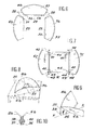
- the device according to the invention comprises several reflective panels attached one after the other, around a frame 1 to which they are integral.
- This frame which materializes the plane of the bottom of the assembly, surrounds a free surface 2 of square or other outline.
- this frame is intended to be arranged vertically against a wall or fixed on any other support.
- this frame is provided with clamps 3 or other suitable fixing means making it possible to fix, in front of this frame, an element intended to constitute the actual background of a shot, for example a sheet 4 of paper having the desired characteristics.
- the frame thus provided also includes means making it possible to fix it against a wall or on any suitable support.
- this frame can simply have two holes 5 intended to receive fixing nails.
- a fastening system can be provided for making a attachment to such a support.
- the frame 1 On each of these lateral sides, the frame 1 carries two reflecting panels 6 and 7. These panels are straightened and inclined relative to the plane of the bottom of the assembly, that is to say the plane of the frame 1. Relative in this plane, if the angles of the panels are adjustable with respect to the central background, they are able to reflect, either only towards the actual background 4, or on the background 4 as well as on the sides of the subject to be photographed (for example the head 22 of a person), i.e. only towards the sides of the subject, the light emitted by a source of light 9 arranged in front of this subject and this, at some distance above the camera used 10.
- the whole has a generally concave shape, or even the shape of a sort of bowl with inclined side walls, which would be open on one of its sides, in this case its lower side.
- the surface of the side panels 6 and 7 is treated so that they have suitable light reflection characteristics.
- these panels may advantageously include a metallized surface.
- instead of these these panels could be provided with a coating of white color, which would be less advantageous.
- the edge of the frame 1, intended to be placed upwards, carries another reflecting panel 8.
- This upper reflecting panel is tilted forward to form a determined angle with respect to the plane of the frame 1, in a similar manner to the side panels 6 and 7.
- this panel is advantageously curved. The arrangement thus provided is such that this panel, which is placed above the subject to be photographed, is thus able to reflect, both on top of this subject and towards the background proper 4, the light which comes from the front light source 9.
- the upper panel 8 is connected to the side panels 6 by intermediate facets 11 and 12 separated by fold lines.
- All of the different parts thus provided for in the present device can be constituted by a single piece in one piece, the particular shape of which is then obtained by any suitable process, for example by injection molding, or by thermoforming or vacuum forming. when this part is made of plastic.
- this piece can also be made in metal by stamping or by application of any other suitable shaping process.
- this unique piece could also be made of any other suitable material, for example: wood, etc.
- the various parts of the present device can also be constituted by separate parts assembled together at the location of their junction lines.
- Figure 4 shows such an embodiment.
- the frame 1 is replaced by a bottom panel 1a, which is full.
- the reflective panels on each side they consist of a part 13 forming the two corresponding panels 6a and 7a.
- On its edge intended to be fixed on the corresponding edge of the bottom panel 1a each of these parts 13 has a marginal strip 14 which makes a determined angle with respect to the panels 6a and 7a so that it can be fixed flat on the panel of background 1a.
- This fixing is ensured by additional press studs 15 provided on one and the other of the two corresponding parts.
- the panels 6a and 7a are kept inclined relative to the bottom panel 1a, and this in the desired orientation to ensure the reflection of light under the conditions described above.
- the upper reflecting panel 8a of this device is constituted by a separate part 16 also forming facets 11a and 12a, provided at the ends of this flap.
- this piece 16 has a marginal strip 17 intended to be fixed on the upper edge of the bottom panel 1a as well as on the upper edge of these two side pieces 13. This strip therefore forms an angle determined with respect to the panel 8a as well as with respect to the end facets 11a so that this panel and these facets are kept in the desired inclination when the part 16 is fixed to the bottom panel 1a.
- This fixing can be carried out by means of additional press studs 18 or by any other suitable means.
- the solution thus provided in the embodiment according to FIG. 4 makes it possible to keep the device in several separate pieces which can be folded flat when this device is not used, as well as during its storage and transport before being put on sale. . This therefore has the advantage of allowing a considerable reduction in size during this time.
- the bottom panel 1a is not hollowed out so that it can by itself constitute a suitable background for photographic shooting, its surface being chosen or treated accordingly. To this end, it may have a white coating or be made of white plastic. However, the panel 1a can also be provided with fixing clips 3 at its upper part in order to be able to bring a removable bottom element, for example a sheet of paper 4 as in the previous case.
- the panel 8a which has a curved shape, can consist of a flat sheet of flexible material capable of being easily shaped, folding grooves can advantageously be provided.
- this panel can also be constituted by a part initially shaped or molded into the desired shape.
- the present device is more specifically intended to be used for producing both a background behind a determined subject and the optimum lighting thereof when taking a picture of this subject.
- Figure 2 illustrates the case of making a photographic portrait.
- the device according to the invention is placed behind the head 22 of the subject to be photographed, the frame 1 of the background being arranged in an essentially vertical position.
- the reflective upper panel 8 is placed above the subject's head, while the lateral reflective panels 6 and 7 are placed on either side of this head.
- certain light rays, which come from the front light source 9 are reflected by the side panels 6 and 7 on the bottom 4 proper.
- Other light rays coming from this same light source are reflected by the upper panel 8 on the top of the subject's head 22 as well as on the background 4. Under these conditions the head of the subject to be photographed is lit all around it. and it kind of "bathes" in the light.
- the background 4 it is itself perfectly lit behind the subject's head, which avoids the existence of drop shadows due to the subject's head, as would have been the case without the various reflective panels 6 , 7 and 8 of the device according to the invention.
- the various arrows F shown in FIG. 5 illustrate the way in which the light rays are returned by the various reflecting panels all around the head 22 of the subject and towards the background 4 placed behind this head.
- this subject it should be noted that due to successive reflections of the light rays, there is somehow an increase in the amount of light received by the subject at photograph as well as from the background 4.
- FIG. 3 illustrates the use of the device according to the invention for the photography of objects 23 of small dimensions arranged on a tablet 25 or the like.
- the present device is fixed vertically above this tablet.
- an attached sheet 4a is then placed, intended to constitute the bottom itself and which has a length sufficient to also extend above the shelf 25, as shown in Figure 3.
- This gives a continuous background which extends both behind the objects 23 to be photographed and below them.
- the camera 10 and the front light source 9 are then installed in front of the objects to be photographed in a similar manner to that provided in the case illustrated in FIG. 2. same advantageous effects with regard to the lighting of the background 4a and that of the objects to be photographed.
- the design of the device according to the invention allows the shots to be taken by an unqualified operator. Indeed, there is no adjustment to be made for the taking of identity portraits since the various reflective panels 6, 7 and 8 are, by construction, capable of being fixed beforehand in the exact positions desired to obtain an optimum result. However, for portraits with more sought-after lighting, the operator can adjust the tilt of the reflective panels.
- the side panels 6-7 or 6a-7a can optionally carry additional reflective shutters 19 and 20, as shown for some of them in FIG. 4. These additional shutters can be fixed permanently or on the contrary so removable to be used or not depending on the case.
- the arrangement of these panels and panels 6 can advantageously be such that the orientation of these components is adjustable at will, for example by articulation along their line of junction with the panels, appropriate immobilization means. being planned.
- FIG. 6 shows another embodiment of the device according to the invention.
- this device consists of three reflecting panels 6b, 7b and 8b which are intended to be assembled around a free surface of square or rectangular section corresponding to the actual background of the photograph to be produced.
- the assembly can be arranged, either against a wall or other vertical wall, or fixed on a foot, by placing the panel 8b upwards, while the panels 6b and 7b are arranged on both sides.
- the bottom itself can be constituted by a sheet of paper 4 or 4a placed between these various panels.
- the lower edge of the upper panel 8b is provided with clips 3b allowing the fixing of such a sheet of paper or the like.
- the three panels 6b, 7b and 8b have a contour such that after assembly they are arranged in planes inclined relative to the plane of the bottom of the assembly.
- the outline of each of these panels has the general shape of a trapezium whose large base 27 is directed outwards and advantageously has a curved shape. If these three panels are not preassembled, at the place of their junction lines, means for assembling them are provided such as snaps 28, or other complementary assembly members, which are arranged on the facing edges.
- each of the reflecting panels carries a rectilinear strip 29 attached to the corresponding panel by a line of articulation 30 also serving as a hinge.
- these three strips 29 are arranged in the plane of the bottom of the assembly and they constitute, so to speak, a frame for this bottom. Press studs 31 allow these strips to be assembled together at the corners of this frame.
- the device thus formed can be placed on a support leg or against a wall or other vertical wall to be used in the same way as the devices shown in Figures 2 and 3 for photographing the head of a person or photographing a 'specified objects.
- it can also be used in the manner shown in FIG. 8.
- the three reflective panels 6b, 7b and 8b are attached one after the other without interruption to form in a way a pyramid trunk placed on a table 35 serving to support the objects 23 to be photographed, the latter being arranged in the space left free between the three reflecting panels 6b, 7b and 8b.
- the photographic background of the assembly can be constituted by the upper surface of the table 35 if this surface is suitable.
- FIGs 9 and 10 illustrate a detail of an alternative embodiment of the device shown in Figure 6.
- each of the side panels 6b and 7b is joined to the upper panel 8b by means allowing a modification of the orientation of these side panels.
- the upper end of each side panel 6b or 7b comprises an articulated flap 36 which is attached to a similar flap 37 carried by the upper reflecting panel 8b.
- These two components are joined by a bolt 38 which is carried by one of these components and can slide in a curved slot 39 of the other component. This therefore makes it possible to modify the inclination of each side panel 6b or 7b to place it in a more or less straightened position relative to the plane of the bottom of the assembly.
- a nut 40 screwed on the bolt 38 secures each side panel in the desired orientation.
- FIG. 7 represents yet another embodiment of the device according to the invention.
- the corresponding device simply comprises two reflecting panels 6c and 7c which are analogous to the panels 6b and 7b of the embodiment according to FIG. 6.
- this device is fixed on a bottom panel 1c which is intended to serve as support for the two side panels 6c and 7c, these being fixed on the corresponding edges of this bottom panel by means of assembly snaps 41.
- each end of these side panels carries an articulated flap 42 provided with an articulated base 43.
- this base is provided with a press button 44 intended to be coupled with a complementary member 45 carried by the bottom 1c .
- a complementary member 45 carried by the bottom 1c .
- any other appropriate means could be provided to perform this function, for example brackets or other support members arranged outside.
- FIGS. 11 to 13 represent a variant of the embodiment according to FIG. 6.
- the device also consists of three reflecting panels 6d, 7d and 8d comprising an internal border 29 with respect to which each is articulated by a fold line 30.
- the two side panels 6d and 7d are permanently attached, at one or the other end, of the upper panel 8d by means of a hinge pin 46.
- they are attached by a press button 47 to small intermediate flaps 48 carried by both ends of the upper panel 8d. It suffices to dismantle the press studs 47 in order to be able to fold the three panels 6d and 7d one above the other. However, the small intermediate flaps could possibly be eliminated.
- the two side panels 6d and 7d are joined by a rigid crosspiece 49, one end of which is permanently attached to one of these panels by means of a hinge pin 50.
- a hinge pin 50 As for its end opposite she is removably attached to the other side panel, by means of a press button 51.
- This frame comprises another horizontal crosspiece 52 disposed at mid-height. This consists of two strips 53 removably secured by screws and nuts 54 in the middle of the assembly. The screws and nuts provided at this location also secure this crosspiece with a vertical upright 55 whose upper end 56 extends behind the upper panel 8d. This end is bent at the desired angle taking account of the inclination provided for this panel and it is fixed to this panel in a removable manner by means of screw and nut 57.
- the two bars 53 constituting the central crosspiece 52 are detachably fixed to the back of the edges 29 of the side panels 6d and 7d, and this by means of screws and nuts 58.
- the ends 59 of these bars extend behind both side panels. However, they are bent at an angle ⁇ which corresponds to the maximum deployment angle provided for the side panels.
- a cable 60 or the like passing through a locking collar 61 carried by the end 59 of the corresponding bar 53.
- the upright 55 of the framework thus provided carries at the rear a tab 62 by means of which this frame can be fixed on a suitable support, for example the upper end of a folding or telescopic foot 63 of the type used in photography.
- the device thus constituted can be used in the same way as the devices shown in FIGS. 2 and 3 for photographing the head of a subject or photographing specific objects.
- the device according to the invention can therefore comprise a more or less large number of reflective panels arranged around the surface which is intended to materialize the bottom of the assembly, these panels being being attached directly to each other. following the others (case of FIGS. 1 to 6), either connected indirectly via a bottom panel (case of FIG. 7).
- the device according to the invention may comprise a bottom panel (case of FIGS. 4 and 7), or else be devoid of any bottom panel (case of FIGS. 1 and 6), a frame 1 then being advantageously provided in the bottom plane of the assembly without this being essential.
- This frame can then carry a member for fixing it on a foot serving as support for the assembly.
- the assembly constituted by the present device always has a generally concave shape, or the shape of a sort of bowl with inclined walls which would be open on one or more of its sides.
- the use of the device according to the invention is not limited to the production of a background and a reflective frame behind and around a determined subject during a photographic shooting or similar. Indeed this device can also be used as a background and reflective frame behind and around certain objects in an exhibition window, for example a shop window, one or more light sources being provided facing the assembly.
Landscapes
- Physics & Mathematics (AREA)
- General Physics & Mathematics (AREA)
- Cameras Adapted For Combination With Other Photographic Or Optical Apparatuses (AREA)
- Endoscopes (AREA)
Applications Claiming Priority (2)
| Application Number | Priority Date | Filing Date | Title |
|---|---|---|---|
| FR8702378A FR2611929B1 (fr) | 1987-02-24 | 1987-02-24 | Dispositif destine a assurer l'eclairage lateral d'un sujet place devant un fond ainsi que l'eclairage de ce fond lui-meme, par exemple lors d'une prise de vue de ce sujet par photographie, cinematographie ou similaire |
| FR8702378 | 1987-02-24 |
Publications (1)
| Publication Number | Publication Date |
|---|---|
| EP0288329A1 true EP0288329A1 (de) | 1988-10-26 |
Family
ID=9348221
Family Applications (1)
| Application Number | Title | Priority Date | Filing Date |
|---|---|---|---|
| EP88400316A Withdrawn EP0288329A1 (de) | 1987-02-24 | 1988-02-12 | Vorrichtung zur seitlichen Beleuchtung eines vor einem Hintergrund gestellten Objektes sowie die Beleuchtung dieses Hintergrundes zum Beispiel während einer photographischen, kinematographischen oder ähnlichen Aufnahme |
Country Status (4)
| Country | Link |
|---|---|
| US (1) | US4872031A (de) |
| EP (1) | EP0288329A1 (de) |
| JP (1) | JPS63228136A (de) |
| FR (1) | FR2611929B1 (de) |
Cited By (1)
| Publication number | Priority date | Publication date | Assignee | Title |
|---|---|---|---|---|
| DE102006046395B4 (de) * | 2006-09-24 | 2008-10-23 | Kai Baumann | Mini-Studio zur Erstellung von biometrischen digitalen Passbildaufnahmen |
Families Citing this family (10)
| Publication number | Priority date | Publication date | Assignee | Title |
|---|---|---|---|---|
| US5067049A (en) * | 1990-02-12 | 1991-11-19 | Milaire Daniel P F | Photographic studio light reflecting apparatus |
| US5077640A (en) * | 1990-08-13 | 1991-12-31 | Butler Jr C Tyler | Photographic lighting apparatus |
| US5117249A (en) * | 1991-05-16 | 1992-05-26 | Donald Spector | Shadowless background for photography |
| GB9203041D0 (en) * | 1992-02-13 | 1992-03-25 | Hodkinson John M | Joints and connectors |
| GB2260001B (en) * | 1991-08-23 | 1995-02-22 | John Martin Hodkinson | Lighting panels |
| US20060245745A1 (en) * | 2005-05-02 | 2006-11-02 | Jeffrey Mazon | Photography appliance and method for its use |
| WO2008061070A2 (en) * | 2006-11-10 | 2008-05-22 | Woodworth, Karla | System, method and apparatus for illumination and photographic capture of a subject |
| US7680401B1 (en) * | 2007-10-03 | 2010-03-16 | Alan Adelstein | Portable photography studio and method of assembly |
| US20090231829A1 (en) * | 2008-03-17 | 2009-09-17 | Eugene Wang | Lightwall instrument |
| US10221566B2 (en) * | 2015-02-20 | 2019-03-05 | Frederick William von Tagen and Denise M. von Tagen | Cyclorama |
Citations (3)
| Publication number | Priority date | Publication date | Assignee | Title |
|---|---|---|---|---|
| DE494646C (de) * | 1928-07-08 | 1930-03-26 | Siemens & Halske Akt Ges | Beleuchtungseinrichtung fuer Photographie-Automaten |
| GB771805A (en) * | 1952-12-12 | 1957-04-03 | Gen Electric Co Ltd | Photographic camera and lighting assembly |
| DE3443840A1 (de) * | 1984-11-30 | 1986-06-05 | Heribert 8000 München Mühldorfer | Reflexwand fuer photographische zwecke |
Family Cites Families (2)
| Publication number | Priority date | Publication date | Assignee | Title |
|---|---|---|---|---|
| US1954869A (en) * | 1930-05-14 | 1934-04-17 | Fitch Rose Evelyn | Shadow box |
| IT1193391B (it) * | 1980-05-08 | 1988-06-15 | Enzo Russotti | Supporto pieghevole per fondo continuo atto ad essere impiegato nella fotografia di oggetti |
-
1987
- 1987-02-24 FR FR8702378A patent/FR2611929B1/fr not_active Expired
-
1988
- 1988-02-12 EP EP88400316A patent/EP0288329A1/de not_active Withdrawn
- 1988-02-18 US US07/157,386 patent/US4872031A/en not_active Expired - Fee Related
- 1988-02-23 JP JP63040549A patent/JPS63228136A/ja active Pending
Patent Citations (3)
| Publication number | Priority date | Publication date | Assignee | Title |
|---|---|---|---|---|
| DE494646C (de) * | 1928-07-08 | 1930-03-26 | Siemens & Halske Akt Ges | Beleuchtungseinrichtung fuer Photographie-Automaten |
| GB771805A (en) * | 1952-12-12 | 1957-04-03 | Gen Electric Co Ltd | Photographic camera and lighting assembly |
| DE3443840A1 (de) * | 1984-11-30 | 1986-06-05 | Heribert 8000 München Mühldorfer | Reflexwand fuer photographische zwecke |
Cited By (1)
| Publication number | Priority date | Publication date | Assignee | Title |
|---|---|---|---|---|
| DE102006046395B4 (de) * | 2006-09-24 | 2008-10-23 | Kai Baumann | Mini-Studio zur Erstellung von biometrischen digitalen Passbildaufnahmen |
Also Published As
| Publication number | Publication date |
|---|---|
| JPS63228136A (ja) | 1988-09-22 |
| FR2611929A1 (fr) | 1988-09-09 |
| FR2611929B1 (fr) | 1989-05-12 |
| US4872031A (en) | 1989-10-03 |
Similar Documents
| Publication | Publication Date | Title |
|---|---|---|
| FR2498912A1 (fr) | Cadre pour l'exposition d'objets | |
| EP0077986A1 (de) | Aus Teilen aufgebauter Plastikschirm zur Licht-Diffusion oder -Reflektion in Photographie, Kinematographie, Fernsehen und zur Beleuchtung von Zimmern, und Vorrichtung zusammengesetzt aus verschiedenen dieser Teile | |
| EP0518775B1 (de) | Modulares, reflektierendes Teil für eine Beleuchtungsvorrichtung und Beleuchtungsvorrichtung mit solchen Teilen | |
| FR2611929A1 (fr) | Dispositif destine a assurer l'eclairage lateral d'un sujet place devant un fond ainsi que l'eclairage de ce fond lui-meme, par exemple lors d'une prise de vue de ce sujet par photographie, cinematographie ou similaire | |
| FR2760802A1 (fr) | Dispositif d'assemblage et element modulaire le comprenant | |
| LU83839A1 (fr) | Tableau encadre a surface a ecrire | |
| FR2757035A3 (fr) | Structure de cadre de presentation | |
| EP0159594B1 (de) | Belichtungsvorrichtung mit hoher Diffusionsfähigkeit | |
| EP2602659B1 (de) | Beleuchtete Halterungsvorrichtung, und Einheit zur Bildaufnahme von einem Objekt oder einem Subjekt | |
| FR2627844A1 (fr) | Dispositif lumineux en matiere transparente, et objet construit a l'aide de ce dispositif | |
| FR2579879A1 (en) | Assembly of complementary elements for making separation partitions, exhibition panels and the like | |
| FR2499839A1 (fr) | Perfectionnements aux cadres pour gravures, photographies ou analogues | |
| BE1004375A3 (fr) | Encadrement decoratif. | |
| FR2625889A1 (fr) | Cadre pour un objet plan | |
| EP0158983A2 (de) | Lichtreflektor für Foto- oder Filmaufnahmen | |
| FR2770386A1 (fr) | Cadre pour image | |
| EP0241500A1 (de) | Vorrichtung für die ausleuchtung von lebenden gegenständen oder von stilleben beim photographieren | |
| BE1004719A5 (fr) | Support pour un objet a afficher. | |
| FR2745108A1 (fr) | Dispositif signaletique pour tablette | |
| EP4703790A1 (de) | Beleuchtungsvorrichtung zum aufnehmen von objekten | |
| FR2580103A1 (en) | System for exhibiting a fan in a frame or other exhibition material | |
| FR2583965A1 (fr) | Presentoir destine a l'exposition d'objets plats tels que des photos, des dessins, des textes ou autres | |
| FR2710826A1 (fr) | Porte-habits escamotable dans un panneau informatif pivotant. | |
| FR2534127A1 (fr) | Cadre pour un objet partiellement plan | |
| FR2816715A1 (fr) | Dispositif d'aide a la lecture pour personnes malvoyantes |
Legal Events
| Date | Code | Title | Description |
|---|---|---|---|
| PUAI | Public reference made under article 153(3) epc to a published international application that has entered the european phase |
Free format text: ORIGINAL CODE: 0009012 |
|
| AK | Designated contracting states |
Kind code of ref document: A1 Designated state(s): DE ES FR GB IT SE |
|
| 17P | Request for examination filed |
Effective date: 19890413 |
|
| 17Q | First examination report despatched |
Effective date: 19910529 |
|
| STAA | Information on the status of an ep patent application or granted ep patent |
Free format text: STATUS: THE APPLICATION IS DEEMED TO BE WITHDRAWN |
|
| 18D | Application deemed to be withdrawn |
Effective date: 19921027 |