EP0288418A2 - Optical information transmission method with heterodyne reception - Google Patents
Optical information transmission method with heterodyne reception Download PDFInfo
- Publication number
- EP0288418A2 EP0288418A2 EP88730074A EP88730074A EP0288418A2 EP 0288418 A2 EP0288418 A2 EP 0288418A2 EP 88730074 A EP88730074 A EP 88730074A EP 88730074 A EP88730074 A EP 88730074A EP 0288418 A2 EP0288418 A2 EP 0288418A2
- Authority
- EP
- European Patent Office
- Prior art keywords
- modulated
- frequency
- emf
- laser
- fiber
- Prior art date
- Legal status (The legal status is an assumption and is not a legal conclusion. Google has not performed a legal analysis and makes no representation as to the accuracy of the status listed.)
- Granted
Links
Images

Classifications
-
- H—ELECTRICITY
- H04—ELECTRIC COMMUNICATION TECHNIQUE
- H04B—TRANSMISSION
- H04B10/00—Transmission systems employing electromagnetic waves other than radio-waves, e.g. infrared, visible or ultraviolet light, or employing corpuscular radiation, e.g. quantum communication
- H04B10/60—Receivers
- H04B10/61—Coherent receivers
- H04B10/64—Heterodyne, i.e. coherent receivers where, after the opto-electronic conversion, an electrical signal at an intermediate frequency [IF] is obtained
Definitions
- the invention relates to a method for optical message transmission according to the preamble of the main claim.
- the object on which the invention is based, to design optical transmission systems with heterodyne reception for transmitting messages between two locations which are spatially far apart from one another when using only one laser, is achieved by the invention characterized in the main claim.
- the advantages achieved by the invention are, in particular, that by mixing a strong signal (local laser) with a weak modulated signal coming from the transmission path, the receiver sensitivity to the direct reception principle is increased, that only passive optical components are used on the transmission side, that only a laser is used and that the frequency control of the local laser due to IF voltage feedback is omitted, since an existing laser frequency drift occurs in both directions in the same direction, only at a time delayed by the single-mode fiber. Since such a frequency drift has mainly thermal causes, it is slow in a well temperature-stabilized laser, so that the difference in transit time does not have a disturbing effect.
- FIG. 1 shows the block diagram of an optical transmission system with heterodyne reception when using only one laser L and three couplers KS, KE, KP.
- the laser L emits an unmodulated optical carrier with a bandwidth ⁇ 10 MHz.
- This carrier runs over a first optical one-way line EWL1, which prevents laser frequency and laser phase fluctuations due to reflected radiation components.
- the unmodulated optical carrier is fed into gate 1 of the coupler KE arranged at the receiving end, which works in the direction of the transmitting side, and is divided between gate 3 and gate 4.
- the carrier component leaving the coupler KE at the gate 4 is the local laser wave LL, while the carrier component emerging at the gate 3 is fed to the transmission side via the single-mode fiber EMF.
- the optical frequency shift by ⁇ f takes place in the frequency shift unit FV and in the modulator MOD the modulation of the carrier with the useful signal takes place.
- the second one-way line EWL2 on the transmission side is necessary if the carrier components passing through the modulator MOD and the frequency shift unit FV interfere with one another in both directions.
- the carrier which is modulated and frequency-shifted at the output of the second one-way line EWL2 with the useful signal is applied to the single-mode fiber EMF via the coupler KS and runs in the direction of the receiving side.
- the modulated optical signal is coupled from gate 3 to gate 2 in the coupler KE and via a polarization controller PF, in which the polarization state of the modulated optical signal is matched to that of the local laser wave LL, in the coupler KP with the local laser wave LL, the power of which in an optical attenuator D can be adjusted to optimal receiver sensitivity.
- a subsequent intermediate frequency filter IF must be set to the center frequency ⁇ f so that the IF signal is fed to the demodulation stage largely undistorted.
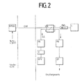
- FIG. 2 shows a block diagram of an optical transmission system with heterodyne reception, in which only one laser L and one coupler K are required.
- the components frequency shift unit FV and modulator MOD are designed as reflecting components, that is to say as reflection frequency shift unit RFV and reflection modulator RMOD, ie. that is, the input and output signals use the same gate, but in different directions.
- the components laser L, the one-way line EWL, optical attenuator D, polarization controller PR, photodiode PD and intermediate frequency filter ZF have the same function as in the embodiment shown in FIG. 1.
- the unmodulated optical carrier is divided in the coupler K.
- the optical signal emerging at the gate 4 is fed via the polarization controller PR and the optical attenuator D to the reflection frequency shifting unit RFV and its optical frequency is shifted by the amount ⁇ f.
- This optical signal is reached as local laser wave LL the coupler K again at gate 4 and exits at gate 2.
- the portion emerging at gate 1 is blocked by the one-way line EWL.
- the optical signal emerging at the gate 3 of the coupler K is transmitted from the transmission path EMF towards the transmission side, modulated there with the useful signal in the reflection modulator RMOD and passes through the transmission path EMF again in this form, but now in the opposite direction, in order to enter the gate 3 of the Coupler K to enter and to be mixed via gate 2 of the coupler K together with the frequency-shifted local laser wave LL by the photodiode PD. Further processing takes place as in the exemplary embodiment in FIG. 1.
Landscapes
- Electromagnetism (AREA)
- Engineering & Computer Science (AREA)
- Computer Networks & Wireless Communication (AREA)
- Signal Processing (AREA)
- Physics & Mathematics (AREA)
- Optical Communication System (AREA)
- Prostheses (AREA)
- Manufacture, Treatment Of Glass Fibers (AREA)
- Cable Accessories (AREA)
- Optical Record Carriers And Manufacture Thereof (AREA)
- Crystals, And After-Treatments Of Crystals (AREA)
- Organic Low-Molecular-Weight Compounds And Preparation Thereof (AREA)
- Electrochromic Elements, Electrophoresis, Or Variable Reflection Or Absorption Elements (AREA)
- Two-Way Televisions, Distribution Of Moving Picture Or The Like (AREA)
- Input Circuits Of Receivers And Coupling Of Receivers And Audio Equipment (AREA)
- Transmitters (AREA)
Abstract
Description
Die Erfindung betrifft ein Verfahren zur optischen Nachrichtenübertragung gemäß dem Oberbegriff des Hauptanspruches.The invention relates to a method for optical message transmission according to the preamble of the main claim.
Das Prinzip des Ein-Laser-Heterodynempfangs ist aus der optischen Meßtechnik bekannt.The principle of single-laser heterodyne reception is known from optical measurement technology.
In mehreren Veröffentlichungen, z. B. in "Electronics Letters" Vol. 16 (1980) S. 630-631 oder in IEEE Journ. of Quantum Electronics, Vol. 22 (1986) S. 2070-2074 ist dieses Meßprinzip beschrieben. Als Ziel wird immer die Messung der spektralen Leistungsdichte des Laserphasenrauschens angestrebt. Das bekannte Meßsystem wird immer an einem Ort, z. B. in einem Labor aufgebaut.In several publications, e.g. B. in "Electronics Letters" Vol. 16 (1980) pp. 630-631 or in IEEE Journ. of Quantum Electronics, Vol. 22 (1986) pp. 2070-2074, this measuring principle is described. The aim is always to measure the spectral power density of the laser phase noise. The known measuring system is always in one place, for. B. set up in a laboratory.
Dadurch eignet es sich nicht zu Übertragung von modulierten optischen Signalen zwischen zwei räumlich voneinander getrennten Orten.As a result, it is not suitable for the transmission of modulated optical signals between two spatially separated locations.
Die der Erfindung zugrunde liegende Aufgabe, optische Übertragungssysteme mit Heterodynempfang zur Nachrichtenübertragung zwischen zwei räumlich voneinander weit entfernten Orten bei Verwendung von nur einem Laser zu entwerfen, wird durch die im Hauptanspruch gekennzeichnete Erfindung gelöst.The object on which the invention is based, to design optical transmission systems with heterodyne reception for transmitting messages between two locations which are spatially far apart from one another when using only one laser, is achieved by the invention characterized in the main claim.
Vorteilhafte Weiterbildungen der Erfindung sind in den Unteransprüchen beschrieben.Advantageous developments of the invention are described in the subclaims.
Die mit der Erfindung erzielten Vorteile bestehen insbesondere darin, daß durch die Mischung eines starken Signals (Lokallaser) mit einem schwachen von der Übertragungsstrecke kommenden modulierten Signals die Empfängerempfindlichkeit gegenüber dem Direktempfangsprinzip erhöht wird, daß auf der Sendeseite nur passive optische Bauelemente verwendet werden, daß nur ein Laser verwendet wird und daß die Frequenzregelung des Lokallasers durch ZF-Spannungsrückführung entfällt, da eine vorhandene Laserfrequenzdrift in beiden Wegen gleichsinnig, nur um die Signallaufzeit durch die Einmodenfaser zeitlich versetzt, auftritt. Da eine solche Frequenzdrift hauptsächlich thermische Ursachen hat, ist diese bei einem gut temperaturstabilisierten Laser langsam, so daß der Laufzeitunterschied nicht störend wirkt.The advantages achieved by the invention are, in particular, that by mixing a strong signal (local laser) with a weak modulated signal coming from the transmission path, the receiver sensitivity to the direct reception principle is increased, that only passive optical components are used on the transmission side, that only a laser is used and that the frequency control of the local laser due to IF voltage feedback is omitted, since an existing laser frequency drift occurs in both directions in the same direction, only at a time delayed by the single-mode fiber. Since such a frequency drift has mainly thermal causes, it is slow in a well temperature-stabilized laser, so that the difference in transit time does not have a disturbing effect.
Weiterhin ist vorteilhaft daß eine frequenzmäßige Abstimmung verschiedener Laser nicht erforderlich ist und daß die Einstellung der Zwischenfrequenz nicht über den Laser, der sehr frequenzempfindlich auf Strom- und Temperaturänderungen reagiert, sondern mittels einer passiven Frequenzverschiebeeinheit erfolgt. Dadurch entfällt die kritische Einstellung des Laserarbeitspunktes.Furthermore, it is advantageous that frequency-matching of different lasers is not necessary and that the intermediate frequency is not set by the laser, which is very frequency-sensitive to changes in current and temperature, but by means of a passive frequency shifting unit. This eliminates the critical setting of the laser operating point.
Weiterhin sind alle systemtechnischen Variationsmöglichkeiten, wie sie die Heterodynsysteme bieten, auch hier gegeben. Insbesondere gibt es keine Einschränkungen für das Modulationsverfahren in Hinsicht auf analog oder digital. Statt eines Polarisationsreglers kann auch Polarisationsdiversityempfang vorgenommen werden. Optische Verstärker lassen sich an geeigneten Systemstellen einsetzen, auch ist optischer Frequenzmultiplexbetrieb möglich. Das erfindungsgemäße Verfahren läßt sich u. a. vorteilhaft für Breitbandübertragung im Teilnehmeranschlußbereich anwenden. Dort sind die Anschlußlängen zwischen Vermittlungsstelle und Teilnehmer kurz (maximal 10 km) und die Anzahl der zu erwartenden Anwendungsfälle ist sehr hoch. Deshalb müssen solche Systeme billig und einfach sein, was mit diesem System, verglichen mit den bekannten glasfasergebundenen Zwei-Laser-Heterodynsystemen, gewährleistet ist.Furthermore, all system-technical variation possibilities, as offered by the heterodyne systems, are also given here. In particular, there are no restrictions on the modulation method with regard to analog or digital. Instead of a polarization controller, polarization diversity reception is also possible be made. Optical amplifiers can be used at suitable system locations, and optical frequency multiplex operation is also possible. The method according to the invention can be used advantageously, inter alia, for broadband transmission in the subscriber access area. There, the connection lengths between the exchange and the subscriber are short (maximum 10 km) and the number of expected use cases is very high. Such systems must therefore be cheap and simple, which is guaranteed with this system compared to the known glass fiber-bound two-laser heterodyne systems.
Die Erfindung wird anhand der in Fig. 1 und Fig. 2 dargestellten Ausführungsbeispielen näher beschrieben.The invention is described in more detail with reference to the exemplary embodiments shown in FIGS. 1 and 2.
Es zeigen
- Fig. 1 ein Blockschaltbild eines optischen Übertragungssystems mit Heterodynempfang bei Verwendung nur eines Lasers und drei Kopplern.
- Fig. 2 ein Blockschaltbild eines optischen Übertragungssystems mit Heterodynempfang bei Verwendung nur eines Lasers und nur eines Kopplers.
- Fig. 1 is a block diagram of an optical transmission system with heterodyne reception when using only one laser and three couplers.
- Fig. 2 is a block diagram of an optical transmission system with heterodyne reception when using only one laser and only one coupler.
In Fig. 1 ist das Blockschaltbild eines optischen Übertragungssystems mit Heterodynempfang bei Verwendung nur eines Lasers L und drei Kopplern KS, KE, KP dargestellt.1 shows the block diagram of an optical transmission system with heterodyne reception when using only one laser L and three couplers KS, KE, KP.
Der Laser L emittiert einen unmodulierten optischen Träger mit einer Bandbreite < 10 MHz. Dieser Träger läuft über eine erste optische Einwegleitung EWL1, welche Laserfrequenz- und Laserphasenfluktuationen infolge reflektierter Strahlungsanteile verhindert. Der unmodulierte optische Träger wird im Tor 1 des empfangsseitig angeordneten Kopplers KE, der in Richtung Sendeseite als Verzweiger arbeitet, eingespeist und auf Tor 3 und Tor 4 aufgeteilt. Der den Koppler KE am Tor 4 verlassende Trägeranteil ist die Lokallaserwelle LL, während der am Tor 3 austretende Trägeranteil der Sendeseite über die Einmodenfaser EMF zugeführt wird. Dort findet - alternativ zur Frequenzverschiebung im empfangsseitigen Zweig am Tor 4 von Koppler KE - zunächst die optische Frequenzverschiebung um Δ f in der Frequenzverschiebeeinheit FV sowie im Modulator MOD die Modulation des Trägers mit dem Nutzsignal statt.The laser L emits an unmodulated optical carrier with a bandwidth <10 MHz. This carrier runs over a first optical one-way line EWL1, which prevents laser frequency and laser phase fluctuations due to reflected radiation components. The unmodulated optical carrier is fed into
Die sendeseitige zweite Einwegleitung EWL2 ist dann notwendig, wenn die den Modulator MOD und die Frequenzverschiebeeinheit FV in beiden Richtungen durchlaufenden Trägeranteile sich gegenseitig stören. Der am Ausgang der zweiten Einwegleitung EWL2 mit dem Nutzsignal modulierte und frequenzverschobene Träger wird über den Koppler KS auf die Einmodenfaser EMF gegeben und läuft in Richtung Empfangsseite.The second one-way line EWL2 on the transmission side is necessary if the carrier components passing through the modulator MOD and the frequency shift unit FV interfere with one another in both directions. The carrier which is modulated and frequency-shifted at the output of the second one-way line EWL2 with the useful signal is applied to the single-mode fiber EMF via the coupler KS and runs in the direction of the receiving side.
Dort wird im Koppler KE das modulierte optische Signal von Tor 3 nach Tor 2 übergekoppelt und über einen Polarisationsregler PF, in dem der Polarisationszustand des modulierten optischen Signals dem der Lokallaserwelle LL angepaßt wird, im Koppler KP mit der Lokallaserwelle LL, die in ihrer Leistung in einem optischen Dämpfungsglied D auf optimale Empfängerempfindlichkeit eingestellt werden kann, zusammengeführt.There, the modulated optical signal is coupled from
Die Mischung und Zwischenfrequenzerzeugung erfolgt, wie bei den bekannten Lösungsvorschlägen für andere Heterodynsysteme auch, in einer Photodiode PD. Ein nachfolgendes Zwischenfrequenzfilter ZF muß auf die Mittenfrequenz Δ f eingestellt sein, damit das ZF-Signal weitgehend unverzerrt der Demodulationsstufe zugeleitet wird.The mixing and intermediate frequency generation takes place, as in the known solution proposals for other heterodyne systems, in a photodiode PD. A subsequent intermediate frequency filter IF must be set to the center frequency Δ f so that the IF signal is fed to the demodulation stage largely undistorted.
Fig. 2 zeigt ein Blockschaltbild eines optischen Übertragungssystems mit Heterodynempfang, bei dem nur ein Laser L und ein Koppler K benötigt wird.FIG. 2 shows a block diagram of an optical transmission system with heterodyne reception, in which only one laser L and one coupler K are required.
Im Gegensatz zum in Fig. 1 gezeigten Ausführungsbeispiel wird in diesem Ausführungsbeispiel nur ein 4-Tor Koppler K verwendet. Die Bauteile Frequenzverschiebeeinheit FV und Modulator MOD sind als reflektierende Komponenten, also als Reflexionsfrequenzverschiebeeinheit RFV und Reflexionsmodulator RMOD ausgeführt, d. h., Eingangs- und Ausgangssignal benutzen dasselbe Tor, jedoch in verschiedenen Richtungen.In contrast to the exemplary embodiment shown in FIG. 1, only a 4-port coupler K is used in this exemplary embodiment. The components frequency shift unit FV and modulator MOD are designed as reflecting components, that is to say as reflection frequency shift unit RFV and reflection modulator RMOD, ie. that is, the input and output signals use the same gate, but in different directions.
Die Bauteile Laser L, die Einwegleitung EWL, optisches Dämpfungsglied D, Polarisationsregler PR, Photodiode PD und Zwischenfrequenzfilter ZF haben die gleiche Funktion wie im in Fig. 1 dargestellten Ausführungsbeispiel. Der unmodulierte optische Träger wird im Koppler K aufgteilt. Das am Tor 4 austretende optische Signal wird über den Polarisationsregler PR und das optische Dämpfungsglied D der Reflexionsfrequenzverschiebeeinheit RFV zugeführt und in seiner optischen Frequenz um den Betrag Δ f verschoben. Dieses optische Signal erreicht als Lokallaserwelle LL den Koppler K wieder am Tor 4 und tritt am Tor 2 aus. Der am Tor 1 austretende Anteil wird durch die Einwegleitung EWL blockiert. Das am Tor 3 des Kopplers K austretende optische Signal wird von der Übertragungsstrecke EMF in Richtung Sendeseite übertragen, dort im Reflexionsmodulator RMOD mit dem Nutzsignal moduliert und durchläuft in dieser Form die Übertragungsstrecke EMF erneut, allerdings jetzt in umgekehrter Richtung, um in das Tor 3 des Kopplers K einzutreten und über Tor 2 des Kopplers K gemeinsam mit der frequenzverschobenen Lokallaserwelle LL durch die Photodiode PD gemischt zu werden. Die weitere Verarbeitung erfolgt wie bei dem Ausführungsbeispiel in Fig. 1.The components laser L, the one-way line EWL, optical attenuator D, polarization controller PR, photodiode PD and intermediate frequency filter ZF have the same function as in the embodiment shown in FIG. 1. The unmodulated optical carrier is divided in the coupler K. The optical signal emerging at the
Claims (9)
daß einer der Anteile des unmodulierten optischen Träger um den Betrag Δf frequenzverschoben wird,
daß der erste Anteil des unmodulierten optischen Trägers die Einmodenfaser (EMF) in Richtung Sendeseite durchläuft,
daß der erste Anteil des unmodulierten optischen Trägers sendeseitig in einem Modulator (MOD) mit einem Nutzsignal moduliert wird,
daß dieses modulierte optische Signal der Einmodenfaser (EMF) wieder zugeführt wird und in umgekehrter Richtung zur Empfangsseite läuft,
daß das modulierte optische Signal über den ersten faseroptischen Koppler (KE) zusammen mit der Lokallaserwelle (LL) einer Photodiode (PD) zugeführt wird und dort in das Zwischenfrequenzband mit fZ =Δf als Mittenfrequenz umgesetzt wird.1. A method for optical communication between spatially separate transmitter and receiver according to the principle of heterodyne reception when using only one laser, characterized in that an unmodulated optical carrier of a laser (L) arranged on the receiving side is divided into two parts, a first part a first fiber-optic coupler (KE) is used to feed a transmission path (EMF) consisting of a single-mode fiber and a second portion forms the local laser wave (LL),
that one of the components of the unmodulated optical carrier is frequency shifted by the amount Δf,
that the first portion of the unmodulated optical carrier passes through the single-mode fiber (EMF) in the direction of the transmission side,
that the first portion of the unmodulated optical carrier is modulated on the transmission side in a modulator (MOD) with a useful signal,
that this modulated optical signal is fed back to the single-mode fiber (EMF) and runs in the opposite direction to the receiving side,
that the modulated optical signal is fed via the first fiber optic coupler (KE) together with the local laser wave (LL) to a photodiode (PD) and is converted there into the intermediate frequency band with fZ = Δf as the center frequency.
Priority Applications (1)
| Application Number | Priority Date | Filing Date | Title |
|---|---|---|---|
| AT88730074T ATE78642T1 (en) | 1987-04-21 | 1988-03-24 | METHOD OF OPTICAL MESSAGE TRANSMISSION WITH HETERODYNE RECEPTION. |
Applications Claiming Priority (2)
| Application Number | Priority Date | Filing Date | Title |
|---|---|---|---|
| DE3713340 | 1987-04-21 | ||
| DE19873713340 DE3713340A1 (en) | 1987-04-21 | 1987-04-21 | METHOD FOR OPTICAL MESSAGE TRANSMISSION |
Publications (3)
| Publication Number | Publication Date |
|---|---|
| EP0288418A2 true EP0288418A2 (en) | 1988-10-26 |
| EP0288418A3 EP0288418A3 (en) | 1990-06-13 |
| EP0288418B1 EP0288418B1 (en) | 1992-07-22 |
Family
ID=6325994
Family Applications (1)
| Application Number | Title | Priority Date | Filing Date |
|---|---|---|---|
| EP19880730074 Expired - Lifetime EP0288418B1 (en) | 1987-04-21 | 1988-03-24 | Optical information transmission method with heterodyne reception |
Country Status (15)
| Country | Link |
|---|---|
| US (1) | US4882771A (en) |
| EP (1) | EP0288418B1 (en) |
| JP (1) | JPS63282722A (en) |
| AT (1) | ATE78642T1 (en) |
| AU (1) | AU597816B2 (en) |
| CA (1) | CA1282832C (en) |
| DE (2) | DE3713340A1 (en) |
| DK (1) | DK168932B1 (en) |
| ES (1) | ES2034356T3 (en) |
| GR (1) | GR3005367T3 (en) |
| IE (1) | IE61991B1 (en) |
| NO (1) | NO171819C (en) |
| PT (1) | PT87271B (en) |
| TR (1) | TR26000A (en) |
| ZA (1) | ZA882756B (en) |
Cited By (1)
| Publication number | Priority date | Publication date | Assignee | Title |
|---|---|---|---|---|
| EP0496298A3 (en) * | 1991-01-23 | 1993-03-17 | Gte Laboratories Incorporated | Quadrature optical phase modulators for lightwave systems |
Families Citing this family (7)
| Publication number | Priority date | Publication date | Assignee | Title |
|---|---|---|---|---|
| DE3827228A1 (en) * | 1988-08-11 | 1990-02-15 | Standard Elektrik Lorenz Ag | TRANSMITTER / RECEIVER FOR A BIDIRECTIONAL COHERENT-OPTICAL TRANSMISSION SYSTEM |
| DE3900095C2 (en) * | 1989-01-04 | 1998-08-20 | Kommunikations Elektronik | Process for the transmission of optical signals via optical fibers according to the superimposition principle |
| US4972514A (en) * | 1989-02-08 | 1990-11-20 | At&T Bell Laboratories | Full duplex lightwave communication system |
| EP0386736B1 (en) * | 1989-03-09 | 1995-06-07 | Canon Kabushiki Kaisha | Optical communications system |
| DE4019224A1 (en) * | 1990-06-15 | 1991-12-19 | Standard Elektrik Lorenz Ag | RADIO NEWS TRANSMISSION SYSTEM, IN PARTICULAR CELLULAR MOBILE RADIO SYSTEM |
| US6868233B2 (en) * | 2000-12-14 | 2005-03-15 | Alcatel Usa Sourcing, L.P. | Wavelength agile optical transponder for bi-directional, single fiber WDM system testing |
| US9203513B2 (en) * | 2008-05-15 | 2015-12-01 | Teledyne Scientific & Imaging, Llc | SNR enhancement in modulating retroreflector optical communication links |
Family Cites Families (5)
| Publication number | Priority date | Publication date | Assignee | Title |
|---|---|---|---|---|
| US3433960A (en) * | 1966-10-31 | 1969-03-18 | Nasa | Retrodirective optical system |
| AU525304B2 (en) * | 1978-06-13 | 1982-10-28 | Amalgamated Wireless (Australasia) Limited | Optical fibre communication links |
| FR2513049A1 (en) * | 1981-09-15 | 1983-03-18 | Thomson Csf | Fibre=optic communication system for telephone network - uses duplexer at main station with input to transmission channel and output to receiving channel |
| US4777661A (en) * | 1986-09-22 | 1988-10-11 | Simmonds Precision Products, Inc. | Apparatus and method for self-referencing and multiplexing intensity modulating fiber optic sensors |
| DE3883499D1 (en) * | 1987-12-07 | 1993-09-30 | Siemens Ag | Optical superimposed receiver for digital signals. |
-
1987
- 1987-04-21 DE DE19873713340 patent/DE3713340A1/en not_active Withdrawn
-
1988
- 1988-03-24 AT AT88730074T patent/ATE78642T1/en not_active IP Right Cessation
- 1988-03-24 ES ES198888730074T patent/ES2034356T3/en not_active Expired - Lifetime
- 1988-03-24 EP EP19880730074 patent/EP0288418B1/en not_active Expired - Lifetime
- 1988-03-24 DE DE8888730074T patent/DE3872921D1/en not_active Expired - Lifetime
- 1988-03-29 IE IE94988A patent/IE61991B1/en not_active IP Right Cessation
- 1988-04-07 CA CA000563534A patent/CA1282832C/en not_active Expired - Lifetime
- 1988-04-13 TR TR88/0277A patent/TR26000A/en unknown
- 1988-04-19 DK DK213188A patent/DK168932B1/en not_active IP Right Cessation
- 1988-04-19 JP JP63094699A patent/JPS63282722A/en active Pending
- 1988-04-19 PT PT87271A patent/PT87271B/en not_active IP Right Cessation
- 1988-04-20 AU AU14793/88A patent/AU597816B2/en not_active Ceased
- 1988-04-20 NO NO881702A patent/NO171819C/en unknown
- 1988-04-20 ZA ZA882756A patent/ZA882756B/en unknown
- 1988-04-21 US US07/184,290 patent/US4882771A/en not_active Expired - Fee Related
-
1992
- 1992-08-06 GR GR920401700T patent/GR3005367T3/el unknown
Non-Patent Citations (3)
| Title |
|---|
| ELECTRONIC DESIGN, Band 15, Nr. 12, Juni 1967, Seite 104, Rochelle Park, NJ, US; "AM receiver uses laser LO" * |
| ELECTRONICS LETTERS, Band 22, Nr. 10, Mai 1986, Seiten 517-518, Stevenage, Herts, GB; P.J. DUTHIE: "Bidirectional fibre-optic link using reflective modulation" * |
| ELECTRONICS LETTERS, Band 22, Nr. 9, April 1986, Seiten 479-481, Stevenage, Herts, GB; J.K. WHEELER et al.: "Two-way transmission using electro-optical modulator" * |
Cited By (1)
| Publication number | Priority date | Publication date | Assignee | Title |
|---|---|---|---|---|
| EP0496298A3 (en) * | 1991-01-23 | 1993-03-17 | Gte Laboratories Incorporated | Quadrature optical phase modulators for lightwave systems |
Also Published As
| Publication number | Publication date |
|---|---|
| EP0288418B1 (en) | 1992-07-22 |
| DE3713340A1 (en) | 1988-11-10 |
| NO171819C (en) | 1993-05-05 |
| EP0288418A3 (en) | 1990-06-13 |
| ZA882756B (en) | 1988-10-18 |
| ES2034356T3 (en) | 1993-04-01 |
| AU1479388A (en) | 1988-10-27 |
| TR26000A (en) | 1993-10-08 |
| DK168932B1 (en) | 1994-07-11 |
| CA1282832C (en) | 1991-04-09 |
| NO881702L (en) | 1988-10-24 |
| GR3005367T3 (en) | 1993-05-24 |
| US4882771A (en) | 1989-11-21 |
| DK213188D0 (en) | 1988-04-19 |
| IE61991B1 (en) | 1994-12-14 |
| JPS63282722A (en) | 1988-11-18 |
| IE880949L (en) | 1988-10-21 |
| ATE78642T1 (en) | 1992-08-15 |
| NO171819B (en) | 1993-01-25 |
| PT87271B (en) | 1993-09-30 |
| AU597816B2 (en) | 1990-06-07 |
| DE3872921D1 (en) | 1992-08-27 |
| DK213188A (en) | 1988-10-22 |
| NO881702D0 (en) | 1988-04-20 |
| PT87271A (en) | 1989-05-12 |
Similar Documents
| Publication | Publication Date | Title |
|---|---|---|
| EP0354567B1 (en) | Sending and receiving part for a bidirectional coherent optical communication system | |
| DE69833913T2 (en) | Suppression of coherent Rayleigh noise in bidirectional transmission systems | |
| DE69013662T2 (en) | Narrow band laser source. | |
| DE69127568T2 (en) | Telemetry for optical fiber repeaters | |
| DE3020454C2 (en) | Optical device for transmitting light rays | |
| DE3232430C2 (en) | Optical communication system | |
| EP0233617B1 (en) | Optical send and receive module | |
| DE3782556T2 (en) | LIGHT TRANSMISSION SYSTEM. | |
| DE69232475T2 (en) | Optical transmission system | |
| DE4415176A1 (en) | Device and method for dispersion compensation in a fiber optic transmission system | |
| DE69127215T2 (en) | Optical transmission method and optical transmission system | |
| DE69632733T2 (en) | DISPERSION COMPENSATION | |
| DE19722370A1 (en) | Receiver for an optical communication system and method for its operation | |
| DE2333968A1 (en) | Fibre network for data transmission - has optical fibres transmitting by optoelectronic means between any number of subscribers | |
| DE3871604T2 (en) | TRANSMITTER AND TRANSMITTER RECEIVER FOR A COHERENT OPTICAL SYSTEM. | |
| EP0349766A2 (en) | Optical information transmission system, especially in the subscriber connection field | |
| EP0288418B1 (en) | Optical information transmission method with heterodyne reception | |
| DE69720450T2 (en) | Optical dispersion compensation | |
| EP0485813A2 (en) | Optical telecommunications system with optic fiber amplifier | |
| EP0675351A2 (en) | Procedure for determining the wavelength in an optical fibre corresponding to zero dispersion | |
| DE69610431T2 (en) | METHOD AND DEVICE FOR DISTANCE MEASUREMENT IN A TDMA SYSTEM, A PASSIVE OPTICAL NETWORK | |
| WO2009109365A1 (en) | Dispersion measurement of optical fibres during operation | |
| DE4314406C2 (en) | Group antenna with optical beam shaping network | |
| EP0898390B1 (en) | Method and apparatus for generating an optical output signal | |
| EP0658015A1 (en) | Apparatus for transmitting an intensity- and phase-modulated light beam |
Legal Events
| Date | Code | Title | Description |
|---|---|---|---|
| PUAI | Public reference made under article 153(3) epc to a published international application that has entered the european phase |
Free format text: ORIGINAL CODE: 0009012 |
|
| AK | Designated contracting states |
Kind code of ref document: A2 Designated state(s): AT BE CH DE ES FR GB GR IT LI LU NL SE |
|
| PUAL | Search report despatched |
Free format text: ORIGINAL CODE: 0009013 |
|
| RAP1 | Party data changed (applicant data changed or rights of an application transferred) |
Owner name: N.V. PHILIPS' GLOEILAMPENFABRIEKEN Owner name: SIEMENS AKTIENGESELLSCHAFT Owner name: PHILIPS PATENTVERWALTUNG GMBH Owner name: KABELMETAL ELECTRO GMBH Owner name: STANDARD ELEKTRIK LORENZ AKTIENGESELLSCHAFT Owner name: KRONE AKTIENGESELLSCHAFT |
|
| AK | Designated contracting states |
Kind code of ref document: A3 Designated state(s): AT BE CH DE ES FR GB GR IT LI LU NL SE |
|
| 17P | Request for examination filed |
Effective date: 19900906 |
|
| 17Q | First examination report despatched |
Effective date: 19910328 |
|
| GRAA | (expected) grant |
Free format text: ORIGINAL CODE: 0009210 |
|
| AK | Designated contracting states |
Kind code of ref document: B1 Designated state(s): AT BE CH DE ES FR GB GR IT LI LU NL SE |
|
| REF | Corresponds to: |
Ref document number: 78642 Country of ref document: AT Date of ref document: 19920815 Kind code of ref document: T |
|
| ITF | It: translation for a ep patent filed | ||
| GBT | Gb: translation of ep patent filed (gb section 77(6)(a)/1977) | ||
| REF | Corresponds to: |
Ref document number: 3872921 Country of ref document: DE Date of ref document: 19920827 |
|
| ET | Fr: translation filed | ||
| RAP4 | Party data changed (patent owner data changed or rights of a patent transferred) |
Owner name: N.V. PHILIPS' GLOEILAMPENFABRIEKEN Owner name: SIEMENS AKTIENGESELLSCHAFT Owner name: PHILIPS PATENTVERWALTUNG GMBH Owner name: KABELMETAL ELECTRO GMBH Owner name: ALCATEL SEL AKTIENGESELLSCHAFT Owner name: KRONE AKTIENGESELLSCHAFT |
|
| REG | Reference to a national code |
Ref country code: GR Ref legal event code: FG4A Free format text: 3005367 |
|
| REG | Reference to a national code |
Ref country code: ES Ref legal event code: FG2A Ref document number: 2034356 Country of ref document: ES Kind code of ref document: T3 |
|
| PLBE | No opposition filed within time limit |
Free format text: ORIGINAL CODE: 0009261 |
|
| STAA | Information on the status of an ep patent application or granted ep patent |
Free format text: STATUS: NO OPPOSITION FILED WITHIN TIME LIMIT |
|
| 26N | No opposition filed | ||
| EPTA | Lu: last paid annual fee | ||
| EAL | Se: european patent in force in sweden |
Ref document number: 88730074.7 |
|
| ITPR | It: changes in ownership of a european patent |
Owner name: CAMBIO RAGIONE SOCIALE;PHILIPS ELECTRONICS N.V. |
|
| PGFP | Annual fee paid to national office [announced via postgrant information from national office to epo] |
Ref country code: LU Payment date: 19960301 Year of fee payment: 9 |
|
| PGFP | Annual fee paid to national office [announced via postgrant information from national office to epo] |
Ref country code: FR Payment date: 19960314 Year of fee payment: 9 |
|
| PGFP | Annual fee paid to national office [announced via postgrant information from national office to epo] |
Ref country code: GB Payment date: 19960315 Year of fee payment: 9 |
|
| PGFP | Annual fee paid to national office [announced via postgrant information from national office to epo] |
Ref country code: BE Payment date: 19960321 Year of fee payment: 9 |
|
| PGFP | Annual fee paid to national office [announced via postgrant information from national office to epo] |
Ref country code: SE Payment date: 19960322 Year of fee payment: 9 Ref country code: AT Payment date: 19960322 Year of fee payment: 9 |
|
| PGFP | Annual fee paid to national office [announced via postgrant information from national office to epo] |
Ref country code: CH Payment date: 19960327 Year of fee payment: 9 |
|
| PGFP | Annual fee paid to national office [announced via postgrant information from national office to epo] |
Ref country code: ES Payment date: 19960328 Year of fee payment: 9 |
|
| PGFP | Annual fee paid to national office [announced via postgrant information from national office to epo] |
Ref country code: GR Payment date: 19960329 Year of fee payment: 9 |
|
| PGFP | Annual fee paid to national office [announced via postgrant information from national office to epo] |
Ref country code: NL Payment date: 19960331 Year of fee payment: 9 |
|
| PG25 | Lapsed in a contracting state [announced via postgrant information from national office to epo] |
Ref country code: LU Free format text: LAPSE BECAUSE OF NON-PAYMENT OF DUE FEES Effective date: 19970324 Ref country code: GB Effective date: 19970324 Ref country code: AT Effective date: 19970324 |
|
| PG25 | Lapsed in a contracting state [announced via postgrant information from national office to epo] |
Ref country code: SE Effective date: 19970325 Ref country code: ES Free format text: LAPSE BECAUSE OF NON-PAYMENT OF DUE FEES Effective date: 19970325 |
|
| PG25 | Lapsed in a contracting state [announced via postgrant information from national office to epo] |
Ref country code: LI Effective date: 19970331 Ref country code: CH Effective date: 19970331 Ref country code: BE Effective date: 19970331 |
|
| BERE | Be: lapsed |
Owner name: KRONE A.G. Effective date: 19970331 |
|
| PG25 | Lapsed in a contracting state [announced via postgrant information from national office to epo] |
Ref country code: GR Free format text: THE PATENT HAS BEEN ANNULLED BY A DECISION OF A NATIONAL AUTHORITY Effective date: 19970930 |
|
| PG25 | Lapsed in a contracting state [announced via postgrant information from national office to epo] |
Ref country code: NL Effective date: 19971001 |
|
| REG | Reference to a national code |
Ref country code: GR Ref legal event code: MM2A Free format text: 3005367 |
|
| GBPC | Gb: european patent ceased through non-payment of renewal fee |
Effective date: 19970324 |
|
| REG | Reference to a national code |
Ref country code: CH Ref legal event code: PL |
|
| PG25 | Lapsed in a contracting state [announced via postgrant information from national office to epo] |
Ref country code: FR Free format text: LAPSE BECAUSE OF NON-PAYMENT OF DUE FEES Effective date: 19971128 |
|
| NLV4 | Nl: lapsed or anulled due to non-payment of the annual fee |
Effective date: 19971001 |
|
| EUG | Se: european patent has lapsed |
Ref document number: 88730074.7 |
|
| REG | Reference to a national code |
Ref country code: FR Ref legal event code: ST |
|
| PGFP | Annual fee paid to national office [announced via postgrant information from national office to epo] |
Ref country code: DE Payment date: 19980603 Year of fee payment: 11 |
|
| REG | Reference to a national code |
Ref country code: ES Ref legal event code: FD2A Effective date: 19990301 |
|
| PG25 | Lapsed in a contracting state [announced via postgrant information from national office to epo] |
Ref country code: DE Free format text: LAPSE BECAUSE OF NON-PAYMENT OF DUE FEES Effective date: 20000101 |
|
| PG25 | Lapsed in a contracting state [announced via postgrant information from national office to epo] |
Ref country code: IT Free format text: LAPSE BECAUSE OF NON-PAYMENT OF DUE FEES Effective date: 20050324 |