EP0288600B1 - Maschine zum Formen von Rundpressballen - Google Patents
Maschine zum Formen von Rundpressballen Download PDFInfo
- Publication number
- EP0288600B1 EP0288600B1 EP87112702A EP87112702A EP0288600B1 EP 0288600 B1 EP0288600 B1 EP 0288600B1 EP 87112702 A EP87112702 A EP 87112702A EP 87112702 A EP87112702 A EP 87112702A EP 0288600 B1 EP0288600 B1 EP 0288600B1
- Authority
- EP
- European Patent Office
- Prior art keywords
- gate
- support
- bale
- machine
- discharge position
- Prior art date
- Legal status (The legal status is an assumption and is not a legal conclusion. Google has not performed a legal analysis and makes no representation as to the accuracy of the status listed.)
- Expired
Links
Images

Classifications
-
- A—HUMAN NECESSITIES
- A01—AGRICULTURE; FORESTRY; ANIMAL HUSBANDRY; HUNTING; TRAPPING; FISHING
- A01F—PROCESSING OF HARVESTED PRODUCE; HAY OR STRAW PRESSES; DEVICES FOR STORING AGRICULTURAL OR HORTICULTURAL PRODUCE
- A01F15/00—Baling presses for straw, hay or the like
- A01F15/08—Details
- A01F15/0875—Discharge devices
- A01F15/0883—Discharge devices for round balers
Definitions
- This invention relates to a baling machine for forming cylindrical bales of crop having a gate which can be raised to open it to allow a completed bale to be discharged through the opening and a support for the completed bale which is swingable on opening of the gate between a non-discharge position and a discharge position at which it forms a ramp down which the bale can roll to the ground.
- Machines towed by a tractor, for forming large cylindrical bales of hay (so called "round balers") are well known. As the machine advances, the crop is removed from a windrow by a pick-up mechanism and delivered rearwardly to a baling chamber where it is rolled into a bale.
- baling machines There are basically two forms of such machines, namely those with a fixed volume baling chamber defined by driven fixed-position rolls and those with a baling chamber defined by runs of driven belts which move outwardly to enlarge the chamber to accommodate the bale as it grows in size.
- the hay is caused by the driven movement of the rolls or belts to roll round upon itself into a core and the core rotates about its horizontal axis and finally a completed bale is formed, the chamber being fed throughout with hay.
- the completed bale is tied with twine to maintain its shape and is discharged by rolling through a gate formed by a rear portion of the machine.
- the gate is swingable about a horizontal pivot axis located at the top of the baler so that the gate moves rearwardly and upwardly from a closed position in which it is approximately vertical to a fully open position at an angle of about 60° to the vertical at which the completed bale can pass freely under it.
- GB-A-2 138 354 it has been proposed to provide a support in the form of a grid which is triggered to move from a horizontal position against a spring loading to a downwardly inclined position immediately opening of the gate has started in which position it supports the bale and allows the bale to run down it as a ramp to the ground. After discharge, an automatic signal indicates to the driver whether the bale is clear of the gate swing area.
- the grid extends far beyond the rear of the machine when the gate is closed so that the bale would probably be deposited sufficiently clear of the gate generally to enable closure without fouling. However, this adds significantly to the overall length of the machine.
- the present invention reduces or eliminates the problem of insufficient rolling of the bale from the gate, without the necessity for increasing the length of the machine, by a very simple design.
- the support is biased toward the discharge position, and is maintained in the non-discharge position against the bias by the gate.
- the gate preferably has an abutment which, when the gate is closed, contacts the support so as to prevent the support swinging under its bias away from the non- discharge position, and, when the gate opens, moves out of contact with the support so as to release it.
- the bias can be provided by a compression spring or springs.
- the baler includes a main frame 10 mounted on a pair of wheels of which only the left hand wheel 12 is shown.
- the main frame has an upright fore- and-aft extending wall 14 on either side connected by transverse beams (not shown).
- a draft tongue 16 is connected to a transverse beam at the front of the frame 10 and extends forwardly for attaching the baler to a tractor which draws the machine.
- a plurality of lateral rolls e.g. roll 18, extends over its width carrying belts 20 which define an expanding bale-forming chamber the ends of which are provided by the side walls 14 and a rear gate 22 and which has an inlet 24 for crop received from a pick-up 26 beneath it.
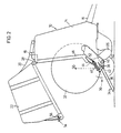
- the gate 22 is swingable upwardly and rearwardly from its closed position in Fig. 1 about a pivot axis 28 at the top of the machine to its open position in Fig. 2.
- a support arrangement 30 is provided for a completed bale 32 as shown in Fig. 2.
- This arrangement includes a normally horizontal support 34 below the rearward portion of the bale-forming chamber, when at its maximum size for the completed bale 32, and located just above wheel 12 axle level.
- the support 34 has two longitudinal side beams 36, only the right hand one being shown, and extends rearwardly but does not protrude beyond the back of the gate 22 so the support 34 is contained well within the confines of the rest of the machine.
- the support 34 is pivotally mounted at a position towards its forward end by way of a horizontal shaft 38 with which it is rigid. Its forward end abuts, when in the horizontal position of Fig. 1, a stop bar 40 below it. It is not necessary for the support 34 to be exactly horizontal in the Fig. 1 position and, if desired, it may have some rearwardly directed downward slope of, for example, 10°.
- a lever 42 rigid with the horizontal shaft 38, is disposed outwardly of the side beam 36 and extends upwardly and rearwardly.
- a bracket 44 is attached to an upright beam 46, in front of the gate 22, of the side wall 14, and an adjustable compression spring 48 is mounted on a rod 50 pivotally connected to the upper end of the lever 42 and received through the bracket 44 so that it strongly urges the support 34 downwardly in an anti- clockwise direction.
- An adjustment nut 52 is engaged on the upper end of the rod 50.
- an abutment bar 54 Opposed to this spring bias is an abutment bar 54 which extends over the width of the machine in contact with the forward end of the support 34 and is rigid with a leg 56 (on both sides of the machine) bolted to a forward lower portion of the gate 22.
- the gate 22 In operation, after the completed bale 32 has been formed and tied with twine the gate 22 is opened.
- the centre 58 of the bale initially overlies a point on the support 34 just to the rear of the horizontal shaft 38.
- the abutment bar 54 On opening of the gate 22, the abutment bar 54 will, of course, move rearwardly and upwardly so that it rapidly moves out of contact with the support 34 enabling the latter to be thrust downwardly immediately by the loading of the springs 48 on either side of the machine.
- the present baler is designed so that energy from the bale 32 is not used in overcoming the bias 48 of the support 34, and therefore the bale, when it reaches the ground, tends to roll further away from the support 34 and consequently is less likely to be in a position where it will obstruct the gate 22 on closure. It is the closing of the gate 22 which imparts energy to the arrangement 30 for future unloading movement of the support 34 in that, as the gate 22 returns to its closed position, the abutment bar 54 contacts the forward end portion of the support 34 swinging it clockwise to restore it to the horizontal non-discharge position and to compress the springs 48.
Landscapes
- Life Sciences & Earth Sciences (AREA)
- Environmental Sciences (AREA)
- Harvesting Machines For Specific Crops (AREA)
- Storage Of Harvested Produce (AREA)
Claims (5)
- Ballenformmaschine zum Bilden von zylindrischen Ballen aus Erntegut mit einem Tor (22), das zum Öffnen angehoben werden kann, um das Entladen eines fertiggestellten Ballens (32) durch die Öffnung zu erlauben, und mit einer Stützeinrichtung (34) für den fertiggestellten Ballen (32), die beim Öffnen des Tores (22) zwischen einer Nicht-Entladestellung und einer Entladestellung schwenkbar ist, in der sie eine Rampe bildet, auf der der Ballen (32) auf den Boden herabrollen kann, dadurch gekennzeich net, daß die Stützeinrichtung (34) in Richtung auf die Entladestellung vorgespannt und in der Nicht-Entladestellung entgegen der Vorspannung (48) durch das Tor (22) gehalten ist.
- Ballenformmaschine nach Anspruch 1, dadurch gekennzeichnet,daß das Tor (22) einen Anschlag (54) aufweist, der, wenn das Tor (22) geschlossen ist, mit der Stützeinrichtung kontakt hat, um zu verhindern, daß die Stützeinrichtung (34) unter ihrer Vorspannung (48) aus der Nicht-Entlade-stellung wegschwenkt, und, wenn das Tor (22) öffnet, sich außer kontakt mit der Stützeinrichtung (34) bewegt, um diese freizugeben.
- Ballenformmaschine nach Anspruch 1 oder 2, dadurch gekennzeich net,daß die Stützeinrichtung (34) durch eine Druckfeder oder Federn (48) vorgespannt ist.
- Ballenformmaschine nach Anspruch 3, dadurch gekennzeichnet,daß die Feder oder Federn (48) einstellbar sind.
- Ballenformmaschine nach Anspruch 3 oder 4, dadurch gekennzeich net, daß die Stützeinrichtung (34) starr an einer horizontalen Schwenkwelle (38) angebracht ist, die Welle (38) starr mit einem Hebel (42) verbunden ist und der Hebel (42) durch eine genannte Druckfeder (48) vorgespannt ist.
Applications Claiming Priority (2)
| Application Number | Priority Date | Filing Date | Title |
|---|---|---|---|
| GB8709927A GB2203986B (en) | 1987-04-27 | 1987-04-27 | Machine for forming cylindrical bales of crop |
| GB8709927 | 1987-04-27 |
Publications (2)
| Publication Number | Publication Date |
|---|---|
| EP0288600A1 EP0288600A1 (de) | 1988-11-02 |
| EP0288600B1 true EP0288600B1 (de) | 1991-03-06 |
Family
ID=10616423
Family Applications (1)
| Application Number | Title | Priority Date | Filing Date |
|---|---|---|---|
| EP87112702A Expired EP0288600B1 (de) | 1987-04-27 | 1987-09-01 | Maschine zum Formen von Rundpressballen |
Country Status (6)
| Country | Link |
|---|---|
| US (1) | US4821637A (de) |
| EP (1) | EP0288600B1 (de) |
| CA (1) | CA1318179C (de) |
| DE (1) | DE3768496D1 (de) |
| ES (1) | ES2021313B3 (de) |
| GB (1) | GB2203986B (de) |
Families Citing this family (19)
| Publication number | Priority date | Publication date | Assignee | Title |
|---|---|---|---|---|
| US6421996B1 (en) * | 2000-07-12 | 2002-07-23 | Deere & Company | Harvester with bale forming chamber having a transport mode |
| EP1266563B1 (de) * | 2001-06-11 | 2008-01-23 | Welger Maschinenfabrik GmbH | Rundballenpresse für landwirtschaftliche Halmgüter |
| EP1266562A1 (de) * | 2001-06-11 | 2002-12-18 | Lely Enterprises AG | Rundballenpresse für landwirtschaftliche Halmgüter |
| US6892632B1 (en) * | 2001-08-10 | 2005-05-17 | Gehl Company | Jointed bale kicker for a round baler |
| US6807901B2 (en) * | 2002-08-05 | 2004-10-26 | Vermeer Manufacturing Company | Two-stage spring loaded bale ramp |
| DE10312074A1 (de) * | 2003-03-18 | 2004-10-14 | Usines Claas France S.A. | Verfahren und Einrichtung zum Ver- und Entriegeln einer Ballenrampe |
| US7047876B2 (en) * | 2004-02-28 | 2006-05-23 | Cnh America Llc | Torsion bar activated round baler kicker |
| US20050257513A1 (en) * | 2004-04-01 | 2005-11-24 | Smith Kevin M | Hydraulic bale ramp |
| US20050217233A1 (en) * | 2004-04-01 | 2005-10-06 | Smith Kevin M | Hydraulic bale ramp |
| US7197979B2 (en) * | 2005-06-10 | 2007-04-03 | Deere & Company | Controlled bale ejection mechanism |
| DE102006038299A1 (de) * | 2006-08-16 | 2008-02-28 | Deere & Company, Moline | Rundballenpresse |
| US7805914B2 (en) * | 2008-03-10 | 2010-10-05 | Cnh America Llc | Hydraulic bale kicker with optional weighing device |
| US9958301B2 (en) | 2014-07-11 | 2018-05-01 | Clemson University | Impact mass flow sensor for monitoring peanut harvest yields |
| DE102015210999A1 (de) | 2015-06-16 | 2016-12-22 | Deere & Company | Abladerampe für eine Rundballenpresse |
| US10188025B2 (en) | 2015-07-14 | 2019-01-29 | Clemson University Research Foundation | Yield monitor for windrow-collected materials |
| US9968027B2 (en) | 2015-07-14 | 2018-05-15 | Clemson University | Automated control systems and methods for underground crop harvesters |
| DE102018208821A1 (de) | 2018-06-05 | 2019-12-05 | Deere & Company | Entladevorrichtung, Rundballenpresse und Entladeverfahren |
| US11547056B2 (en) * | 2020-03-11 | 2023-01-10 | Cnh Industrial America Llc | Frame assembly for an agricultural round baler |
| US11825775B2 (en) * | 2020-07-20 | 2023-11-28 | Deere & Company | Round baler with bale holder in gate |
Family Cites Families (6)
| Publication number | Priority date | Publication date | Assignee | Title |
|---|---|---|---|---|
| US4406221A (en) * | 1982-02-12 | 1983-09-27 | Sperry Corporation | Bale retainer for roll baling machine |
| DE3314314C2 (de) * | 1983-04-20 | 1994-10-27 | Claas Ohg | Rollballenpresse für landwirtschaftliche Halmgüter mit zweiteiligem Preßraumgehäuse |
| US4470247A (en) * | 1983-05-25 | 1984-09-11 | Sperry Corporation | Round bale forming machine |
| DE3419535A1 (de) * | 1984-05-25 | 1985-11-28 | Maschinenfabriken Bernard Krone Gmbh, 4441 Spelle | Maschine zum aufnehmen und pressen von rollenfoermigen ballen |
| FR2583608B1 (fr) * | 1985-06-19 | 1987-09-18 | Hesston | Dispositif pour l'ejection de balles de fourrage sur une presse a balles rondes. |
| GB2196294B (en) * | 1986-10-20 | 1991-01-23 | Deere & Co | Machine for forming cylindrical bales of crop |
-
1987
- 1987-04-27 GB GB8709927A patent/GB2203986B/en not_active Expired - Lifetime
- 1987-09-01 ES ES87112702T patent/ES2021313B3/es not_active Expired - Lifetime
- 1987-09-01 EP EP87112702A patent/EP0288600B1/de not_active Expired
- 1987-09-01 DE DE8787112702T patent/DE3768496D1/de not_active Expired - Lifetime
-
1988
- 1988-04-07 CA CA000563539A patent/CA1318179C/en not_active Expired - Fee Related
- 1988-04-25 US US07/185,652 patent/US4821637A/en not_active Expired - Lifetime
Also Published As
| Publication number | Publication date |
|---|---|
| GB2203986B (en) | 1990-12-19 |
| GB8709927D0 (en) | 1987-06-03 |
| US4821637A (en) | 1989-04-18 |
| CA1318179C (en) | 1993-05-25 |
| GB2203986A (en) | 1988-11-02 |
| DE3768496D1 (de) | 1991-04-11 |
| ES2021313B3 (es) | 1991-11-01 |
| EP0288600A1 (de) | 1988-11-02 |
Similar Documents
| Publication | Publication Date | Title |
|---|---|---|
| US4821637A (en) | Support assembly attached to a large round baler for forming a bale discharge ramp | |
| CA1213464A (en) | Cylindrical baler with bale discharge ejector | |
| US4798044A (en) | Machine for forming cylindrical bales of crop | |
| US5855109A (en) | Apparatus for making round bales | |
| US6421996B1 (en) | Harvester with bale forming chamber having a transport mode | |
| EP0265583B1 (de) | Rundballenpresse | |
| GB2138354A (en) | Agricultural rolled bale baler with a two-part bale chamber housing | |
| US6134870A (en) | Bale discharge means for a rectangular baler | |
| US7197979B2 (en) | Controlled bale ejection mechanism | |
| EP0974260B1 (de) | Bewegbare Ballenablagevorrichtung für eine Ballenpresse | |
| US5598690A (en) | Tailgate latching apparatus for a round baler | |
| US4135352A (en) | Semicontinuous large round baling machine | |
| EP0401581B1 (de) | Maschine zum Formen zylindrischer Ballen aus Futterpflanzen | |
| EP0235787B1 (de) | Maschine zur Bildung von Rundballen | |
| US4759278A (en) | Machine for forming cylindrical bales of crop | |
| US4813348A (en) | Machine for forming cylindrical bales of crop | |
| US4446684A (en) | Cylindrical baler with flare sheets on crop pickup | |
| US7047876B2 (en) | Torsion bar activated round baler kicker | |
| GB2195577A (en) | Machine for forming cylindrical bales of crop |
Legal Events
| Date | Code | Title | Description |
|---|---|---|---|
| PUAI | Public reference made under article 153(3) epc to a published international application that has entered the european phase |
Free format text: ORIGINAL CODE: 0009012 |
|
| AK | Designated contracting states |
Kind code of ref document: A1 Designated state(s): DE ES FR GB IT NL |
|
| 17P | Request for examination filed |
Effective date: 19881216 |
|
| 17Q | First examination report despatched |
Effective date: 19900816 |
|
| ITF | It: translation for a ep patent filed | ||
| GRAA | (expected) grant |
Free format text: ORIGINAL CODE: 0009210 |
|
| AK | Designated contracting states |
Kind code of ref document: B1 Designated state(s): DE ES FR GB IT NL |
|
| REF | Corresponds to: |
Ref document number: 3768496 Country of ref document: DE Date of ref document: 19910411 |
|
| ET | Fr: translation filed | ||
| PLBE | No opposition filed within time limit |
Free format text: ORIGINAL CODE: 0009261 |
|
| 26N | No opposition filed | ||
| PGFP | Annual fee paid to national office [announced via postgrant information from national office to epo] |
Ref country code: ES Payment date: 19930913 Year of fee payment: 7 |
|
| PGFP | Annual fee paid to national office [announced via postgrant information from national office to epo] |
Ref country code: GB Payment date: 19940726 Year of fee payment: 8 |
|
| PG25 | Lapsed in a contracting state [announced via postgrant information from national office to epo] |
Ref country code: ES Free format text: LAPSE BECAUSE OF EXPIRATION OF PROTECTION Effective date: 19940902 |
|
| PG25 | Lapsed in a contracting state [announced via postgrant information from national office to epo] |
Ref country code: GB Effective date: 19950901 |
|
| GBPC | Gb: european patent ceased through non-payment of renewal fee |
Effective date: 19950901 |
|
| REG | Reference to a national code |
Ref country code: ES Ref legal event code: FD2A Effective date: 19990601 |
|
| PGFP | Annual fee paid to national office [announced via postgrant information from national office to epo] |
Ref country code: NL Payment date: 20050816 Year of fee payment: 19 |
|
| PGFP | Annual fee paid to national office [announced via postgrant information from national office to epo] |
Ref country code: FR Payment date: 20050919 Year of fee payment: 19 |
|
| PGFP | Annual fee paid to national office [announced via postgrant information from national office to epo] |
Ref country code: DE Payment date: 20050930 Year of fee payment: 19 |
|
| PGFP | Annual fee paid to national office [announced via postgrant information from national office to epo] |
Ref country code: IT Payment date: 20060930 Year of fee payment: 20 |
|
| PG25 | Lapsed in a contracting state [announced via postgrant information from national office to epo] |
Ref country code: NL Free format text: LAPSE BECAUSE OF NON-PAYMENT OF DUE FEES Effective date: 20070401 |
|
| PG25 | Lapsed in a contracting state [announced via postgrant information from national office to epo] |
Ref country code: DE Free format text: LAPSE BECAUSE OF NON-PAYMENT OF DUE FEES Effective date: 20070403 |
|
| NLV4 | Nl: lapsed or anulled due to non-payment of the annual fee |
Effective date: 20070401 |
|
| REG | Reference to a national code |
Ref country code: FR Ref legal event code: ST Effective date: 20070531 |
|
| PG25 | Lapsed in a contracting state [announced via postgrant information from national office to epo] |
Ref country code: FR Free format text: LAPSE BECAUSE OF NON-PAYMENT OF DUE FEES Effective date: 20061002 |