EP0288623A1 - Elektrisch betätigbarer Vorhang - Google Patents
Elektrisch betätigbarer Vorhang Download PDFInfo
- Publication number
- EP0288623A1 EP0288623A1 EP87303767A EP87303767A EP0288623A1 EP 0288623 A1 EP0288623 A1 EP 0288623A1 EP 87303767 A EP87303767 A EP 87303767A EP 87303767 A EP87303767 A EP 87303767A EP 0288623 A1 EP0288623 A1 EP 0288623A1
- Authority
- EP
- European Patent Office
- Prior art keywords
- casing frame
- rod
- tilt
- traverse
- electric blind
- Prior art date
- Legal status (The legal status is an assumption and is not a legal conclusion. Google has not performed a legal analysis and makes no representation as to the accuracy of the status listed.)
- Withdrawn
Links
- 230000000875 corresponding effect Effects 0.000 claims description 10
- 125000006850 spacer group Chemical group 0.000 claims description 10
- 238000010276 construction Methods 0.000 description 5
- 238000005520 cutting process Methods 0.000 description 5
- 238000004519 manufacturing process Methods 0.000 description 4
- 229920003002 synthetic resin Polymers 0.000 description 4
- 239000000057 synthetic resin Substances 0.000 description 4
- 210000005069 ears Anatomy 0.000 description 3
- 229920003023 plastic Polymers 0.000 description 2
- 239000004033 plastic Substances 0.000 description 2
- 230000000717 retained effect Effects 0.000 description 2
- 229910000838 Al alloy Inorganic materials 0.000 description 1
- 230000005540 biological transmission Effects 0.000 description 1
- 230000004313 glare Effects 0.000 description 1
- 239000000463 material Substances 0.000 description 1
- 230000007246 mechanism Effects 0.000 description 1
- 229910052751 metal Inorganic materials 0.000 description 1
- 239000002184 metal Substances 0.000 description 1
- 238000000034 method Methods 0.000 description 1
- 229920000136 polysorbate Polymers 0.000 description 1
- 230000001105 regulatory effect Effects 0.000 description 1
Images


Classifications
-
- E—FIXED CONSTRUCTIONS
- E06—DOORS, WINDOWS, SHUTTERS, OR ROLLER BLINDS IN GENERAL; LADDERS
- E06B—FIXED OR MOVABLE CLOSURES FOR OPENINGS IN BUILDINGS, VEHICLES, FENCES OR LIKE ENCLOSURES IN GENERAL, e.g. DOORS, WINDOWS, BLINDS, GATES
- E06B9/00—Screening or protective devices for wall or similar openings, with or without operating or securing mechanisms; Closures of similar construction
- E06B9/24—Screens or other constructions affording protection against light, especially against sunshine; Similar screens for privacy or appearance; Slat blinds
- E06B9/26—Lamellar or like blinds, e.g. venetian blinds
- E06B9/28—Lamellar or like blinds, e.g. venetian blinds with horizontal lamellae, e.g. non-liftable
- E06B9/30—Lamellar or like blinds, e.g. venetian blinds with horizontal lamellae, e.g. non-liftable liftable
- E06B9/32—Operating, guiding, or securing devices therefor
- E06B9/323—Structure or support of upper box
-
- E—FIXED CONSTRUCTIONS
- E06—DOORS, WINDOWS, SHUTTERS, OR ROLLER BLINDS IN GENERAL; LADDERS
- E06B—FIXED OR MOVABLE CLOSURES FOR OPENINGS IN BUILDINGS, VEHICLES, FENCES OR LIKE ENCLOSURES IN GENERAL, e.g. DOORS, WINDOWS, BLINDS, GATES
- E06B9/00—Screening or protective devices for wall or similar openings, with or without operating or securing mechanisms; Closures of similar construction
- E06B9/24—Screens or other constructions affording protection against light, especially against sunshine; Similar screens for privacy or appearance; Slat blinds
- E06B9/26—Lamellar or like blinds, e.g. venetian blinds
- E06B9/36—Lamellar or like blinds, e.g. venetian blinds with vertical lamellae ; Supporting rails therefor
- E06B9/361—Transmissions located at the end of the supporting rail
-
- Y—GENERAL TAGGING OF NEW TECHNOLOGICAL DEVELOPMENTS; GENERAL TAGGING OF CROSS-SECTIONAL TECHNOLOGIES SPANNING OVER SEVERAL SECTIONS OF THE IPC; TECHNICAL SUBJECTS COVERED BY FORMER USPC CROSS-REFERENCE ART COLLECTIONS [XRACs] AND DIGESTS
- Y10—TECHNICAL SUBJECTS COVERED BY FORMER USPC
- Y10S—TECHNICAL SUBJECTS COVERED BY FORMER USPC CROSS-REFERENCE ART COLLECTIONS [XRACs] AND DIGESTS
- Y10S160/00—Flexible or portable closure, partition, or panel
- Y10S160/902—Venetian blind type bracket means
Definitions
- the present invention relates to a vertical blind of electric type and, more particularly, to an electric blind which is electrically powered to have its slats traversed and tilted.
- two rods for traversing and tilting slats are rotatably borne in a casing frame in juxtaposition to each other such that the traverse rod is rotated by its drive motor to traverse a plurality of runners reciprocally in the casing frame and such that the tilt rod is rotated by its drive motor to tilt the slats reciprocally, each of which is suspended from the corresponding one of the runners.
- the traverse drive motor is arranged in an upper portion of one end of the casing frame whereas the tilt drive motor is arranged in an upper portion of the other end of the casing frame such that the traverse drive motor and the traverse rod are interconnected at one end side of the casing frame by means of a belt and a pulley and such that the tilt drive motor and the tilt rod are also interconnected but at the other end side by means of a belt and a pulley.
- the traverse drive motor, its rotation controller, and the drive transmitting means including the belt and the pulley for transmitting the driving power from the motor to the traverse rod are arranged at the one end side of the casing frame, whereas the tilt drive motor, its rotation controller, and the drive transmitting means including the belt and the pulley for transmitting the driving power from the motor to the tilt rod are arranged at the other end side of the casing frame.
- the drive motor unit has to be mounted on each of the two ends of the casing frame so that the size of the blind is accordingly enlarged.
- the casing frame is constructed such that the runners are positioned on the center line of the casing frame to run on guide rails.
- the slats suspended from the runners have their two side edges projecting as far as the outside of the casing frame.
- a shield cover to be fitted on the outer wall of the casing frame is obstructed by the projected side edges of the slats so that it cannot be extended to below the casing frame, thus raising a problem that the light cannot be prevented without fail from breaking through the clearance between the casing frame and the slats.
- the electric blind cannot accommodate the whole drive unit in the casing frame so that the drive unit has to be partially arranged outside of the casing frame, and is accompa nied by a problem that it is large-sized to have a rather ugly appearance.
- the hanger head is fitted in an adjustable manner on the bracket body, but the hanger hook is fixed in position on the hanger head. This in turn fixes the spacing between the one- and other-side clamping portions of the bracket. Moreover, the positioning of the bracket has to be made before the guide rails are attached. In case the mounting support face of a wall or the like is warped or bent, there arises another problem that the brackets cannot be regularly positioned but have to be attached over again.
- a first object of the present invention to provide an electric blind which can have its drive motor units mounted compactly to facilitate cutting of its casing frame.
- a second object of the present invention is to provide an electric blind which allows its casing frame, traverse rod and tilt rod to be cut by a single operation.
- a third object of the present invention is to provide an electric blind which has a compact casing frame structure of excellent glare shield.
- a fourth object of the present invention is to provide an electric blind which has brackets each capable of adjusting the spacing between its two side clamping portions.
- an electric blind to be mounted on a mounting support face, comprising: a generally elongated casing frame having a pair of longitudinally extending guide rails; at least two brackets fitted on said casing frame for fastening said casing frame therethrough to said mounting support face; a traverse rod borne rotatably in the longitudinal direction of said casing frame; a plurality of runners made rotatable to run one by one on said guide rails when said traverse rod is driven; a plurality of slats each suspended from the corresponding one of said runners; a tilt rod borne rotatably in the longitudinal direction of said casing frame; tilt means each meshing with said tilt rod for tilting said slats when rotated by said tilt rod; traverse drive means for driving said traverse rod when excited; tilt drive means for driving said tilt rod when excited and drive transmitting means for transmitting the driving forces of said traverse drive means and said tilt drive means to said traverse rod
- reference numeral 1 generally denote a casing frame which is made of an aluminum alloy or the like and has a generally square section opened upward.
- This casing frame 1 is suspended from a support such as the upper frame of a window or a ceiling by means of not-shown mounting brackets.
- Denoted at numeral 2 is a rod chamber which is defined to extend at one side in the lower portion and along the whole length of the casing frame 1.
- At the two side walls of the rod chamber 2 there are formed a pair of guide rails 3 which are opposed to each other.
- each of the guide rails 3 there are fitted a plu rality of pairs of rollers 5, the paired ones of which are pivotally borne at the two ends of each runner 4, such that they can run on the guide rails 3.
- the runner 4 is constructed of a casing 6 which is made of a synthetic resin or the like in a flattened shape.
- This casing 6 is divided into two compartments 7 and 8, and a worm shaft 9 is rotatably fitted upright in the center of the casing 6 between the two compartments 7 and 8.
- This worm shaft 9 is in meshing engagement with a worm gear 10 which is rotatably borne in the compartment 7.
- This worm gear 10 is formed on its axis with a square-shaped fitting bore 11 to which is keyed in a meshing and slidable state a tilt rod 12 having a cross section.
- Denoted at numeral 13 is a hook which is connected to the lower end of the worm shaft 9 and from which is suspended a slat 14.
- This slat 14 is offset from the center line of the casing frame 1 such that its edge portion 14a is positioned inside of the perpendicular E of the end portion of the casing frame 1.
- the other compartment 8 of the casing 6 of the runner 4 does not accommodate anything therein but is formed on its center line with a circular bore 15 in which is slidably and loosely fitted a traverse rod 16 having the construction of a screw shaft.
- the compartment 8 is further formed in its side wall with an opening 18 in which is fitted a spacer 17.
- the not-shown leading one of the runners 4 has its compartments 8 formed in its side wall with a circular hole in which is slidably and loosely fitted the traverse rod 16.
- the other wall of the compartment 8 is formed with a cross-shaped fitting hole to which is keyed the traverse rod 16.
- the leading runner is preceded by a not-shown steady runner.
- a traverse controller 24 of the traverse rod 16 At one end portion of the casing frame 1 and over the rod chamber 2, there are accommodated sequentially in the recited order a traverse controller 24 of the traverse rod 16, a drive motor 25 of the traverse rod 16, a tilt controller 26 of the tilt rod 12, a drive motor 27 of the tilt rod 12, and a control box 28 for accommodating a not-shown electric circuit or the like therein.
- the traverse controller 24, the tilt controller 26, the drive motors 25 and 27, and the control box 28 are accommodated in and arranged at one end of the casing frame 1 to have a length of about one half of the frame 1.
- the remaining other end half of the casing frame 1 forms a portion 29 to be cut off, if necessary.
- traverse and tilt controllers 24 and 26 there are fitted in limit boxes 32 and 33 threaded rods 30 and 31 which are connected to the respective output shafts of the drive motors 25 and 27.
- Traverse and tilt control members 34 and 35 are movably screwed on those threaded rods 30 and 31.
- threaded rods 36 and 37 which are fitted in parallel with the threaded shafts 30 and 31, respectively, there are movably carried microswitches 38a and 38b, and 39a and 39b, the paired ones of which are positioned across the aforementioned traverse and tilt control members 34 and 35, respectively.
- the traverse and tilt control members 34 and 35 are moved to rotate on the microswitches 38a, 38b, 39a and 39b to send forward, backward and stop commands to the drive motors 25 and 27.
- the threaded rod 30 connected to the output shaft of the drive motor 25 of the trav erse rod 16 has its one end borne pivotally through the bearing 22 in the inner plate 20a of the side plate 20 which is fastened to one end of the casing frame 1 by the screws 19.
- a gear 40 is fixed on the inserted end of the threaded rod 30.
- This gear 40 is connected through three intermediate gears 42a, 42b and 42c to a gear 41 which in turn is fixed on the end portion of the traverse rod 16, as shown in Fig. 4.
- the threaded rod 31 connected to the output shaft of the drive motor 27 of the tilt rod 12 has its one end borne pivotally by a bearing 43a of a bearing plate 43 which is interposed between the drive motor 25 and the tilt controller 26.
- a gear 44 is fixed on the inserted end of the threaded rod 31.
- a gear 46 On the threaded rod 45 at the side of the bearing plate 43, there is fixed a gear 46 which is connected through two intermediate gears 47a and 47b to the gear 44 fixed on the threaded rod 31.
- On an end portion of the threaded rod 45 at the side of the inner plate 20a on the other hand, there is fixed a gear 48 which is connected through one intermediate gear 50 to a gear 49 fixed on an end portion of the tilt rod 12.
- the drive motor 27 of the tilt rod 12 If the drive motor 27 of the tilt rod 12 is excited, on the other hand, its rotating force is transmitted sequentially through the threaded rod 31, the gears 44, 47b, 47a and 46, the threaded rod 45 and the gears 48, 50 and 49 to rotate the tilt rod 12.
- the worm shaft 9 is rotated through the worm gear 10 so than the slats 14 are tilted and opened to an arbitrary angle. If, at the retraction, the traverse rod 16 is rotated backward, the leading runner retracts to return to its initial position while sequentially pushing the succeeding runners 4. If the tilt rod 12 is then rotated backward, the slats 14 restore their initial angle.
- the forward and backward rotations and the stops of the drive motors 25 and 27 are controlled by the traverse and tilt controllers 24 and 26.
- the train of gears 40, 41, 42a, 42b and 42c acting as rotation transmitting means for connecting the traverse rod 16 and its drive motor 25 and the train of gears 48, 49 and 50 acting as rotation transmitting means for connecting the tilt rod 12 and its drive motor 27 are arranged through the side plate 20 at one end of the casing frame 1.
- about one half of the other end side of the casing frame 1 can be formed as the portion 29 to be cut off.
- the drive motors 25 and 27, the traverse and tilt controllers 24 and 26, and the control box 28 can be accommodated and arranged compactly within one half length at one end side of the casing frame 1.
- the side plate 20 is attached to the casing frame 1 while inserting the traverse rod 16 and the tilt rod 12 into the corresponding receiving holes 51 of the bearings 22 and 23 and is fixed thereto by the screws 19. Then the bearings 22 and 23, the traverse rod 16 and the tilt rod 12 are fixed by the screws 52.
- the drive motors, the traverse and tilt controller and the rotation transmission means such as the gear trains or another combination of belts and pulleys need not be disassembled in the least, as is different from the prior art.
- the production efficiency of the electric blind can be remarkably enhanced because the casing frame 1 may be manufactured in conformity with the maximum length of the standards at the site, for example, and can be easily cut and assembled, if necessary.
- the present invention should not be limited to the embodiment described above but can be modified in various manners within the gist thereof.
- the drive motors, the traverse and tilt controllers and the limit boxes are accommodated within the range of one half length of the casing frame, as shown in Fig. 1, to allow the remaining other half to be cut off, for example, their accommodating range and the length of the cut portion may be appropriately selected within the one half.
- the embodiment is made by combining the concepts of: arranging at one end of the casing frame the means for transmitting the rotating forces to the traverse rod and the tilt rod:; providing the cut portion at the other end; and forming the rod chamber at one side in the lower portion of the casing frame.
- the present invention may be embodied to satisfy at least one of the above-specified three concepts.
- the rod chamber may be positioned on the center line of the casing frame.
- the present invention can naturally be applied to an electric curtain as well as the electric blind.
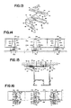
- Fig. 9 shows a bearing unit which is suitable for cutting the casing frame 1 described with reference to Fig. 8.
- the portions identical to those of the foregoing embodiment are denoted at the common numerals, and their repeated descriptions will be omitted.
- the side plate 21 is made of a hard synthetic resin such as plastics and is equipped with a metallic inner plate 55 in its inside.
- a spacer 56 made of a synthetic resin similar to that of the side plate 21 there are fitted the aforementioned metallic bearings 22 and 23 which are fixed in the spacer 56 by means of pins 57 such that they are rotatable with respect to the side plate 21.
- the traverse rod 16 and the tilt rod 12 have their end portions inserted into the receiving holes 51 of the bearings 22 and 23, respectively, and are fixed therein by the screws 52.
- the receiving holes 51 are given a depth to reach at least the spacer side of the inner plate 55 so that the traverse rod 16 and the tilt rod 12 can be inserted into the receiving holes 51 to have their end faces generally coextensive with the open end face of the casing frame 1.
- the receiving holes 51 for receiving the traverse rod 16 and the tilt rod 12 are so deepened that the casing frame 1 and the traverse and tilt rods 16 and 12 are constructed to have coextensive end faces.
- this cutting can be simplified by only one operation because the casing frame 1 and the traverse and tilt rods 16 and 12 have a common length.
- the blind is enabled to remarkably enhance its production efficiency merely by manufacturing the blind in accordance with the maximum length of the standards, for example, because it can be cut and reassembled, if necessary, without any difficulty.
- the bearings 22 and 23 can be made of not only a metal but also a synthetic resin such as plastics, if they can sufficiently endure the fixing force of the screws.
- the side plate 21, the inner plate 55 and the spacer 56 may be made of an appropriate material.
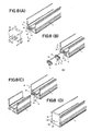
- Figs. 10 and 11 show the detail of the casing frame structure.
- reference numerals 61a and 61b denote retaining fins which are formed on the front side of the casing frame 1, i.e., at upper and lower portions of an outer wall face 62 opposed to the rod chamber 2.
- retaining fins 61a and 61b respectively, there are retained the retained legs 64a and 64b of cover brackets 63a and 63b.
- cover brackets 63a and 63b In the folded edges 65a and 65b of these cover brackets 63a and 63b, there is fitted a shield cover 66 which is extended therebetween to below the casing frame 1.
- Reference numeral 67 denotes a cord chamber which is formed at the side of the rod chamber 2 for accommodating a cord 68 or the like.
- a cover 70 is removivelyably fitted on the open top of the cord chamber 67 through fitting grooves 69.
- a drive unit chamber 71 which accommodates therein the drive units such as the motors 25 and 27 and so on for driving the traverse rod 16 and the tilt rod 12.
- the rod chamber 2 is formed in the lower portion of the casing frame 1 and offset to one side from the center line.
- the slats 14 are caused to run along the guide rails 3 on the runners 4 suspended on the line offset from the center line of the casing frame 1.
- the edge portions 14a of the slats 14 are positioned inside of the outer wall face 62 of the casing frame 1 so that the shield cover 66 can be fitted to extend downward from the casing frame 1 thereby to prevent the light without fail from breaking through a clearance A between the casing frame 1 and the slats 14.
- the cord chamber 67 which has its top closed with the cover 70, the cord 68 can be neatly arranged to wire the blind without any electric trouble.
- the drive units can be accommodated in the chamber 71 which is formed over the rod chamber 2 and the cord chamber 67 so that the blind can be made compact to give a neat appearance.
- the blind can be made more compact by accommodating the not-shown threaded rods or the like of the drive units in the cord chamber 67.
- the sizes, shapes and so on of the casing frame and the individual chambers may be appropriately selected, as shown in Fig. 11.
- the internal structure of the runner accommodating chamber which can be modified in various manners. These structures can naturally be applied not only to the blind but also to a curtain.
- the chamber 67 may be equipped therein with the drive units such as the motors 25 and 27 whereas the chamber 71 may be equipped therein with the cord 68 and so on.
- Figs. 12 to 14 show a bracket for fastening the casing frame to a support such as a wall.
- reference numeral 81 denotes a bracket body has a flattened support arm 84 extending at a right angle with respect to a mounted plate 83 which is to be mounted on the mounting face 82 of the wall or the like.
- the bracket body 81 is formed with screw holes 86 through which is mounted the mounted plate 83 on the mounting face 82 by means of screws 85.
- the aforementioned support arm 84 has its right and left side edges bent upward to form a pair of guide members 87.
- the support arm 84 is formed with a first slot 88 at its base end and with a fixing hole 89 at its extending end.
- a hanger head 90 to be slid on the upper face of the support arm 84 is constructed of a planar body 91 and a one-side clamping hook 92 extending from one side of the planar body 91.
- the hanger head 90 is formed with a second slot 93 at the base end of its planar body 91 and with an internally threaded hole 94 at its leading end.
- Reference numeral 95 denotes a hanger hook to be slid on the lower face of the support arm 84.
- This hanger hook 95 is constructed of a planar body 96 to be slidably underlaid on the lower face of the support arm 84, and a stepped clamping end 97 extending from the leading end of the planar body 96.
- This planar body 96 has its two side edges bent upward to form guide members 98 and is formed with a fixing hole 99 at its center.
- Reference numeral 100 denotes a first fixing member or bolt which is screwed through the fixing hole 99 of the hanger hook 95, the first slot 88 of the support arm 84 and the second slot 93 of the hanger head 90 into an internally threaded hole 102 of a nut 101 to be placed on the hanger head 90.
- Numeral 103 denotes a second fixing member or bolt which is screwed through the fixing hole 89 of the support arm 84 into the internally threaded hole 94 of the hanger head 90.
- Numeral 104 denotes a casing frame which is formed with one- and other-side ears 104a and 104b at the two side of its upper portion.
- first and second brackets 80a and 80b are fastend to the mounting face 82 at the two sides by means of the screws 85a and 85b.
- These first and second brackets 80a and 80b are prepared such that their one-side clamping hooks 92a and 92b are slightly protruded and such that the support arms 84a and 84b and the hanger heads 90a and 90b are fastened together by means of the second bolts 103a and 103b.
- the hanger hooks 95a and 95b are made slidable with the first bolts 100a and 100b being loosened.
- the third bracket 80c is then fastened to the mounting face 82 generally at the center between the first and second brackets 80a and 80b by means of the screws 85c. More specifically, this third bracket 80c is fastened to the mounting face 82 by the screws 85c without the first bolt 100c, namely, with the hanger hook 95c being unfixed on the bracket body 81c by the first bolt 100c. In this state, the hanger head 90c and the hanger hook 95c of the third bracket 80c are made slidable with their strokes being limited by the coextensive portions of the second and first slots 93c and 88c so that their one- and other-side clamping portions may have their widths maximized.
- the one-side ear 104a of the casing frame 104 is fitted on the fixed one-side clamping hooks 92a and 92b of the first and second brackets 80a and 80b, and the hanger hooks 95a and 95b are then moved to fit the other-end clamping ends 97a and 97b on the other-side ear 104b. Then, the hanger hooks 95a and 95b are fastened to the bracket bodies 81a and 81b by means of the first bolts 100a and 100b.
- the hanger head 90c of the third bracket 80c is moved until its one-side clamping hook 92c is fitted on the one-side ear 104a.
- the hanger hook 95c is also moved until the other-side clamping end 97c is fitted on the other-side ear 104b. If the first bolt 100 is then fastened, the hanger head 90c and the hanger hook 95c can be fastened together with the nut 101 to the support arm 84c so that the third bracket 80c can then support the casing frame 104.
- the bracket body 81 can be mounted on the mounting face 82 of the wall or the like by means of the screws 83, and the hanger head 90 and the hanger hook 95 can be adjusted independently of each other.
- the first and second brackets 80a and 80b can have their hanger heads 90a and 90b fixed in advance whereas the third bracket 80c can have its hanger head 90c adjusted freely.
- the third bracket 80c is allowed to have its one- and other-side clamping portions 92c and 97c adjusted freely so that they can be fixed on the one- and other-side ears 104a and 104b without any difficulty.
- the hanger heads 90a and 90b can be fixed in position in the first and second brackets 80a and 80b, whereas the hanger head 90c can be made slidable in the third bracket 80c.
- the first bolt 100 is loosely inserted into the first slot 88 of the support arm 84 and the second slot 93 of the hanger head 90 so that it can adjust and fix the hanger head 90 and the hanger hook 95 to predetermined lengths.
- the present invention should not be limited to the aforementioned fourth embodiment but may be modified such that the casing frame is supported by four or more brackets.
- reference numeral 111 denotes a planar bracket body which is to be mounted on an upper support face 112 such as a ceiling or a window frame.
- This bracket body 111 has its right and left side edges bent upward to form a pair of guide members 113 opposed to each other and has its one side formed with a plurality of screw holes 114 and its other side formed with a first slot 115. These screw holes 114 and first slot 115 are arranged in the longitudinal direction of the bracket body 111.
- This bracket body 111 is further formed at its one side with a fixing hole 116 which is offset from the screw holes 114.
- a hanger head 117 On the top of the bracket body 111, on the other hand, there is made slidable in the longitudinal direction a hanger head 117.
- This hanger head 117 is constructed of a planar body 118, which is laid on the top of the bracket body 111 and regulated by the guide members 113, and a one-side clamping hook 119 which extends from one side of the planar body 118.
- This planar body 118 is formed at its one side with a second slots 120, which are made partially coextensive with the screw holes 114, and with a fixing internally threaded hole 121 which is offset like the fixing hole 116.
- the other side of the planar body 118 is formed with a third slot 122 which is also made partially coextensive with the aforementioned first slot 115.
- Reference numeral 123 denotes a hanger hook which is made slidable on the lower face of the bracket body 111.
- This hanger hook 123 is constructed of a planar body 124, which is laid on the lower face of the bracket body 111, and a stepped clamping end 125 which is formed at the leading end of the planar body 124.
- this planar body 124 has its right and left side edges bent upward to form a pair of guide members 126 and is formed with a fixing hole 127 at its center.
- Reference numeral 128 denotes a first fixing member or bolt, which is screwed through the fixing hole 127 of the hanger hook 123, the first slot 115 of the bracket body 111 and the third slot 122 of the hanger head 117 into a nut 129 which is placed on the planar body 118 of the hanger head 117.
- Reference numeral 131 denotes a second fixing member or bolt, which is screwed through the fixing hole 116 into the internally threaded hole 121.
- Numeral 132 denotes fixing members or screws which are driven through the respective screw holes 114 and the second slots 120 to have their tips anchored in the upper support face 112.
- Numeral 133 denote a pair of guide rails which are formed with ears 133A and 133B at the two ends of their upper portions.
- first and second brackets 110A and 110B are fastened to the upper support face 112 at the two sides. More specifically, these brackets 110A and 110B can be mounted by slightly projecting their one-side clamping hooks 119A and 119B, by fixing the bracket bodies 111A and 111B and the hanger heads 117A and 117B by means of the second bolts 131A and 131B, and by driving the fixing screws 132A and 132B through the screw holes 114A and 114B and the second slots 120A and 120B into the upper support face 112.
- the third bracket 110C to be positioned generally at the center between the first and second brackets 110A and 110B is fastened to the upper support face 112 by the fixing screws 132C without the second bolt, namely, with the hanger head 117C being unfixed on the bracket body 111C.
- the hanger head 117C of the third bracket 110C is made slidable with a stroke limited by the length of the second slots 120 so that the spacing between the one- and other-side clamping portions 119C and 125C is set at the maximum.
- the one-side ear 133A of the guide rail 133 is fitted on the fixed one-side clamping hooks 119A and 119B of the first and second brackets 110A and 110B, and the hanger hooks 123A and 123B of the first and second brackets 110A and 110B are moved to fit their other-side clamping ends 125A and 125B on the other-side ear 133B.
- the hanger hooks 123A and 123B are fastened to the bracket bodies 111a and 111B by means of the first bolts 128A and 128B.
- the one-side clamping hook 119C of the third bracket 110C is fitted on the one-side ear 133A, and the hanger hook 123C is moved to fit its other-side clamping end 125C on the other-side ear 133B.
- the bracket body 111C, the hanger head 119C, the hanger hook 123C and the nut 129C are fastened together by means of the first bolt 128C so that the guide rails 133 can be supported by the third bracket 110C.
Landscapes
- Engineering & Computer Science (AREA)
- Structural Engineering (AREA)
- Architecture (AREA)
- Civil Engineering (AREA)
- Blinds (AREA)
Priority Applications (2)
| Application Number | Priority Date | Filing Date | Title |
|---|---|---|---|
| EP87303767A EP0288623A1 (de) | 1987-04-28 | 1987-04-28 | Elektrisch betätigbarer Vorhang |
| US07/165,720 US4878528A (en) | 1987-04-28 | 1988-03-09 | Electric blind |
Applications Claiming Priority (1)
| Application Number | Priority Date | Filing Date | Title |
|---|---|---|---|
| EP87303767A EP0288623A1 (de) | 1987-04-28 | 1987-04-28 | Elektrisch betätigbarer Vorhang |
Publications (1)
| Publication Number | Publication Date |
|---|---|
| EP0288623A1 true EP0288623A1 (de) | 1988-11-02 |
Family
ID=8197888
Family Applications (1)
| Application Number | Title | Priority Date | Filing Date |
|---|---|---|---|
| EP87303767A Withdrawn EP0288623A1 (de) | 1987-04-28 | 1987-04-28 | Elektrisch betätigbarer Vorhang |
Country Status (2)
| Country | Link |
|---|---|
| US (1) | US4878528A (de) |
| EP (1) | EP0288623A1 (de) |
Cited By (1)
| Publication number | Priority date | Publication date | Assignee | Title |
|---|---|---|---|---|
| FR2835013A1 (fr) * | 2002-01-18 | 2003-07-25 | Daniel Bracq | Dispositif destine a bloquer le tube d'enroulement d'un volet roulant mu par un moteur electrique dont l'arret est obtenu, au moins dans le sens de l'ouverture, par un obstacle a sa rotation |
Families Citing this family (29)
| Publication number | Priority date | Publication date | Assignee | Title |
|---|---|---|---|---|
| US5042553A (en) * | 1990-03-14 | 1991-08-27 | Levolor Corporation | Window blind headrail and mounting bracket |
| US5698958A (en) * | 1993-06-11 | 1997-12-16 | Harmonic Design, Inc. | Head rail-mounted actuator for window coverings |
| US5495153A (en) * | 1993-06-11 | 1996-02-27 | Harmonic Design, Inc. | Head rail-mounted mini-blind actuator for vertical blinds and pleated shades |
| US6060852A (en) * | 1993-06-11 | 2000-05-09 | Harmonic Design, Inc. | Head rail-mounted actuator for window covering |
| US5517094A (en) * | 1993-07-20 | 1996-05-14 | Harmonic Design, Inc. | Head rail-mounted mini-blind actuator |
| FR2735812B1 (fr) * | 1995-06-21 | 1997-08-22 | Somfy | Dispositif d'enroulement motorise pour stores venitiens |
| US6369530B2 (en) | 1996-09-06 | 2002-04-09 | Hunter Douglas Inc. | Battery-powered wireless remote-control motorized window covering assembly having controller components |
| US5793174A (en) * | 1996-09-06 | 1998-08-11 | Hunter Douglas Inc. | Electrically powered window covering assembly |
| US6299115B1 (en) * | 1998-06-22 | 2001-10-09 | Hunter Douglas Inc. | Remote control operating system and support structure for a retractable covering for an architectural opening |
| WO2001079647A1 (en) * | 2000-04-14 | 2001-10-25 | Wayne-Dalton Corporation | A method and apparatus for driving and storing a covering |
| US6405782B1 (en) * | 2000-11-16 | 2002-06-18 | Keng Mu Cheng | Transmission system for a motor-driven blind |
| USD464870S1 (en) | 2001-03-27 | 2002-10-29 | Hunter Douglas Inc. | Mounting bracket for coverings for architectural openings |
| US6585208B1 (en) | 2002-01-25 | 2003-07-01 | Hunter Douglas Inc. | Universal bracket for mounting coverings for architectural openings |
| US7748431B2 (en) | 2006-06-05 | 2010-07-06 | Rite-Hite Holding Corporation | Track and guide system for a door |
| US20070277943A1 (en) * | 2006-06-05 | 2007-12-06 | Rite-Hite Holding Corporation | Track and guide system for a door |
| US8037921B2 (en) | 2006-06-05 | 2011-10-18 | Rite-Hite Holding Corporation | Track and guide system for a door |
| US8193742B2 (en) | 2008-07-22 | 2012-06-05 | Hunter Douglas Inc. | Programmable motor for window coverings |
| US8307878B2 (en) | 2009-01-14 | 2012-11-13 | Hunter Douglas Inc. | Noise dampening motor drive system for retractable covering for architectural openings |
| NL1039407C2 (en) | 2012-02-27 | 2013-08-28 | Hunter Douglas Ind Bv | Architectural covering having a drive mechanism for extending and retracting a covering member between opposite first and second end positions. |
| US20150107788A1 (en) * | 2012-09-17 | 2015-04-23 | Qmotion Incorporated | Method and apparatus for linked horizontal drapery panels having varying characteristics to be moved independently by a common drive system |
| US10765247B2 (en) | 2015-09-16 | 2020-09-08 | House of Atlas, LLC | Support bracket for rod assembly |
| US20200080367A1 (en) * | 2018-09-11 | 2020-03-12 | James A. Daugaard | Roller shade/drapery mounting system |
| US11452398B2 (en) | 2020-01-22 | 2022-09-27 | House of Atlas, LLC | Bracket for surface mounting |
| US11198476B2 (en) * | 2020-03-12 | 2021-12-14 | Ford Global Technologies, Llc | Quarter panel bracket system for pillar assembly adjustment |
| US12123457B2 (en) | 2020-06-03 | 2024-10-22 | Current Products Company, LLC | Splice connector system for architectural covering support rods |
| CN111700475B (zh) * | 2020-06-28 | 2025-03-21 | 宁波森瑞机电技术有限公司 | 一种电动窗帘的驱动装置 |
| US11986118B2 (en) * | 2022-06-16 | 2024-05-21 | San Hsin Plastech Co., Ltd. | Bracket structure and method of using the bracket structure |
| US12082733B2 (en) | 2022-09-23 | 2024-09-10 | House of Atlas, LLC | Mounting bracket |
| US12251040B2 (en) | 2023-02-03 | 2025-03-18 | House of Atlas, LLC | Mounting bracket |
Citations (7)
| Publication number | Priority date | Publication date | Assignee | Title |
|---|---|---|---|---|
| US3463219A (en) * | 1966-10-10 | 1969-08-26 | Schenker Storen Maschf | Blind for windows or the like |
| CH529909A (fr) * | 1970-03-26 | 1972-10-31 | Hunter Douglas | Dispositif de commande à arbre fileté pour jalousie à lames verticales |
| US4254813A (en) * | 1979-06-20 | 1981-03-10 | Hunter Douglas International N.V. | Valance bracket for vertical venetian blind |
| US4261408A (en) * | 1979-06-13 | 1981-04-14 | Levolor Lorentzen, Inc. | Traverse cord lock for vertical blind |
| US4262728A (en) * | 1978-06-30 | 1981-04-21 | Levolor Lorentzen, Inc. | Vertical blind |
| US4306608A (en) * | 1979-04-06 | 1981-12-22 | Frentzel Kurt H | Louver carrier for louver of a vertical venetian blind |
| DE3048344A1 (de) * | 1977-02-26 | 1982-03-25 | Hans Heynau GmbH, 8000 München | Motorischer antrieb fuer lamellenjalousien mit senkrecht angeordneten lamellen |
Family Cites Families (6)
| Publication number | Priority date | Publication date | Assignee | Title |
|---|---|---|---|---|
| US3030060A (en) * | 1960-01-15 | 1962-04-17 | Breuer Karl | Curtain rod mounting devices |
| IT967195B (it) * | 1972-09-06 | 1974-02-28 | Regolux S R L | Dispositivo di comando per venezia ne o tendine in genere |
| US4222156A (en) * | 1977-12-22 | 1980-09-16 | Levolor Lorentzen, Inc. | Holder for supporting a valance at a venetian blind head |
| DE2913888C2 (de) * | 1979-04-06 | 1983-01-05 | Hunter Douglas Industries B.V., 3008 Rotterdam | Lamellenjalousie mit lotrechten Lamellen |
| US4293021A (en) * | 1979-06-06 | 1981-10-06 | Arena Joseph Philip | Support for traversing window covering device |
| US4449564A (en) * | 1981-08-27 | 1984-05-22 | Don Hansen | Adjustable track for louver drapes or blinds |
-
1987
- 1987-04-28 EP EP87303767A patent/EP0288623A1/de not_active Withdrawn
-
1988
- 1988-03-09 US US07/165,720 patent/US4878528A/en not_active Expired - Fee Related
Patent Citations (7)
| Publication number | Priority date | Publication date | Assignee | Title |
|---|---|---|---|---|
| US3463219A (en) * | 1966-10-10 | 1969-08-26 | Schenker Storen Maschf | Blind for windows or the like |
| CH529909A (fr) * | 1970-03-26 | 1972-10-31 | Hunter Douglas | Dispositif de commande à arbre fileté pour jalousie à lames verticales |
| DE3048344A1 (de) * | 1977-02-26 | 1982-03-25 | Hans Heynau GmbH, 8000 München | Motorischer antrieb fuer lamellenjalousien mit senkrecht angeordneten lamellen |
| US4262728A (en) * | 1978-06-30 | 1981-04-21 | Levolor Lorentzen, Inc. | Vertical blind |
| US4306608A (en) * | 1979-04-06 | 1981-12-22 | Frentzel Kurt H | Louver carrier for louver of a vertical venetian blind |
| US4261408A (en) * | 1979-06-13 | 1981-04-14 | Levolor Lorentzen, Inc. | Traverse cord lock for vertical blind |
| US4254813A (en) * | 1979-06-20 | 1981-03-10 | Hunter Douglas International N.V. | Valance bracket for vertical venetian blind |
Cited By (2)
| Publication number | Priority date | Publication date | Assignee | Title |
|---|---|---|---|---|
| FR2835013A1 (fr) * | 2002-01-18 | 2003-07-25 | Daniel Bracq | Dispositif destine a bloquer le tube d'enroulement d'un volet roulant mu par un moteur electrique dont l'arret est obtenu, au moins dans le sens de l'ouverture, par un obstacle a sa rotation |
| EP1331355A1 (de) * | 2002-01-18 | 2003-07-30 | Daniel Bracq | Vorrichtung zur Blockierung einer Rolladenwickelwelle |
Also Published As
| Publication number | Publication date |
|---|---|
| US4878528A (en) | 1989-11-07 |
Similar Documents
| Publication | Publication Date | Title |
|---|---|---|
| US4878528A (en) | Electric blind | |
| EP1039092B1 (de) | Modularer Betätigungsmechanismus für Abdeckungen architektonischer Öffnungen | |
| CA2243369C (en) | Dual mini-blind cutter | |
| EP0261304A2 (de) | Stellantrieb für elektrisch betätigbare Vorhänge | |
| CA2295716A1 (en) | Set of construction elements for furniture | |
| AU715082B2 (en) | A universal mounting and parallel guidance arrangement for window screening device | |
| WO2013192189A1 (en) | Window treatment having an adjustable bottom bar | |
| CN210146881U (zh) | 一种等距调节剪线模组 | |
| AU6247399A (en) | Modular horizontal window blind | |
| CA2415609A1 (en) | Slat and sieve assembly | |
| CN118727930B (zh) | 一种方便安装拆卸的钢结构网架 | |
| CN212107906U (zh) | 一种可调角度的led硬光条 | |
| US20200284089A1 (en) | Transmission for an architectural-structure covering | |
| CN213775192U (zh) | 电动百叶窗的模块化翻页卷绳器 | |
| JP7039425B2 (ja) | 建具 | |
| CN218551741U (zh) | 一种物流物品放置架 | |
| JP7195820B2 (ja) | 建具 | |
| EP3906819B1 (de) | Elektrischer vorhang | |
| EP1479846A1 (de) | Neigungsverstellbare Haltevorrichtung für eine Markise | |
| CN118299939B (zh) | 一种便于布线的配电柜 | |
| KR200273990Y1 (ko) | 소형 공작기계 복합 수납함 | |
| CN221442430U (zh) | 一种隔音百叶窗 | |
| JPH01131765U (de) | ||
| EP4234874B1 (de) | Verriegelungssystem für schieberahmen | |
| CN219004114U (zh) | 一种冷轧机的板材导向限位结构 |
Legal Events
| Date | Code | Title | Description |
|---|---|---|---|
| PUAI | Public reference made under article 153(3) epc to a published international application that has entered the european phase |
Free format text: ORIGINAL CODE: 0009012 |
|
| AK | Designated contracting states |
Kind code of ref document: A1 Designated state(s): DE FR GB |
|
| STAA | Information on the status of an ep patent application or granted ep patent |
Free format text: STATUS: THE APPLICATION IS DEEMED TO BE WITHDRAWN |
|
| 18D | Application deemed to be withdrawn |
Effective date: 19890503 |
|
| RIN1 | Information on inventor provided before grant (corrected) |
Inventor name: KOBAYASHI, MASANORI |