EP0288708B1 - Anbindevorrichtung für Rindvieh - Google Patents
Anbindevorrichtung für Rindvieh Download PDFInfo
- Publication number
- EP0288708B1 EP0288708B1 EP88103992A EP88103992A EP0288708B1 EP 0288708 B1 EP0288708 B1 EP 0288708B1 EP 88103992 A EP88103992 A EP 88103992A EP 88103992 A EP88103992 A EP 88103992A EP 0288708 B1 EP0288708 B1 EP 0288708B1
- Authority
- EP
- European Patent Office
- Prior art keywords
- crib
- tying device
- separating frame
- separating
- animal
- Prior art date
- Legal status (The legal status is an assumption and is not a legal conclusion. Google has not performed a legal analysis and makes no representation as to the accuracy of the status listed.)
- Expired - Lifetime
Links
Images



Classifications
-
- A—HUMAN NECESSITIES
- A01—AGRICULTURE; FORESTRY; ANIMAL HUSBANDRY; HUNTING; TRAPPING; FISHING
- A01K—ANIMAL HUSBANDRY; AVICULTURE; APICULTURE; PISCICULTURE; FISHING; REARING OR BREEDING ANIMALS, NOT OTHERWISE PROVIDED FOR; NEW BREEDS OF ANIMALS
- A01K5/00—Feeding devices for stock or game ; Feeding wagons; Feeding stacks
- A01K5/01—Feed troughs; Feed pails
-
- A—HUMAN NECESSITIES
- A01—AGRICULTURE; FORESTRY; ANIMAL HUSBANDRY; HUNTING; TRAPPING; FISHING
- A01K—ANIMAL HUSBANDRY; AVICULTURE; APICULTURE; PISCICULTURE; FISHING; REARING OR BREEDING ANIMALS, NOT OTHERWISE PROVIDED FOR; NEW BREEDS OF ANIMALS
- A01K1/00—Housing animals; Equipment therefor
- A01K1/0005—Stable partitions
- A01K1/0011—Cubicle partitions
Definitions
- the invention relates to a tethering device for cattle according to the preamble of claim 1.
- Devices of this type are used to equip cattle sheds to tie each animal in its assigned place in front of the crib, the animals in bays, e.g. B. in groups of two, kept separate. Partly for the sake of animal-friendly cattle husbandry, partly with a view to efficient barn operation, various and very different requirements are placed on such attachment devices.
- Known designs of such stable equipment are probably suitable for individual circumstances, but are not adaptable to different types of animals or changing operating conditions, especially with regard to the subdivision of the continuous crib to prevent mutual feed removal or the different, appropriate position of the boundary tube for different animals.
- a connecting device of the type mentioned can be equipped with vertical plates for the longitudinal division of the crib (US-A-2 221 046). These plates are hinged to the horizontal boundary tube and can be swung upwards out of the crib in a vertical plane. This arrangement requires a certain height of the boundary tube, and in addition, the plates can only be operated individually, which is cumbersome when the number is large Crib, for example for cleaning, should be released continuously.
- the object of the present invention is to create an adaptable cattle tying device of the type mentioned at the outset which meets the changing requirements mentioned above and which can also be modularly expanded in stages; in particular, if necessary, a fully effective partitioning of the feed trough between the individual bays should be possible without the continuous, convenient cleaning of the trough being hindered.
- the crib-side support post is formed at its upper end with guides accessible in the post axis for receiving the crib separating member.
- the animal divider 1 (also called “base frame”) essentially consists of a first pipe bend with the legs 2, 4, a second pipe bend 5 and a vertical support post 3 located on the side of the continuous feed crib 10. The parts mentioned and a connecting web 9 of the animal divider are firmly welded together.
- the animal separating bracket 1 (as well as additional brackets arranged at equal intervals as required) is anchored transversely to the crib 10 above the lying surface 13 of the barn, on the one hand with the vertical leg 2 and on the other hand by means of an anchor base 6 welded to the pipe bend 5, which rests on the front crib wall 11.
- the anchor base 6 is offset with respect to the crib-side support post 3, and the animal separating bracket 1 is anchored overall in such a position that the mentioned support post 3 is displaced somewhat towards the feed trough 12 with respect to the front crib wall 11.
- the support post which is preferably designed as a straight, continuous tube, is exposed at the top and bottom.
- the upper and lower tube ends form guides 22 and 23, which are accessible in the direction of the post axis 19. As explained further below, these guides serve to selectively accommodate a separating member in the area of the crib 10.
- the support post 3 serves to selectively accommodate additional parts of the barn equipment, such as a drinking bowl 14.
- the support post is expediently extended beyond the pipe leg 4 forming the upper boundary of the animal separating bracket, and the horizontal boundary pipe 7 can be attached to this extension 21 by means of a pipe clamp 8 be attached at a suitable height.
- the limiting tube 7 runs along the feed crib and connects the individual via a clamp 8 Animal divider 1 with each other.
- the animals, which are attached to the animal separating brackets 1 individually or in groups of two on each side of the bracket, are prevented by the limiting tube 7 from stepping forward against the feed crib or hurling grass and hay with sweeping head movements.
- the low-cost basic equipment of a connecting device described above with reference to FIG. 1 offers the prerequisites for further equipment as required, a modular expansion of the basic equipment being possible with extensive reuse of the same or similar parts.
- the bays can all be equipped the same or different depending on the requirements, especially with regard to crib separation and the position of the boundary tube (horizontal and vertical).
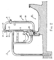
- FIG. 2 A first such variant is shown in FIG. 2.
- the animal divider 1 in the same design as in FIG. 1 is supplemented by a fixed crib divider 20.
- This consists essentially of a pipe bend 24 and a pipe section 26 which is held adjustable on the pipe bend 24 by means of a clamp 25.
- the lower end of the pipe bend 24 has a fixed pin 28 and the pipe section 26 has a pin 27 which engage from below or above in the open ends of the support post 3 with the guides 22 and 23 (FIG. 1).
- the limiting tube 7 is fastened here by means of the clamp 8 to the bracket 24, whereby (with analog attachment of the tube 7 to adjacent connecting devices or to an end post or the like) the crib separating bracket is held in its position above the crib 10.
- the clamp 8 or the pipe 7 can be clamped to the pipe bend 24 at different heights as well as optionally on the outside or inside.
- the variant according to FIG. 2 thus offers the possibility of using the simplest means to prevent mutual disturbances or injuries to the animals in the crib area and to fasten the limiting tube in an optimal position in each case.
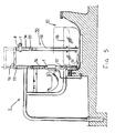
- the variant with the somewhat differently designed crib separating bracket 30 according to FIG. 3 offers expanded adjustment options for the bracket and allows it to be pivoted sideways for easier cleaning of the crib area.
- the crib separating bracket 30 is composed of a lower cross member 31 (preferably a square tube), a straight pipe section 32, a pipe bend 35, a rod 33 firmly connecting the parts 32 and 35, and a pipe section 36 which is held in an adjustable manner in a clamp 37, the Pipe piece 36 and the cross member 31 are each provided with a coaxial pin 38 and 39, respectively. Similar to FIG. 2, the pins 38 and 39 engage in the open tube ends of the post 3, but here the tube piece 36 and the lower pin 39 are somewhat longer.
- the limiting tube 7 can also be attached to the rotatable, vertical sleeve 34 in various positions, as indicated, but of course an assembly with the clamp 8 is also possible directly on the support post 3.
- a connecting armature 3a for group release which serves to be able to untie the two animals standing to the left and right of the animal separation bracket 1 at the same time.
- FIG. 4 uses essentially the same crib separating bracket 30 as shown in FIG. 3, but supplemented with a partition plate 40, which separates the feed trough practically in its entire cross section.
- a partition plate 40 which separates the feed trough practically in its entire cross section.
- Such a complete Foreclosure is important in order to ensure strict individual feeding of the animals, especially with the individual and dosed administration of short feed or high-quality concentrate.
- Such partitioning which extends to the bottom of the feed trough, would, however, hinder the lateral pivoting of the crib separating bracket when the trough is still covered with feed residues.
- the partitioning device is designed as follows:
- the partitioning plate 40 is fastened at 45 to a horizontal axis 41 which is rotatably mounted in the pipe section 32 and in a bearing block 42.
- the axis of rotation 41 carries a bevel gear 43 which meshes with a bevel gear segment 44 which in turn is fastened to the lower end of the support post 3.
- the parts 43, 44 thus form a gear, which causes the horizontal axis 41 to rotate automatically when the crib separating bracket 30 is pivoted and the partition plate 40 is thus pivoted upward.
- the gear 43, 44 is expediently designed with the transmission ratio 2: 1, so that after a 90 ° pivoting of the bracket 30, the partition plate 40 is folded up by 180 °, that is to say it stands vertically above the axis 41.
- this forcibly coupled movement can also be achieved with a differently designed transmission which connects the axis of rotation 41 to a fixed part of the system.
- the rectangular or C-shaped crib separating bracket 50 is composed of a lower cross member 51, a straight tube section 52, a rod section 53 and an upper cross member 54, the latter carrying a pin 55 and the lower cross member 51 a pin 57 coaxial therewith.
- the two pins 55 and 57 engage rotatably and axially displaceably in the corresponding guides on the support post 3.
- the limiting rod 7 is mounted on the tubular piece 34 which can be rotated above the rod section 53 by means of the clamping bracket 8. As a result, the simultaneous swiveling out of several crib separating bars 50 connected by the limiting tube 7 is also possible here.
- a partitioning plate 58 is firmly attached to the crib separating bracket 50 in the lower region. Since the distance between the lower crossmember 51 and the upper crossmember 54 is greater than the height of the support post 3, the crib separating bracket 50 together with the partitioning plate and the limiting rod 7 can be raised and lowered; the upper end position is indicated by dash-dotted lines.
- a pneumatically or hydraulically operated cylinder / piston unit 56 is expediently installed in the interior of the support post tube 3, the cylinder of which is anchored to the support post 3 and the piston rod of which upper pin 55 acts. If the crib separating bracket 50 is raised with the aid of the unit 56, the partitioning plate 58 is at a sufficient distance from the floor of the feed trough, and the partitioning bracket including the partitioning plate can then be easily pivoted to the side.
Landscapes
- Life Sciences & Earth Sciences (AREA)
- Environmental Sciences (AREA)
- Animal Husbandry (AREA)
- Biodiversity & Conservation Biology (AREA)
- Zoology (AREA)
- Birds (AREA)
- Feeding And Watering For Cattle Raising And Animal Husbandry (AREA)
- Catching Or Destruction (AREA)
- Meat, Egg Or Seafood Products (AREA)
Description
- Die Erfindung betrifft eine Anbindevorrichtung für Rindvieh gemäss dem Oberbegriff des Anspruches 1.
- Vorrichtungen dieser Art werden zur Ausrüstung von Viehställen verwendet, um jedes Tier an seinem zugewiesenen Platz vor der Futterkrippe anzubinden, wobei die Tiere in Buchten, z. B. in Zweiergruppen, voneinander getrennt gehalten werden. Teils aus Gründen einer tiergerechten Viehhaltung, teils im Hinblick auf einen rationellen Stallbetrieb werden an solche Anbindevorrichtungen mancherlei und ganz verschiedenartige Anforderungen gestellt. Bekannte Ausführungen von derartigen Stallausrüstungen sind wohl jeweils für einzelne Gegebenheiten tauglich, jedoch an unterschiedliche Tierarten oder wechselnde Betriebsbedingungen wenig anpassungsfähig, vor allem was die Unterteilung der durchgehenden Krippe zur Verhinderung gegenseitiger Futterentnahme oder die für unterschiedliche Tiere verschiedene, zweckmässige Lage des Begrenzungsrohres anbelangt.
- Eine Anbindevorrichtung der genannten Gattung kann zwecks Längsunterteilung der Krippe mit vertikalen Platten ausgerüstet werden (US-A-2 221 046). Diese Platten sind am horizontalen Begrenzungsrohr gelenkig befestigt und können in einer Vertikalebene aus der Krippe heraus nach oben geschwenkt werden. Diese Anordnung setzt eine bestimmte Höhenlage des Begrenzungsrohrs voraus, und ausserdem können die Platten nur einzeln betätigt werden, was bei einer grösseren Zahl umständlich ist, wenn die Krippe, z.B. zwecks Reinigung, durchgehend freigegeben werden soll.
- Aufgabe der vorliegenden Erfindung ist die Schaffung einer anpassungsfähigen, den genannten wechselnden Anforderungen gerecht werdenden Viehanbindevorrichtung der eingangs genannten Art, welche vor allem auch stufenweise modular ausbaubar ist; insbesondere soll bei Bedarf eine voll wirksame Abschottung des Futtertroges zwischen den einzelnen Buchten möglich sein, ohne dass indessen die durchgehende, bequeme Reinigung des Troges behindert wird.
- Diese Aufgabe wird erfindungsgemäss dadurch gelöst, dass der krippenseitige Stützpfosten an seinem oberen Ende mit in der Pfostenachse zugänglichen Führungen für die Aufnahme des Krippen-Trennorgans ausgebildet ist.
- Dank einer derartigen Gestaltung der Anbindevorrichtung lassen sich, ausgehend von einer relativ einfachen und preiswerten Grundausrüstung, überraschend vielgestaltige Ausbaustufen und -Varianten verwirklichen, die praktisch sämtliche sich bei verschiedenen Anlagen oder bei wechselnden Betriebsverhältnissen ergebenden Bedürfnisse befriedigen können. In den Ansprüchen 2 bis 18 sind bevorzugte Ausführungsformen insbesondere hinsichtlich der Krippentrennung und des Stützpfostens zur Gestaltung verschiedener Ausbauvarianten angegeben.
- Nachstehend werden Ausführungsbeispiele der erfindungsgemässen Anbindevorrichtung in verschiedenen Ausbauvarianten in Verbindung mit der Zeichnung näher erläutert. Es zeigen (jeweils in Richtung der durchgehenden Futterkrippe gesehen):
- Fig. 1
- die Grundausrüstung mit Tiertrennbügel und Begrenzungsrohr,
- Fig. 2
- die Vorrichtung nach Fig. 1 ergänzt mit einem festen Krippentrennbügel,
- Fig. 3
- eine weitere Ausbauvariante mit schwenkbarem Krippentrennbügel,
- Fig. 4
- eine Variante zu Fig. 3, bei welcher der schwenkbare Krippentrennbügel durch eine Abschottungsplatte ergänzt ist, und
- Fig. 5
- eine weitere Ausführungsform mit schwenkbarem sowie hebund senkbarem Krippentrennbügel.
- In allen Figuren sind jeweils gleiche Teile mit gleichen Bezugszahlen bezeichnet.
- In Fig. 1 ist die Grundausrüstung einer Anbindevorrichtung mit Tiertrennbügel 1 und Begrenzungsrohr 7 dargestellt. Der Tiertrennbügel 1 (auch "Grundbock" genannt) besteht im wesentlichen aus einem ersten Rohrbogen mit den Schenkeln 2, 4, einem zweiten Rohrbogen 5 und einem auf der Seite der durchgehenden Futterkrippe 10 befindlichen, vertikalen Stützpfosten 3. Die genannten Teile sowie ein Anbindesteg 9 des Tiertrennbügels sind miteinander fest verschweisst. Der Tiertrennbügel 1 (sowie je nach Bedarf weitere, in gleichen Abständen angeordnete Bügel) ist zur Futterkrippe 10 querstehend über der Liegefläche 13 des Stalles verankert, und zwar einerseits mit dem senkrecht stehenden Schenkel 2 und anderseits mittels einem am Rohrbogen 5 festgeschweissten Ankersockel 6, welcher auf der vorderen Krippenwand 11 aufliegt. Wie ersichtlich, ist der Ankersockel 6 gegenüber dem krippenseitigen Stützpfosten 3 versetzt, und der Tiertrennbügel 1 ist insgesamt in einer solchen Lage verankert, dass der genannte Stützpfosten 3 bezüglich der vorderen Krippenwand 11 etwas zum Futtertrog 12 hin verschoben ist. Dadurch liegt der Stützpfosten, welcher vorzugsweise als gerades, durchgehendes Rohr ausgebildet ist, unten und oben frei. Das obere und das untere Rohrende bilden auf diese Weise Führungen 22 bzw. 23, welche in Richtung der Pfosten-Achse 19 zugänglich sind. Wie weiter unten erläutert, dienen diese Führungen zur wahlweisen Aufnahme eines Trennorgans im Bereich der Futterkrippe 10.
- Der Stützpfosten 3 dient zur wahlweisen Aufnahme von ergänzenden Teilen der Stallausrüstung, wie beispielsweise ein Tränkebecken 14. Zweckmässigerweise ist der Stützpfosten über den die obere Begrenzung des Tiertrennbügels bildenden Rohrschenkel 4 hinaus verlängert, und an dieser Verlängerung 21 kann das horizontale Begrenzungsrohr 7 mittels einer Rohrschelle 8 auf geeigneter Höhe befestigt werden. Das Begrenzungsrohr 7 läuft längs der Futterkrippe und verbindet über jeweils eine Schelle 8 die einzelnen Tiertrennbügel 1 untereinander. Die Tiere, welche an den Tiertrennbügeln 1 einzeln oder in Zweiergruppen jeweils beidseits des Bügels angebunden sind, werden durch das Begrenzungsrohr 7 daran gehindert, gegen die Futterkrippe vorzutreten oder mit ausholenden Kopfbewegungen Gras und Heu umherzuschleudern.
- Wie anhand der nachfolgenden Figuren gezeigt wird, bietet die vorstehend anhand der Fig. 1 beschriebene, wenig aufwendige Grundausrüstung einer Anbindevorrichtung die Voraussetzungen für eine weitere Ausrüstung je nach Bedarf, wobei ein modularer Ausbau der Grundausrüstung unter weitgehender Wiederverwendung von gleichen oder ähnlichen Teilen möglich ist. Es können dabei die Buchten alle gleich oder unterschiedlich je nach Anforderungen, insbesondere bezüglich Krippentrennung und Lage des Begrenzungsrohrs (horizontal und vertikal) ausgestattet werden.
- Eine erste solche Ausbauvariante ist in Fig. 2 dargestellt. Bei dieser ist der Tiertrennbügel 1 (in gleicher Ausführung wie nach Fig. 1) durch einen festen Krippentrennbügel 20 ergänzt. Dieser besteht im wesentlichen aus einem Rohrbogen 24 und einem Rohrstück 26, welches mittels einer Klemmschelle 25 am Rohrbogen 24 einstellbar gehalten ist. Das untere Ende des Rohrbogens 24 weist einen festen Zapfen 28 und das Rohrstück 26 einen Zapfen 27 auf, welche von unten bzw. oben in die offenen Enden des Stützpfostens 3 mit den Führungen 22 und 23 (Fig. 1) eingreifen. Das Begrenzungsrohr 7 ist hier mittels der Schelle 8 am Bügel 24 befestigt, wodurch (bei analoger Befestigung des Rohres 7 an benachbarten Anbindevorrichtungen oder an einem Endpfosten oder dgl.) der Krippentrennbügel in seiner Lage über der Futterkrippe 10 festgehalten wird. Wie angedeutet, kann die Schelle 8 bzw. das Rohr 7 auf verschiedener Höhe wie auch wahlweise auf der Aussen- oder Innenseite am Rohrbogen 24 festgeklemmt werden. Somit bietet die Variante nach Fig. 2 die Möglichkeit, mit einfachsten Mitteln gegenseitige Störungen oder Verletzungen der Tiere im Krippenbereich zu verhindern und das Begrenzungsrohr in jeweils optimaler Lage zu befestigen.
- Die Variante mit dem etwas anders gestalteten Krippentrennbügel 30 nach Fig. 3 bietet erweiterte Einstellmöglichkeiten für den Bügel und erlaubt das seitliche Schwenken desselben zwecks leichterer Reinigung des Krippenbereichs. Der Krippentrennbügel 30 setzt sich zusammen aus einer unteren Traverse 31 (vorzugsweise ein Vierkantrohr), einem geraden Rohrstück 32, einem Rohrbogen 35, einer die Teile 32 und 35 fest verbindenden Stange 33, und einem in einer Klemmschelle 37 einstellbar gehaltenen Rohrstück 36, wobei das Rohrstück 36 und die Traverse 31 je mit einem koaxialen Zapfen 38 bzw. 39 versehen sind. Aehnlich wie bei Fig. 2 greifen die Zapfen 38 und 39 in die offenen Rohrenden des Pfostens 3 ein, jedoch sind hier das Rohrstück 36 und der untere Zapfen 39 etwas länger. Dies ermöglicht, durch Lösen der Klemmschelle 37 den Krippentrennbügel 30 (der mit einem Zusatzbügel 32a ergänzt sein kann) auf verschiedene Höhen einzustellen, wie mit strichpunktierten Linien angedeutet ist. Ausserdem ist das Begrenzungsrohr 7 mit der Schelle 8 nicht starr auf dem Bügel festgeklemmt, sondern auf einem Rohrstück 34, welches auf dem Stangenabschnitt 33 drehbar ist. Dadurch ist es möglich, den Krippentrennbügel 30 nach beiden Seiten um den Stützpfosten 3 zu schwenken, wobei die Zapfen 38 und 39 sich in den Pfostenführungen drehen. Indem alle gleichartigen, durch das Begrenzungsrohr 7 verbundenen Krippentrennbügel sich in Längsrichtung an die vordere Krippenwand anlegen, wird die Krippe zur bequemen Reinigung freigegeben. Auf der drehbaren, vertikalen Hülse 34 kann das Begrenzungsrohr 7 auch bei dieser Ausführung wie angedeutet in verschiedenen Lagen befestigt werden, jedoch ist natürlich auch eine Montage mit der Schelle 8 direkt am Stützpfosten 3 möglich. Am Stützpfosten 3 ist hier ausserdem eine Anbindearmatur 3a für Gruppenauslösung angebracht, welche dazu dient, die beiden links und rechts des Tiertrennbügels 1 stehenden Tiere gleichzeitig losbinden zu können.
- Die weitere Ausbauvariante nach Fig. 4 verwendet im wesentlichen den gleichen Krippentrennbügel 30 wie nach Fig. 3, jedoch ergänzt mit einer Abschottungsplatte 40, welche den Futtertrog praktisch in seinem gesamten Querschnitt trennt. Eine solche vollständige Abschottung ist wichtig, um eine strenge Einzelfütterung der Tiere zu gewährleisten, insbesondere bei individueller und dosierter Verabreichung von Kurzfutter oder hochwertigem Kraftfut ter. Eine solche bis auf den Grund des Futtertroges reichende Abschottung würde indessen das seitliche Schwenken des Krippentrennbügels bei noch mit Futterresten belegtem Trog behindern. Um jedoch das Schwenken der Bügel und damit die durchgehende bequeme Reinigung der Krippe dennoch zu ermöglichen, ist die Abschottungseinrichtung wie folgt ausgeführt:
Die Abschottungsplatte 40 ist bei 45 an einer horizontalen Achse 41 befestigt, welche im Rohrstück 32 sowie in einem Lagerbock 42 drehbar gelagert ist. An ihrem dem Stützpfosten 3 benachbarten Ende trägt die Drehachse 41 ein Kegelrad 43, welches mit einem Kegelrad-Segment 44 kämmt, welches seinerseits am unteren Ende des Stützpfostens 3 befestigt ist. Die Teile 43, 44 bilden somit ein Getriebe, welches bewirkt, dass beim Schwenken des Krippentrennbügels 30 die horizontale Achse 41 selbsttätig gedreht und damit die Abschottungsplatte 40 hochgeschwenkt wird. Zweckmässigerweise wird das Getriebe 43, 44 mit dem Uebersetzungsverhältnis 2:1 ausgeführt, so dass nach einer 90°-Schwenkung des Bügels 30 die Abschottungsplatte 40 um 180° hochgeklappt ist, dann also vertikal über der Achse 41 steht. Selbstverständlich lässt sich diese zwangsweise gekoppelte Bewegung auch mit einem anders ausgeführten Getriebe erreichen, welches die Drehachse 41 mit einem feststehenden Teil der Anlage verbindet. - Beim Ausführungsbeispiel nach Fig. 5 wird eine vollständige Abschottung des Futtertroges mit der Möglichkeit einer Freigabe der Krippe ebenfalls, jedoch mit etwas anderen Mitteln erreicht. Der rechteckige bzw. C-förmige Krippentrennbügel 50 setzt sich zusammen aus unterer Traverse 51, geradem Rohrstück 52, Stangenabschnitt 53 und oberer Traverse 54, wobei letztere einen Zapfen 55 und die untere Traverse 51 einen hierzu koaxialen Zapfen 57 trägt. Die beiden Zapfen 55 und 57 greifen drehbar sowie axial verschiebbar in die entsprechenden Führungen am Stützpfosten 3 ein. In gleicher Weise wie bei den Ausführungsformen nach Fig. 3 und 4 ist die Begrenzungsstange 7 mittels der Klemmbride 8 auf dem über dem Stangenabschnitt 53 drehbaren Rohrstück 34 montiert. Dadurch ist auch hier das gleichzeitige Ausschwenken mehrerer durch das Begrenzungsrohr 7 verbundener Krippentrennbügel 50 möglich.
- Am Krippentrennbügel 50 ist im unteren Bereich eine Abschottungsplatte 58 fest angebracht. Indem der Abstand zwischen unterer Traverse 51 und oberer Traverse 54 grösser ist als die Höhe des Stützpfostens 3, lässt sich der Krippentrennbügel 50 samt Abschottungsplatte und Begrenzungsstange 7 heben und senken; die obere Endlage ist mit strichpunktierten Linien angegeben. Zum bequemen Anheben und Absenken des Krippentrennbügels 50 (gegebenenfalls mehrere solcher Bügel gleichzeitig) dient ein zweckmässigerweise im Innern des Stützpfosten-Rohres 3 eingebautes, pneumatisch oder hydraulisch betriebenes Zylinder/Kolben-Aggregat 56, dessen Zylinder am Stützpfosten 3 verankert ist und dessen Kolbenstange auf den oberen Zapfen 55 einwirkt. Wird also der Krippentrennbügel 50 mit Hilfe des Aggregats 56 angehoben, so weist die Abschottungsplatte 58 einen ausreichenden Abstand zum Boden des Futtertroges auf, und der Trennbügel samt Abschottungsplatte lässt sich dann leicht zur Seite schwenken.
Claims (18)
- Anbindevorrichtung für Rindvieh, mit mindestens einem quer zu einer durchgehenden Futterkrippe (10) über einer Liegefläche (13) zu verankernden Tiertrennbügel (1), welcher einen krippenseitigen Stützpfosten (3) zur wahlweisen Aufnahme von ergänzenden Ausrüstungsteilen aufweist, einem längs zur Krippe verlaufenden, die Tiertrennbügel verbindenden Begrenzungsrohr (7), sowie einem Krippen-Trennorgan (20, 30, 50), wobei der Tiertrennbügel (1) bezüglich der Krippe (10) so verankert ist, dass der krippenseitige Stützpfosten (3) gegenüber der vorderen Krippenwand (11) zum Futtertrog (12) hin versetzt ist, dadurch gekennzeichnet, dass der genannte Stützpfosten (3) an seinem oberen und unteren Ende mit in der Pfostenachse (19) zugänglichen Führungen (22, 23) für die Aufnahme des Krippen-Trennorgans (20, 30, 50) ausgebildet ist.
- Anbindevorrichtung nach Anspruch 1, dadurch gekennzeichnet, dass der krippenseitige Stützpfosten (3) eine die obere Begrenzung (4) des Tiertrennbügels (1) überragende Verlängerung (21) aufweist.
- Anbindevorrichtung nach Anspruch 1 oder 2, dadurch gekennzeichnet, dass der krippenseitige Stützpfosten (3) als an beiden Enden offenes Rohr ausgebildet ist.
- Anbindevorrichtung nach einem der vorangehenden Ansprüche, dadurch gekennzeichnet, dass der Tiertrennbügel (1) einen gegenüber dem krippenseitigen Stützpfosten (3) versetzten Ankersockel (6) zur Auflage auf der vorderen Krippenwand (11) aufweist.
- Anbindevorrichtung nach Anspruch 1, gekennzeichnet durch einen Krippentrennbügel (20, 30, 50), welcher mit zwei koaxialen Zapfen (27, 28; 38, 39; 55,57) versehen ist, die von oben bzw. unten in die Führungen (22, 23) des genannten Stützpfostens (3) eingreifen.
- Anbindevorrichtung nach Anspruch 5, dadurch gekennzeichnet, dass einer der Zapfen (27, 38) in einem Rohrstück (26, 36) befestigt ist, welches einstellbar in einer Klemmschelle (25, 37) gehalten ist.
- Anbindevorrichtung nach Anspruch 5, dadurch gekennzeichnet, dass der Krippentrennbügel (30, 50) mit seinen Zapfen (38, 39; 55, 57) in den Führungen (22, 23) schwenkbar ist.
- Anbindevorrichtung nach Anspruch 5, dadurch gekennzeichnet, dass der Krippentrennbügel (50) mit seinen Zapfen (55, 57) in den Führungen (22, 23) heb- und senkbar ist.
- Anbindevorrichtung nach Anspruch 8, dadurch gekennzeichnet, dass zum Heben und Senken eine zwischen dem Krippentrennbügel (50) und dem Tiertrennbügel (1) angreifende Zylinder/Kolben-Einheit (56) vorgesehen ist.
- Anbindevorrichtung nach Anspruch 9, dadurch gekennzeichnet, dass die Zylinder/Kolben-Einheit (56) im genannten Stützpfosten (3) eingebaut ist.
- Anbindevorrichtung nach Anspruch 6, dadurch gekennzeichnet, dass der Krippentrennbügel (30) durch Lösen der Klemmschelle (37) höheneinstellbar ist.
- Anbindevorrichtung nach Anspruch 7 oder 8, dadurch gekennzeichnet, dass der Krippentrennbügel (30, 50) mit einer den Futtertrog (12) unterteilenden Abschottungsplatte (40, 58) versehen ist.
- Anbindevorrichtung nach Anspruch 12, dadurch gekennzeichnet, dass die Abschottungsplatte (40) an einer am Krippentrennbügel (30) drehbar gelagerten, horizontalen Achse (41) befestigt ist.
- Anbindevorrichtung nach Anspruch 13, dadurch gekennzeichnet, dass die Achse (41) über ein Getriebe (43, 44) mit einem feststehenden Vorrichtungsteil gekoppelt ist, um beim Schwenken des Krippentrennbügels (30) ein gleichzeitiges Schwenken der Abschottungsplatte (40) mit der horizontalen Achse (41) zu bewirken.
- Anbindevorrichtung nach Anspruch 14, dadurch gekennzeichnet, dass das Getriebe ein Kegelradgetriebe (43, 44) mit dem Uebersetzungsverhältnis 2:1 ist, dessen einer Teil (44) am Stützpfosten (3) befestigt ist.
- Anbindevorrichtung nach Anspruch 12, dadurch gekennzeichnet, dass die Abschottungsplatte (58) mit dem heb- und senkbaren Krippentrennbügel (50) fest verbunden ist.
- Anbindevorrichtung nach Anspruch 5, dadurch gekennzeichnet, dass das mit Klemmschellen (8) versehene Begrenzungsrohr (7) wahlweise am genannten Stützpfosten (3) oder am Krippentrennbügel (20, 30, 50) montierbar ist.
- Anbindevorrichtung nach Anspruch 7, dadurch gekennzeichnet, dass der Krippentrennbügel (30, 50) eine drehbare, vertikale Hülse (34) für die Aufnahme einer das Begrenzungsrohr (7) tragenden Klemmschelle (8) aufweist.
Priority Applications (1)
| Application Number | Priority Date | Filing Date | Title |
|---|---|---|---|
| AT88103992T ATE68937T1 (de) | 1987-04-01 | 1988-03-14 | Anbindevorrichtung fuer rindvieh. |
Applications Claiming Priority (2)
| Application Number | Priority Date | Filing Date | Title |
|---|---|---|---|
| CH1246/87A CH672393A5 (de) | 1987-04-01 | 1987-04-01 | |
| CH1246/87 | 1987-04-01 |
Publications (2)
| Publication Number | Publication Date |
|---|---|
| EP0288708A1 EP0288708A1 (de) | 1988-11-02 |
| EP0288708B1 true EP0288708B1 (de) | 1991-10-30 |
Family
ID=4205898
Family Applications (1)
| Application Number | Title | Priority Date | Filing Date |
|---|---|---|---|
| EP88103992A Expired - Lifetime EP0288708B1 (de) | 1987-04-01 | 1988-03-14 | Anbindevorrichtung für Rindvieh |
Country Status (4)
| Country | Link |
|---|---|
| EP (1) | EP0288708B1 (de) |
| AT (1) | ATE68937T1 (de) |
| CH (1) | CH672393A5 (de) |
| DE (1) | DE3865876D1 (de) |
Family Cites Families (3)
| Publication number | Priority date | Publication date | Assignee | Title |
|---|---|---|---|---|
| US1337926A (en) * | 1919-03-29 | 1920-04-20 | Cowmatic Corp | Manger partition |
| US2221046A (en) * | 1938-10-24 | 1940-11-12 | Ebenhard S Gandrud | Animal stall |
| DE1607109A1 (de) * | 1967-11-15 | 1970-07-09 | Brunner Peter | Schiebevorrats-Fressgitter |
-
1987
- 1987-04-01 CH CH1246/87A patent/CH672393A5/de not_active IP Right Cessation
-
1988
- 1988-03-14 DE DE8888103992T patent/DE3865876D1/de not_active Expired - Fee Related
- 1988-03-14 AT AT88103992T patent/ATE68937T1/de not_active IP Right Cessation
- 1988-03-14 EP EP88103992A patent/EP0288708B1/de not_active Expired - Lifetime
Also Published As
| Publication number | Publication date |
|---|---|
| EP0288708A1 (de) | 1988-11-02 |
| CH672393A5 (de) | 1989-11-30 |
| ATE68937T1 (de) | 1991-11-15 |
| DE3865876D1 (de) | 1991-12-05 |
Similar Documents
| Publication | Publication Date | Title |
|---|---|---|
| EP0447822B1 (de) | Liegebox-Aufstallung | |
| EP3335548A1 (de) | Melkzeug und melkstand mit einem solchen melkzeug | |
| DE69208783T2 (de) | Vorrichtung zum Ansetzen oder Abnehmen eines Milchzeuges für Tiere | |
| EP0066237A1 (de) | Erntekopf für Erntemaschinen zum Ernten von in Reihen variablen Abstands stehendem Erntegut | |
| DE3830908A1 (de) | Selbstfahrener maehdrescher mit zweigeteiltem schneidwerk | |
| DE2649797A1 (de) | Gleiswartungsmaschine fuer das nivellieren und richten von weichen und kreuzungen | |
| EP0288708A1 (de) | Anbindevorrichtung für Rindvieh | |
| DE3124347C2 (de) | Abferkelkäfig für Schweinebuchten | |
| DE2706120C3 (de) | Sauenkäfig für eine Abferkelbucht | |
| DE69603145T2 (de) | Kupplung | |
| EP1459623A2 (de) | Abtrennvorrichtung für Stallboxen zur Haltung von Tieren | |
| DE202004007874U1 (de) | Fräsvorrichtung an einem mit vertikalen Mischschnecken ausgerüsteten Futtermischwagen | |
| CH611485A5 (en) | Farrowing pen | |
| DE3313730A1 (de) | Ferkelschutzkaefig | |
| DE7120088U (de) | Abferkelbox | |
| DE2310091C3 (de) | Vorrichtung zum Füttern von Vieh | |
| DE4303270A1 (de) | ||
| DE19645264A1 (de) | Fütterungseinheit für Pferde | |
| DE804383C (de) | Tragvorrichtung fuer einen in einem Melkstand aufzuhaengenden mechanischen Haengemelker | |
| DE8702584U1 (de) | Anbindevorrichtung für Vieh | |
| DE1900502A1 (de) | Fahrbarer Tierstall | |
| DE102017103436B3 (de) | Verstellbare Trennwand für Nutztierboxen insbesondere Schweineboxen | |
| DE1127659B (de) | Schiebefressgitter fuer Rinder | |
| DE3021872A1 (de) | Schwenkgitter fuer kurzstand-viehstaelle | |
| DE202005011635U1 (de) | Liegeplatzbegrenzung |
Legal Events
| Date | Code | Title | Description |
|---|---|---|---|
| PUAI | Public reference made under article 153(3) epc to a published international application that has entered the european phase |
Free format text: ORIGINAL CODE: 0009012 |
|
| AK | Designated contracting states |
Kind code of ref document: A1 Designated state(s): AT BE CH DE FR GB IT LI NL SE |
|
| 17P | Request for examination filed |
Effective date: 19881219 |
|
| 17Q | First examination report despatched |
Effective date: 19900920 |
|
| GRAA | (expected) grant |
Free format text: ORIGINAL CODE: 0009210 |
|
| ITF | It: translation for a ep patent filed | ||
| AK | Designated contracting states |
Kind code of ref document: B1 Designated state(s): AT BE CH DE FR GB IT LI NL SE |
|
| REF | Corresponds to: |
Ref document number: 68937 Country of ref document: AT Date of ref document: 19911115 Kind code of ref document: T |
|
| GBT | Gb: translation of ep patent filed (gb section 77(6)(a)/1977) | ||
| REF | Corresponds to: |
Ref document number: 3865876 Country of ref document: DE Date of ref document: 19911205 |
|
| ET | Fr: translation filed | ||
| PLBE | No opposition filed within time limit |
Free format text: ORIGINAL CODE: 0009261 |
|
| STAA | Information on the status of an ep patent application or granted ep patent |
Free format text: STATUS: NO OPPOSITION FILED WITHIN TIME LIMIT |
|
| 26N | No opposition filed | ||
| EAL | Se: european patent in force in sweden |
Ref document number: 88103992.9 |
|
| PGFP | Annual fee paid to national office [announced via postgrant information from national office to epo] |
Ref country code: FR Payment date: 19950224 Year of fee payment: 8 |
|
| PGFP | Annual fee paid to national office [announced via postgrant information from national office to epo] |
Ref country code: GB Payment date: 19950303 Year of fee payment: 8 |
|
| PGFP | Annual fee paid to national office [announced via postgrant information from national office to epo] |
Ref country code: DE Payment date: 19950308 Year of fee payment: 8 |
|
| PGFP | Annual fee paid to national office [announced via postgrant information from national office to epo] |
Ref country code: BE Payment date: 19950315 Year of fee payment: 8 |
|
| PGFP | Annual fee paid to national office [announced via postgrant information from national office to epo] |
Ref country code: AT Payment date: 19950322 Year of fee payment: 8 |
|
| PGFP | Annual fee paid to national office [announced via postgrant information from national office to epo] |
Ref country code: CH Payment date: 19950324 Year of fee payment: 8 |
|
| PGFP | Annual fee paid to national office [announced via postgrant information from national office to epo] |
Ref country code: SE Payment date: 19950329 Year of fee payment: 8 |
|
| PGFP | Annual fee paid to national office [announced via postgrant information from national office to epo] |
Ref country code: NL Payment date: 19950331 Year of fee payment: 8 |
|
| PG25 | Lapsed in a contracting state [announced via postgrant information from national office to epo] |
Ref country code: GB Effective date: 19960314 Ref country code: AT Effective date: 19960314 |
|
| PG25 | Lapsed in a contracting state [announced via postgrant information from national office to epo] |
Ref country code: SE Effective date: 19960315 |
|
| PG25 | Lapsed in a contracting state [announced via postgrant information from national office to epo] |
Ref country code: LI Effective date: 19960331 Ref country code: CH Effective date: 19960331 Ref country code: BE Effective date: 19960331 |
|
| BERE | Be: lapsed |
Owner name: JG FARMTECHNIK Effective date: 19960331 |
|
| PG25 | Lapsed in a contracting state [announced via postgrant information from national office to epo] |
Ref country code: NL Effective date: 19961001 |
|
| GBPC | Gb: european patent ceased through non-payment of renewal fee |
Effective date: 19960314 |
|
| REG | Reference to a national code |
Ref country code: CH Ref legal event code: PL |
|
| PG25 | Lapsed in a contracting state [announced via postgrant information from national office to epo] |
Ref country code: FR Effective date: 19961129 |
|
| NLV4 | Nl: lapsed or anulled due to non-payment of the annual fee |
Effective date: 19961001 |
|
| PG25 | Lapsed in a contracting state [announced via postgrant information from national office to epo] |
Ref country code: DE Effective date: 19961203 |
|
| EUG | Se: european patent has lapsed |
Ref document number: 88103992.9 |
|
| REG | Reference to a national code |
Ref country code: FR Ref legal event code: ST |
|
| PG25 | Lapsed in a contracting state [announced via postgrant information from national office to epo] |
Ref country code: IT Free format text: LAPSE BECAUSE OF NON-PAYMENT OF DUE FEES;WARNING: LAPSES OF ITALIAN PATENTS WITH EFFECTIVE DATE BEFORE 2007 MAY HAVE OCCURRED AT ANY TIME BEFORE 2007. THE CORRECT EFFECTIVE DATE MAY BE DIFFERENT FROM THE ONE RECORDED. Effective date: 20050314 |