EP0288815B2 - Abdichtungssystem an einem förderergestützten Vakuumtisch für eine Schneidvorrichtung - Google Patents
Abdichtungssystem an einem förderergestützten Vakuumtisch für eine Schneidvorrichtung Download PDFInfo
- Publication number
- EP0288815B2 EP0288815B2 EP88105801A EP88105801A EP0288815B2 EP 0288815 B2 EP0288815 B2 EP 0288815B2 EP 88105801 A EP88105801 A EP 88105801A EP 88105801 A EP88105801 A EP 88105801A EP 0288815 B2 EP0288815 B2 EP 0288815B2
- Authority
- EP
- European Patent Office
- Prior art keywords
- conveyor
- belt
- sections
- endless
- mat
- Prior art date
- Legal status (The legal status is an assumption and is not a legal conclusion. Google has not performed a legal analysis and makes no representation as to the accuracy of the status listed.)
- Expired - Lifetime
Links
Images




Classifications
-
- B—PERFORMING OPERATIONS; TRANSPORTING
- B26—HAND CUTTING TOOLS; CUTTING; SEVERING
- B26D—CUTTING; DETAILS COMMON TO MACHINES FOR PERFORATING, PUNCHING, CUTTING-OUT, STAMPING-OUT OR SEVERING
- B26D7/00—Details of apparatus for cutting, cutting-out, stamping-out, punching, perforating, or severing by means other than cutting
- B26D7/20—Cutting beds
-
- B—PERFORMING OPERATIONS; TRANSPORTING
- B25—HAND TOOLS; PORTABLE POWER-DRIVEN TOOLS; MANIPULATORS
- B25B—TOOLS OR BENCH DEVICES NOT OTHERWISE PROVIDED FOR, FOR FASTENING, CONNECTING, DISENGAGING, OR HOLDING
- B25B11/00—Work holders not covered by any preceding group in the subclass, e.g. magnetic work holders, vacuum work holders
- B25B11/005—Vacuum work holders
-
- B—PERFORMING OPERATIONS; TRANSPORTING
- B26—HAND CUTTING TOOLS; CUTTING; SEVERING
- B26D—CUTTING; DETAILS COMMON TO MACHINES FOR PERFORATING, PUNCHING, CUTTING-OUT, STAMPING-OUT OR SEVERING
- B26D7/00—Details of apparatus for cutting, cutting-out, stamping-out, punching, perforating, or severing by means other than cutting
- B26D7/01—Means for holding or positioning work
- B26D7/018—Holding the work by suction
-
- Y—GENERAL TAGGING OF NEW TECHNOLOGICAL DEVELOPMENTS; GENERAL TAGGING OF CROSS-SECTIONAL TECHNOLOGIES SPANNING OVER SEVERAL SECTIONS OF THE IPC; TECHNICAL SUBJECTS COVERED BY FORMER USPC CROSS-REFERENCE ART COLLECTIONS [XRACs] AND DIGESTS
- Y10—TECHNICAL SUBJECTS COVERED BY FORMER USPC
- Y10S—TECHNICAL SUBJECTS COVERED BY FORMER USPC CROSS-REFERENCE ART COLLECTIONS [XRACs] AND DIGESTS
- Y10S83/00—Cutting
- Y10S83/929—Particular nature of work or product
- Y10S83/952—Moving work
-
- Y—GENERAL TAGGING OF NEW TECHNOLOGICAL DEVELOPMENTS; GENERAL TAGGING OF CROSS-SECTIONAL TECHNOLOGIES SPANNING OVER SEVERAL SECTIONS OF THE IPC; TECHNICAL SUBJECTS COVERED BY FORMER USPC CROSS-REFERENCE ART COLLECTIONS [XRACs] AND DIGESTS
- Y10—TECHNICAL SUBJECTS COVERED BY FORMER USPC
- Y10T—TECHNICAL SUBJECTS COVERED BY FORMER US CLASSIFICATION
- Y10T83/00—Cutting
- Y10T83/748—With work immobilizer
Definitions
- the invention relates to a sealing system for a conveyor table of a cutting machine for cutting vacuum clamped laminar material, with an endless conveyor driven by wheels and formed by a plurality of successive sections linked together and meshing with the wheels, said sections being parts of a vacuum system and bearing bristle mats forming a penetrable and air-permeable cutting bed for feeding said laminar material held by vacuum in and from the working area of the table.
- a further object of the invention is a sealing system on the feed side of the conveyor the endless belt is held by axles which are anchored to the stationary frame of the table and arranged at the beginning of the curvature of the conveyor, whereby various bands are attached by one of their edges to said belt, the length of said bands is slightly greater than the width of the section of the conveyor (width of the moving conveyor table); that the width of these bands is such that at any given moment a section opens its mat at the beginning of the curvature of the conveyor this mat is blocked by one of these bands against atmosphere, and that these bands are leaving the vertical slides between the sections when these sections are passing from the curved area into the upper flat area.
- a further object of the invention is a sealing system on the flattening aera or the feed end of the conveyor table where the collection area is situated.
- the sealing system comprises of an endless belt made of flexible material and with a considerably larger extension than the space between axles, which means that once the belt is in position, it is completely slack.
- the first axle is located at a couple of slabs before the curvature commences, and next to the collection comb placed in the fixed frame of the cutting table.
- the second axle is in a horizontal plane with respect to the first, after passing the curvature. Both are at a short distance on the flat surface defined by the mat.
- one part of the belt will enter the first opening between adjacent sections which has a depression, thus avoiding vacuum leakage. It will accompany that section until a new section opens and with its losses, makes the vacuum drop in the first covered section, releasing the belt and closing the new leakage section.
- movable belts are placed towards both ends of the working area of the conveyor table and acting in synchronism with the movement of the endless conveyor, one end of the belt is anchored in the inner area of the cutting table and the other end is mobile, whereby its position is being determined by the movement of an actuator in such a way that depending on the position of the actuator the belt is taut and being separated from the surface of the mats avoiding intereference while the conveyor is moving or slack and allowing the belt to enter the leakage section between adjacent sections of the conveyor when turning into and out of the horizontal working area.
- the band of the belt is anchored to the inner area of the table near the collection comb and the other end is mobile, according to the position of a pneumatic cylinder, or some other system.
- the band is either taut, coming away from the mat surface, or slack, allowing the band to enter the leakage section. Inserting the band in the opening is guaranteed by a bar which runs on the band resting on the mat; as soon as the bar finds the opening, it will drop and drag the band with it, which will adhere to the leakage front, thereby sealing it.
- the cylinder tightens the band which, by being at a certain positive incline with respect to the horizontal of the mat, means that the bar returns to the position furthest back.
- the sealing system releases the band which falls on the mat and the bar is set into operation again, and dragging to enter in the next present opening of the conveyor.
- FIG. 1 is a general view of the cutting machine where this invention is applied, and which is disclosed hereinbelow.
- a pile of laminar material 12 -fabrics or the like - is fed through a coupling area 24 and is made to move forward through a conveyor 14.
- the cut parts 18 of the material are removed from the table in area 26 and even in the part adjacent to the conveyor.
- the geometry of the cut parts 18 is achieved by suitably moving, a bridge 1 or "X"-carriage and a "Y"-carriage 2 mounted to the bridge.
- a controller 3 regulates these movements by driving the motors - not shown - of X- and Y-carriages.
- Carriage 2 has a not shown cutting tool suitable for the material being worked on.
- Figure 2 is a more or less diagrammatic illustration of the conveyor table on which the material to be cut runs and rests by the X-Y-carriages under numerical control by the controller not shown in the Figure for reasons of clarity.
- the outer surface of the conveyor is made up of slabs 5 or sections joined to the links of a chain 10 which enmesh in wheels 13 one of which is coupled to the motor 16 which generates the forward motion.
- the chains - one at each longitudinal side of the table - are guided by straight guides 19 and curved guides 21.
- the laminar material 12 is supplied by the coupling area 24 from the flattening table 4 and once cut, is removed through area 26.
- a vacuum is generated by a pump 29 communicating with a central suction chamber 31.
- This stationary chamber communicates the vacuum to the slabs 5 through relevant openings.
- European application no. 87118526.0 "Improvements in a cutting table with vacuum clamping" by the same applicants.
- Figure 3 shows a cross-section by lines 3-3 of Figure 2, defining generally by reference numeral 5 the slab formed by a hollow box 34, closed at its ends by caps 37 and a plate 40.
- Figure 4 shows a plan view of the assembly according to the invention after removing its cover plates.
- rollers 50 are mounted and roll on the end parts 40 of the slabs when the conveyor table moves. This movement is transmitted to the axle 58 through equal pulleys 54 and belts 55.
- An endless belt 64 is placed between this axle and another axle 60, to which belt multiple bands 65 are fastened by one of their edges.
- the length of these bands 65 is slightly greater than the area of the mat 43, i.e., they are able to cover the whole open frontside 45.
- the diameter of the axle 58 in contact with the belt 64 is equal to that of the roller 50, whereby a linear displacement speed of the endless belt is obtained, equal to that of the conveyor table.
- Axles 58 and 60, the roller 50 and the endless belt 64 can also be seen in Figure 5.
- the illustrated gaskets 70 avoid vacuum leakage downwards between the boxes 34.
- the layout of one of the bands 65 which is specified with number 80 closes the front of the mat 43, adhered to it by the existing vacuum generated by pump 29.
- the width of these bands is sufficient to close all the surface open to the atmosphere.
- the band 80 tends to go upwards by the movement transmitted through the roller 50 and belt 55 to the axle 58, but when it does so, the communication of the vacuum to the next slab will ensure that it is the band 82 which closes, and in subsequent steps it will occupy the position now occupied by band 80, thereby establishing an uninterrupted closing system, which guarantees the horizontal sealing of the conveyor table.
- the bands placed in the bottom part of the belt 64 and included between 80 and 82 avoid leakage through the top of the mat.
- the mat area under the frame 24, not closed by the aforementioned bands, is blocked by a band 102 fixed by the support pipe 100 to the structure. This band rubs the mat when the table is moving and always adheres to it by the existing vacuum. Outside the frame 24, it is the fabric 12 laying on the conveyor table which avoids leakage by the upper surface.
- Figure 6 shows the closing system for the collection area which moves in the direction indicated by arrow 110.
- the situation of the chain and slabs is similar to that illustrated in Figure 5, except that the wheel 13 is the drive wheel.
- Under the frame 26 there is an endless belt 120 with its bearing rollers 122. In the position shown, it is the front side 124, which closes and the band 120 adheres there by the existing vacuum, as well as in the upper part 126, thus sealing the boxes of the conveyor.
- Figure 7 illustrates a situation following that shown in Figure 6; it is now the front wheel section 13 which is blocked and a more reduced surface 126 than before. The rest of the endless belt 120 is slack.
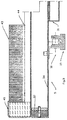
- Figures 8 and 9 show another preferred embodiment for blocking the collection side of the table and Figure 8 is the plan view of the invention, after removing the covering frame.
- the other end of the band is secured by a pipe 145 linked to connecting rods 148, which can be moved by cylinders 150.
- a bar 154 which runs on the band 140 and the mats 43, in order to enter the first opening it finds, makes a horizontal sweep, pushed by the stubs 160 connected to belts 164.
- Pulleys 168 which turn in the direction marked by arrow 170, move the belts 164, these pulleys being mechanically or electronically synchronized with the moving of the conveyor table.
- Figure 9 shows the two working positions of the described assembly.
- the connecting rod 148 driven by the cylinder 150, leaves the band 140 slack, and the bar 154 forces the band into the opening.
- the bar has moved forward towards the opening, pushed by the stubs 160.
- the connecting rod occupies the position 148', tightening the band 140' and making the bar move back to position 154', so that there is no interference with the boxes of the conveyor in their movement.
Landscapes
- Engineering & Computer Science (AREA)
- Mechanical Engineering (AREA)
- Forests & Forestry (AREA)
- Life Sciences & Earth Sciences (AREA)
- Treatment Of Fiber Materials (AREA)
- Details Of Cutting Devices (AREA)
- Machine Tool Units (AREA)
- Jigs For Machine Tools (AREA)
- Flanged Joints, Insulating Joints, And Other Joints (AREA)
- Attitude Control For Articles On Conveyors (AREA)
- Encapsulation Of And Coatings For Semiconductor Or Solid State Devices (AREA)
- Auxiliary Devices For And Details Of Packaging Control (AREA)
- Plural Heterocyclic Compounds (AREA)
- Heterocyclic Carbon Compounds Containing A Hetero Ring Having Oxygen Or Sulfur (AREA)
- Nitrogen Condensed Heterocyclic Rings (AREA)
- Belt Conveyors (AREA)
Claims (8)
- Anordnung zum Abdichten eines Endlosförderers (14), der den Schneidtisch einer ein Vakuumsystem enthaltenden Schneidmaschine bildet und eine Vielzahl von miteinander über Ketten (10) verbundenen Plattenabschnitten (10) umfaßt, wobei die Retten mittels geraden und gebogenen Führungen (19 bzw. 21) geführt sind und mit über einen Motor (16) angetriebenen Antriebsrädern (13) in Eingriff stehen, wobei jeder Plattenabschnitt (5) einen Kasten (34) beinhaltet , der mit dem Vakuumsystem in Verbindung steht, wobei auf der Oberseite des Kasten (34) eine Borstenauflage (43) aufliegt, die eine durchdringbare und luftdurchlässige Arbeitsfläche bildet, auf der Materiallagen durch das Vakuum auf dem Endlosförderer gehalten werden, und die das Material der Arbeitsfläche des Schneidtisches zuführt und von dieser abnimmt, dadurch gekennzeichnet, daß die Abdichtmittel synchron zum Vorschub des Endlosförderers (14) der Abdichteinrichtung im Bereich der beiden Enden (24,26) der Arbeitsfläche des Schneidtisches angeordnet sind und als bewegbare Endlosbänder (64,65,82;120, 122, 140) ausgebildet sind, die in die Öffnung zwischen benachbarten Plattenabschnitten (5) der Fördervorrichtung (14) beim Einlaufen in die horizontale Arbeitsfläche des Schneidtischesches (4) und bei deren Verlassen bewegbar sind und die Öffnung gegenüber der Atmosphäre luftdicht abdichten.
- Anordnung nach Anspruch 1, dadurch gekennzeichnet, daß das der Einlaufseite (24) des Endlosförderers (14) zugeordnete Endlosband (64) über am Anfang des Umlenkbereiches des Endlosförderers angeordnete, rahmenfeste Achsen (58, 60) gehalten ist, daß mehrere gegenüber der Breite des Plattenabschnittes (5) breitere Bänder (65) mit jeweils einer Kante am Endlosband (64) angeordnet sind, daß die Länge der Bänder (65) größer als die Breite der Plattenabschnitte (5) (Breite des förderergestützten Schneidtisches) derart gewählt ist, daß zu jeder Zeit beim Öffnen der Borstenauflage (43) des Endlosförderers beim Einlaufen in den Umlenkbereich ein Verschließen der Plattenabschnitte gegenüber der Atmosphäre durch eines der Bänder erfolgt, und daß diese Bänder (65) aus den senkrechten Öffnungen zwischen den Plattenabschnitten abheben, sobald diese Plattenabschnitte des Endlosförderers aus dem Umlenkbereich in den oberen ebenen Bereich des Schneidtisches laufen.
- Anordnung nach Anspruch 2, dadurch gekennzeichnet, daß für den synchronen Vorschub von Endlosband (64) und Endlosförderer (14) ein über rahmenfeste Rollen (50) getriebener Übertragungsriemen (55) vorgesehen ist, der mit der Antriebswelle (58) des Endlosbandes gekuppelt ist, und daß die Rollen (50) auf dem ebenen Teil der Endbereiche der Plattenabschnitte (5) aufsitzen und auf diesen zwecks Übertragung der Bewegung beim Vorschub des Endlosförderers (14) auf das Endlosband (64) abrollen.
- Anordnung nach Anspruch 1, dadurch gekennzeichnet, daß das der Ablaufseite (26) zugeordnete Endlosband (120), an der die Plattenabschnitte (5) des Endlosförderers (14) von oben nach unten laufen, aus biegsamem Material gleicher Breite wie der gegenüber der Atmosphäre abzudichtende Plattenabschnitt (5) besteht und wesentlich länger ist als der Abstand zwischen den das Band (120) tragenden Achsen (122), wobei die erste Achse (122) so dicht wie möglich am Rahmen der Ablaufseite (26) und etwas oberhalb der Borstenauflage (43) angeordnet ist, und daß die zweite Achse in einer in bezug auf die erste Achse annähernd horizontalen Ebene und am Ende des Umlenkbereiches angeordnet ist.
- Anordnung nach Anspruch 4, dadurch gekennzeichnet, daß die Länge des Bandes (120) derart gewählt ist, daß das Band (120) an der ebenen Oberseite der Borstenauflage eines Plattenabschnittes (5), der sich zwischen der ersten Achse und der Öffnung der Borstenauflage zum Beginn der Umlenkung des in den offenen Bereich gelangenden Endlosförderers befindet, aufliegen kann.
- Anordnung zum Abdichten eines Endlosförderers (14), der den Schneidtisch einer ein Vakuumsystem enthaltenden Schneidmaschine bildet und eine Vielzahl von miteinander über Ketten (10) verbundene Plattenabschnitte (10) umfaßt, wobei die Ketten mittels geraden und gebogenen Führungen (19 bzw. 21) geführt sind und mit über einen Motor (16) angetriebenen Antriebsrädern (13) in Eingriff stehen, wobei jeder Plattenabschnitt (5) einen Kasten (34) beinhaltet, der mit dem Vakuumsystem in Verbindung steht, wobei auf der Oberseite des Kastens (34) eine Borstenauflage (43) aufliegt, die eine durchdringbare und luftdurchlässige Arbeitsfläche bildet, auf der Materiallagen durch das Vakuum auf dem Endlosförderer gehalten werden, und die das Material der Arbeitsfläche des Schneidtisches zuführt und von dieser abnimmt, dadurch gekennzeichnet, daß die Abdichteinrichtungen synchron zum Vorschub des Endlosförderers (14) arbeiten und als bewegliche in den Endbereichen der Arbeitsfläche angeordnete Bänder (140, 140') ausgebildet sind, wobei ein Ende des Bandes (140) im Innenbereich (135) des Schneidtisches (4) starr befestigt ist und das andere Ende (148) in Abhängigkeit von der Stellung eines Stellgliedes (150) derart bewegbar ist, daß das Band (140) entweder gespannt und von der Oberfläche der Borstenauflage abgehoben ist, um eine ungehinderte Bewegung des Endlosförderers zuzulassen, oder durchhängt, damit das Band in die offene Spalte zwischen benachbarten Plattenabschnitten (5) des Endlosförderers beim Einlaufen in die oder beim Verlassen aus der horizontalen Arbeitsfläche bewegbar sind, um die Spalte gegenüber der Atmosphäre luftdicht abzudichten.
- Anordnung nach Anspruch 6, dadurch gekennzeichnet, daß den Bändern jeweils ein Stab (154) kleinen Durchmessers, aber ausreichender Festigkeit zugeordnet ist, der durch Abrollen auf der Bandinnenseite in gespanntem Zustand auf der Borstenauflage in die jeweils erste zugeordnete Öffnung zwischen zwei benachbarten Plattenabschnitten fällt und dabei das zugeordnete Band mitnimmt, so daß die Borstenauflage des jeweiligen Plattenabschnittes (5) gegenüber der Atmosphäre abgedichtet ist.
- Anordnung nach den Ansprüchen 6 und 7, dadurch gekennzeichnet daß zwei weitere endlose Riemen (164), jeweils einer an jeder Seite des Schneidtisches (4), angeordnet sind, daß der Abstand zwischen den die Riemen (164) tragenden Achsen gleich der Breite der zwischen zwei benachbarten Plattenabschnitten des Endlosförderers (14) entstehenden Zwischenräume ist, daß die erste Achse dicht am oberen Ende des Endlosförderers angeordnet ist und die zweite etwa im Umlenkbereich, daß die Riemen (164) synchron mit dem Endlosförderer (14) angetrieben sind und daß an der Außenseite jedes Riemens sich exakt gegenüberliegende Stummel (160) vorgesehen sind, mittels denen der Stab (154) über das auf der Borstenauflage aufliegende Band mitnehmbar ist, bis dieser und das Band in eine Öffnung zwischen zwei Plattenabschnitten des Endlosförderers fallen, daß die die Riemen treibenden Riemenscheiben (168) mit ihrer Durchmesser-Ebene etwa oberhalb der ebenen Fläche der Borstenauflage (43) liegen, aber unterhalb der Ebene der Bänder in ihrer gespannten Stellung, so daß jeder Stab (154) in der abgesenkten Stellung mit den Stummeln nicht in Berührung kommt, wenn diese den jeweiligen Öffnungsbereich zwischen zwei benachbarten Plattenabschnitten (5) des Endlosförderers (14) überfahren.
Priority Applications (1)
| Application Number | Priority Date | Filing Date | Title |
|---|---|---|---|
| AT88105801T ATE77425T1 (de) | 1987-04-15 | 1988-04-12 | Abdichtungssystem an einem foerderergestuetzten vakuumtisch fuer eine schneidvorrichtung. |
Applications Claiming Priority (2)
| Application Number | Priority Date | Filing Date | Title |
|---|---|---|---|
| ES8701109 | 1987-04-15 | ||
| ES8701109A ES2008120A6 (es) | 1987-04-15 | 1987-04-15 | Sistema de estanqueizacion del flujo horizontal en una mesa transportadora de material laminar con sujecion por vacio. |
Publications (3)
| Publication Number | Publication Date |
|---|---|
| EP0288815A1 EP0288815A1 (de) | 1988-11-02 |
| EP0288815B1 EP0288815B1 (de) | 1992-06-17 |
| EP0288815B2 true EP0288815B2 (de) | 1995-08-02 |
Family
ID=8250484
Family Applications (1)
| Application Number | Title | Priority Date | Filing Date |
|---|---|---|---|
| EP88105801A Expired - Lifetime EP0288815B2 (de) | 1987-04-15 | 1988-04-12 | Abdichtungssystem an einem förderergestützten Vakuumtisch für eine Schneidvorrichtung |
Country Status (10)
| Country | Link |
|---|---|
| US (1) | US5001954A (de) |
| EP (1) | EP0288815B2 (de) |
| JP (1) | JP2675059B2 (de) |
| AT (1) | ATE77425T1 (de) |
| CA (1) | CA1320224C (de) |
| DE (1) | DE3872043T2 (de) |
| DK (1) | DK167696B1 (de) |
| ES (1) | ES2008120A6 (de) |
| FI (1) | FI88122C (de) |
| IE (1) | IE61293B1 (de) |
Families Citing this family (16)
| Publication number | Priority date | Publication date | Assignee | Title |
|---|---|---|---|---|
| US5189936A (en) * | 1991-04-05 | 1993-03-02 | Gerber Garment Technology, Inc. | Conveyor for supporting and advancing sheet material and cutting machine including such conveyor |
| DE4118194A1 (de) * | 1991-06-03 | 1993-02-11 | Bullmer Spezialmaschinen Gmbh | Zuschneidevorrichtung fuer flachmaterial wie stoffe, folien oder dergleichen |
| JP2547681B2 (ja) * | 1991-09-06 | 1996-10-23 | 株式会社島精機製作所 | 自動裁断機における裁断支持面用ブラシ取付構造 |
| US5241733A (en) * | 1991-09-10 | 1993-09-07 | Geber Garment Technology, Inc. | Method of making a cloth cutter bristle bed from elongate support members |
| US5228554A (en) * | 1991-09-20 | 1993-07-20 | Gerber Garment Technology, Inc. | Material take-off ramp and system for a conveyor cutter bed and method of use |
| JP2897016B2 (ja) * | 1991-10-08 | 1999-05-31 | 株式会社島精機製作所 | 自動裁断機におけるリーク防止装置 |
| US5596917A (en) * | 1994-02-18 | 1997-01-28 | Gerber Garment Technology, Inc. | Apparatus for conveying and cutting sheet material on a vacuum bed with system for sealing end portions of the bed |
| US6050164A (en) * | 1998-07-15 | 2000-04-18 | Gerber Technology, Inc. | Adjustable resealer |
| US6175776B1 (en) * | 1998-07-15 | 2001-01-16 | Gerber Technology, Inc. | Side and edge seal for minimizing vacuum losses from a permeable support surface |
| DE10221956C1 (de) * | 2002-05-17 | 2003-08-14 | Maka Max Mayer Maschb Gmbh | Arbeitstisch von CNC- und BAZ-Maschinen |
| US20050034576A1 (en) * | 2003-08-11 | 2005-02-17 | Ray Theodore M. | Bun slicer |
| JP4757777B2 (ja) * | 2006-11-09 | 2011-08-24 | 株式会社島精機製作所 | 裁断機 |
| EP2210836B1 (de) * | 2007-11-07 | 2013-07-17 | Shima Seiki Mfg., Ltd | Fördertisch einer schneidmaschine |
| DE102015109740A1 (de) * | 2015-06-18 | 2016-12-22 | Trumpf Werkzeugmaschinen Gmbh + Co. Kg | Maschine zur trennenden Bearbeitung von plattenförmigen Materialen |
| ES2738177A1 (es) * | 2018-07-20 | 2020-01-20 | Open Mind Ventures S L U | Mesa de vacío para máquinas de corte |
| FR3111836B1 (fr) * | 2020-06-24 | 2022-07-08 | Lectra | Convoyeur de coupe à aspiration d’une machine de coupe automatique par lame de matériaux en feuilles |
Family Cites Families (7)
| Publication number | Priority date | Publication date | Assignee | Title |
|---|---|---|---|---|
| US3765289A (en) * | 1971-01-15 | 1973-10-16 | Gerber Garment Technology Inc | Vacuum hold-down apparatus |
| GB1494325A (en) * | 1973-11-23 | 1977-12-07 | Emf Corp | Conveyor system |
| US4528878A (en) * | 1981-12-28 | 1985-07-16 | Gerber Garment Technology, Inc. | Method and apparatus for holding sheet material on a sectioned vacuum bed |
| US4434691A (en) * | 1982-04-12 | 1984-03-06 | Gerber Garment Technology, Inc. | Method and apparatus for sealing cut sheet material |
| US4476756A (en) * | 1982-04-12 | 1984-10-16 | Gerber Garment Technology, Inc. | Apparatus for working limp sheet material on a conveyor |
| US4572357A (en) * | 1984-01-26 | 1986-02-25 | Gerber Garment Technology, Inc. | Sheet material conveyor with unloading apparatus |
| US4542673A (en) * | 1984-07-03 | 1985-09-24 | Gerber Garment Technology, Inc. | Apparatus for sealing cut sheet material |
-
1987
- 1987-04-15 ES ES8701109A patent/ES2008120A6/es not_active Expired
-
1988
- 1988-04-12 AT AT88105801T patent/ATE77425T1/de not_active IP Right Cessation
- 1988-04-12 EP EP88105801A patent/EP0288815B2/de not_active Expired - Lifetime
- 1988-04-12 DE DE3872043T patent/DE3872043T2/de not_active Expired - Lifetime
- 1988-04-13 CA CA000563979A patent/CA1320224C/en not_active Expired - Fee Related
- 1988-04-14 FI FI881740A patent/FI88122C/fi not_active IP Right Cessation
- 1988-04-14 IE IE112388A patent/IE61293B1/en not_active IP Right Cessation
- 1988-04-14 DK DK205588A patent/DK167696B1/da not_active IP Right Cessation
- 1988-04-14 JP JP63094403A patent/JP2675059B2/ja not_active Expired - Lifetime
- 1988-04-15 US US07/181,818 patent/US5001954A/en not_active Expired - Lifetime
Also Published As
| Publication number | Publication date |
|---|---|
| FI88122B (fi) | 1992-12-31 |
| ATE77425T1 (de) | 1992-07-15 |
| FI881740L (fi) | 1988-10-16 |
| EP0288815A1 (de) | 1988-11-02 |
| IE61293B1 (en) | 1994-10-19 |
| CA1320224C (en) | 1993-07-13 |
| DE3872043T2 (de) | 1996-05-15 |
| EP0288815B1 (de) | 1992-06-17 |
| FI88122C (fi) | 1993-04-13 |
| JP2675059B2 (ja) | 1997-11-12 |
| ES2008120A6 (es) | 1989-07-16 |
| FI881740A0 (fi) | 1988-04-14 |
| IE881123L (en) | 1988-10-15 |
| DE3872043D1 (de) | 1992-07-23 |
| DK205588D0 (da) | 1988-04-14 |
| US5001954A (en) | 1991-03-26 |
| DK167696B1 (da) | 1993-12-06 |
| JPS63278794A (ja) | 1988-11-16 |
| DK205588A (da) | 1988-10-16 |
Similar Documents
| Publication | Publication Date | Title |
|---|---|---|
| EP0288815B1 (de) | Abdichtungssystem an einem förderergestützten Vakuumtisch für eine Schneidvorrichtung | |
| EP0507327B1 (de) | Förderer zum Tragen und Befördern von Flachmaterial | |
| US4730526A (en) | Conveyorized vacuum table for feeding sheet material | |
| US4646911A (en) | Conveyorized vacuum table for feeding sheet material | |
| EP0271116B2 (de) | Schneidtisch mit Vakuum-Ansaugung | |
| EP0542410B1 (de) | Stoffabnahmerampe und System für Förderer und Schneideinrichtung und Verfahren zur Nutzung | |
| US6050065A (en) | Packaging machine | |
| EP0770037B1 (de) | Verfahren und maschine zur herstellung einer federkernmatratze,sowie feder kernmatratze | |
| US5950404A (en) | Apparatus for packing articles | |
| US6416453B1 (en) | Seal bar mechanism for bag machines | |
| US4500022A (en) | Device for severing blanks of a batch of die cut sheets | |
| DE4204756A1 (de) | Verfahren zur kontinuierlichen bzw. abschnittsweise kontinuierlichen raeumlichen trennung textiler gutteilstapel und dem sie umgebenden abfall | |
| GB2071062A (en) | Conveying webs intermittently through transverse bias cutter | |
| US3579407A (en) | Machine for heat sealing continuously moving work-material sheeting in the manufacture of bags of plastics materials | |
| GB2157272A (en) | Interrupting flow of sheets to a stack | |
| JPH0815714B2 (ja) | 積層物の裁断装置 | |
| CN111703663A (zh) | 一种卷纸包装机 | |
| EP0315600A2 (de) | Vorrichtung zum Bewegen von Asbestzementplatten | |
| SU1698068A1 (ru) | Укладчик-разгрузчик керамических изделий | |
| EP0635427B1 (de) | Vorrichtung für die Bildung und das Anbringen eines Verschlussstreifens zum Schliessen der Öffnung eines gefüllten Sackes | |
| ITBO950583A1 (it) | Dispositivo trasportatore per il confezonamento di cialde | |
| JPH0574399U (ja) | ふとんの綿入れ装置 | |
| JP2588224C (de) | ||
| GB1569255A (en) | Sheet transfer apparatus |
Legal Events
| Date | Code | Title | Description |
|---|---|---|---|
| PUAI | Public reference made under article 153(3) epc to a published international application that has entered the european phase |
Free format text: ORIGINAL CODE: 0009012 |
|
| AK | Designated contracting states |
Kind code of ref document: A1 Designated state(s): AT BE CH DE FR GB IT LI LU NL SE |
|
| 17P | Request for examination filed |
Effective date: 19890410 |
|
| 17Q | First examination report despatched |
Effective date: 19901023 |
|
| GRAA | (expected) grant |
Free format text: ORIGINAL CODE: 0009210 |
|
| AK | Designated contracting states |
Kind code of ref document: B1 Designated state(s): AT BE CH DE FR GB IT LI LU NL SE |
|
| REF | Corresponds to: |
Ref document number: 77425 Country of ref document: AT Date of ref document: 19920715 Kind code of ref document: T |
|
| ET | Fr: translation filed | ||
| REF | Corresponds to: |
Ref document number: 3872043 Country of ref document: DE Date of ref document: 19920723 |
|
| ITF | It: translation for a ep patent filed | ||
| PLBI | Opposition filed |
Free format text: ORIGINAL CODE: 0009260 |
|
| 26 | Opposition filed |
Opponent name: GERBER GARMENT TECHNOLOGY, INC. Effective date: 19930317 |
|
| NLR1 | Nl: opposition has been filed with the epo |
Opponent name: GERBER GARMENT TECHNOLOGY INC. |
|
| PGFP | Annual fee paid to national office [announced via postgrant information from national office to epo] |
Ref country code: GR Payment date: 19931027 Year of fee payment: 8 |
|
| EPTA | Lu: last paid annual fee | ||
| EAL | Se: european patent in force in sweden |
Ref document number: 88105801.0 |
|
| PUAH | Patent maintained in amended form |
Free format text: ORIGINAL CODE: 0009272 |
|
| STAA | Information on the status of an ep patent application or granted ep patent |
Free format text: STATUS: PATENT MAINTAINED AS AMENDED |
|
| 27A | Patent maintained in amended form |
Effective date: 19950802 |
|
| AK | Designated contracting states |
Kind code of ref document: B2 Designated state(s): AT BE CH DE FR GB IT LI LU NL SE |
|
| ET3 | Fr: translation filed ** decision concerning opposition | ||
| REG | Reference to a national code |
Ref country code: CH Ref legal event code: AEN |
|
| NLR2 | Nl: decision of opposition | ||
| ITF | It: translation for a ep patent filed | ||
| NLR3 | Nl: receipt of modified translations in the netherlands language after an opposition procedure | ||
| REG | Reference to a national code |
Ref country code: GB Ref legal event code: IF02 |
|
| PGFP | Annual fee paid to national office [announced via postgrant information from national office to epo] |
Ref country code: SE Payment date: 20040406 Year of fee payment: 17 Ref country code: NL Payment date: 20040406 Year of fee payment: 17 |
|
| PGFP | Annual fee paid to national office [announced via postgrant information from national office to epo] |
Ref country code: LU Payment date: 20040415 Year of fee payment: 17 Ref country code: AT Payment date: 20040415 Year of fee payment: 17 |
|
| PGFP | Annual fee paid to national office [announced via postgrant information from national office to epo] |
Ref country code: CH Payment date: 20040416 Year of fee payment: 17 |
|
| PGFP | Annual fee paid to national office [announced via postgrant information from national office to epo] |
Ref country code: BE Payment date: 20040611 Year of fee payment: 17 |
|
| PG25 | Lapsed in a contracting state [announced via postgrant information from national office to epo] |
Ref country code: LU Free format text: LAPSE BECAUSE OF NON-PAYMENT OF DUE FEES Effective date: 20050412 Ref country code: AT Free format text: LAPSE BECAUSE OF NON-PAYMENT OF DUE FEES Effective date: 20050412 |
|
| PG25 | Lapsed in a contracting state [announced via postgrant information from national office to epo] |
Ref country code: SE Free format text: LAPSE BECAUSE OF NON-PAYMENT OF DUE FEES Effective date: 20050413 |
|
| PG25 | Lapsed in a contracting state [announced via postgrant information from national office to epo] |
Ref country code: CH Free format text: LAPSE BECAUSE OF NON-PAYMENT OF DUE FEES Effective date: 20050430 Ref country code: BE Free format text: LAPSE BECAUSE OF NON-PAYMENT OF DUE FEES Effective date: 20050430 Ref country code: LI Free format text: LAPSE BECAUSE OF NON-PAYMENT OF DUE FEES Effective date: 20050430 |
|
| BERE | Be: lapsed |
Owner name: S.A. *INVESTRONICA Effective date: 20050430 |
|
| PG25 | Lapsed in a contracting state [announced via postgrant information from national office to epo] |
Ref country code: NL Free format text: LAPSE BECAUSE OF NON-PAYMENT OF DUE FEES Effective date: 20051101 |
|
| EUG | Se: european patent has lapsed | ||
| REG | Reference to a national code |
Ref country code: CH Ref legal event code: PL |
|
| NLV4 | Nl: lapsed or anulled due to non-payment of the annual fee |
Effective date: 20051101 |
|
| PGFP | Annual fee paid to national office [announced via postgrant information from national office to epo] |
Ref country code: DE Payment date: 20070405 Year of fee payment: 20 |
|
| PGFP | Annual fee paid to national office [announced via postgrant information from national office to epo] |
Ref country code: GB Payment date: 20070411 Year of fee payment: 20 |
|
| BERE | Be: lapsed |
Owner name: S.A. *INVESTRONICA Effective date: 20050430 |
|
| PGFP | Annual fee paid to national office [announced via postgrant information from national office to epo] |
Ref country code: IT Payment date: 20070625 Year of fee payment: 20 |
|
| PGFP | Annual fee paid to national office [announced via postgrant information from national office to epo] |
Ref country code: FR Payment date: 20070411 Year of fee payment: 20 |
|
| REG | Reference to a national code |
Ref country code: GB Ref legal event code: PE20 Expiry date: 20080411 |
|
| PG25 | Lapsed in a contracting state [announced via postgrant information from national office to epo] |
Ref country code: GB Free format text: LAPSE BECAUSE OF EXPIRATION OF PROTECTION Effective date: 20080411 |