EP0288820A2 - Fiche, méthode et appareil pour la lecture automatique d'une telle fiche - Google Patents
Fiche, méthode et appareil pour la lecture automatique d'une telle fiche Download PDFInfo
- Publication number
- EP0288820A2 EP0288820A2 EP88105854A EP88105854A EP0288820A2 EP 0288820 A2 EP0288820 A2 EP 0288820A2 EP 88105854 A EP88105854 A EP 88105854A EP 88105854 A EP88105854 A EP 88105854A EP 0288820 A2 EP0288820 A2 EP 0288820A2
- Authority
- EP
- European Patent Office
- Prior art keywords
- data
- slip
- image data
- information marks
- representing
- Prior art date
- Legal status (The legal status is an assumption and is not a legal conclusion. Google has not performed a legal analysis and makes no representation as to the accuracy of the status listed.)
- Granted
Links
Images





Classifications
-
- G—PHYSICS
- G06—COMPUTING OR CALCULATING; COUNTING
- G06K—GRAPHICAL DATA READING; PRESENTATION OF DATA; RECORD CARRIERS; HANDLING RECORD CARRIERS
- G06K19/00—Record carriers for use with machines and with at least a part designed to carry digital markings
- G06K19/06—Record carriers for use with machines and with at least a part designed to carry digital markings characterised by the kind of the digital marking, e.g. shape, nature, code
- G06K19/06009—Record carriers for use with machines and with at least a part designed to carry digital markings characterised by the kind of the digital marking, e.g. shape, nature, code with optically detectable marking
- G06K19/06037—Record carriers for use with machines and with at least a part designed to carry digital markings characterised by the kind of the digital marking, e.g. shape, nature, code with optically detectable marking multi-dimensional coding
-
- G—PHYSICS
- G06—COMPUTING OR CALCULATING; COUNTING
- G06K—GRAPHICAL DATA READING; PRESENTATION OF DATA; RECORD CARRIERS; HANDLING RECORD CARRIERS
- G06K7/00—Methods or arrangements for sensing record carriers, e.g. for reading patterns
- G06K7/10—Methods or arrangements for sensing record carriers, e.g. for reading patterns by electromagnetic radiation, e.g. optical sensing; by corpuscular radiation
- G06K7/14—Methods or arrangements for sensing record carriers, e.g. for reading patterns by electromagnetic radiation, e.g. optical sensing; by corpuscular radiation using light without selection of wavelength, e.g. sensing reflected white light
Definitions
- the present invention relates to a slip used for accounting and method of and apparatus for automatic reading and recognition of such a slip received through facsimile transmission.
- FIGS. 8 and 9 it is adapted in the prior art such that a slip 51 is scanned by a facsimile unit, not shown, and only the portion corresponding to the position of a box 53 is read by an input unit, whereby it is detected whether or not there is a mark 54 in the box 53.
- the position of the box 53 is recognized by counting the number of pulses of a clock signal to be started at the leading edge of a detection signal of a start mark 52 on the slip 51.
- the slip 51 of FIG. 9 it is arranged such that decision of type of the format of the slip 51 is made according to a written classification mark 61 in a classification box 60, and therefore, the classification mark 61 has to be written into a correct position of a predetermined region in the classification box 60. Therefore, for the sake of safety, such an arrangement has been only applicable to a simple slip system.
- the present invention was made in view of the foregoing problems, and accordingly, it is an object of the present invention to provide a slip which will be read correctly at a high order of accuracy and provide easy checking for any error or omission in entry made therein. It is another object of the present invention to provide a slip which will enable accurate reading of information and correct recognition of numerals entered therein even if there is present certain noise due to external disturbance so that a signal relative to payment and receipt of money incoming through facsimile transmission or the like may be input automatically, without the need of human power, to a data processor, as well as to provide method of and apparatus for the relative automatic reading with the use of the slip.
- a slip of the present invention includes delineated thereon a control mark made up of unit patterns varied in size in sequence of arrangement such as, for example, a linear arrangement of segments of lines of varied lengths, information marks for data transmission arranged in the rear of the aforesaid control mark made up of liner arrangements of segments of lines whose lengths are varied in sequence of arrangement, and information marks for data to be processed arranged in the rear of the aforesaid information marks, each thereof being made up of a region for entering numerals therein and its corresponding region for drawing a plurality of bar patterns therein.
- the slip is subjected to photoelectric conversion whereby image data are generated, which image data are subjected to data transfer to be input to an automatic input unit, wherein coordinates of the control mark and both the information marks on the slip are calculated from the image data. Then, dimensions of adjoining line segments of the control mark are compared with one another in sequence of the arrangement whereby a binary numeral is calculated, and thereupon, a format corresponding to the binary numeral is read out of a file unit.
- criterion coordinates and binary numerals of the information marks for the data transmission as well as criterion coordinates of the information marks for the data to be processed are read out.
- the calculated coordinates are compared with the criterion coordinates for both of the information marks, and according to the result of the comparison, it is determined whether or not subsequent data are to be taken in from the slip.
- binary numerals are calculated through comparison of dimensions of adjoining line segments in sequence of the arrangement and the binary numerals are compared with the criterion binary numerals, and according to the result of the comparison, it is determined whether or not subsequent data are to be taken in from the slip.
- the image data of the information marks for the data to be processed are divided into portions for numerals and for bar patterns, whereupon the image data of a numeral is compared with a predetermined criterion numerical image, whereby the entered numeral is recognized directly.
- the image data of a bar pattern is also compared with a predetermined bar pattern image, whereby a numeral corresponding to the bar pattern is recognized. Then, the above described directly recognized numeral is compared with the numeral recognized by the correspondence just above, and thereby, the numeral entered in the information mark box for the data to be processed is finally recognized.
- the present invention functions in the following manner.
- Image data photoelectrically converted from a slip are transmitted through a line to be input to an automatic input unit.
- a binary numeral relative to a control mark is calculated from the image data, whereby a format corresponding to the binary numeral is read out from a file unit, and also, coordinates on the slip of two sets of information marks are calculated.
- Criterion coordinates and binary numerals for each mark are read out from the format, and thereupon, the calculated coordinates are compared with the criterion coordinates for both of the information marks, and according to the result of the comparison, whether or not subsequent data should be taken in from the slip is determined.
- binary numerals for the information marks for data transmission are calculated and these binary numerals are compared with the criterion binary numerals, and according to the result of the comparison, it is again determined whether or not subsequent data should be taken in from the slip.
- image data of its numeral is compared with a criterion numerical image so that the entered numeral is directly recognized
- the image data of its bar pattern is compared with a criterion bar pattern image and the numeral corresponding to the bar pattern is recognized, and thereupon, the above directly recognized numeral and the recognized numeral by the correspondence just above are compared with each other, so that the numeral entered in the information mark representing the numerical data is finally recognized.
- FIG. 1 is a diagram showing a format of a slip for use in inputting of data in the present invention, wherein 1 denotes a sheet of the slip of which size is optional.
- a classification mark 20 is written or printed on the sheet 1, there is written or printed a classification mark 20 as a control mark.
- the classification mark 20 is made up of unit patterns such as five line segments a, b, ... , e of different lengths horizontally arranged in succession, which are to be subjected to a sequential comparison as to relative length between preceding one and subsequent one.
- the segment a is compared, in length, with the preceding "0", or the segment a is directly compared with the segment b, and then, the segment b is compared with the segment c. Similar comparison is kept on until the segment d is compared with the segment e, whereby relative lengths are sequentially determined.
- the classification mark 20 is the mark to specify the kind of the slip, which, in the present example, is provided with an indication "Transfer Slip" at the corresponding position so that the user can identify the kind of the slip at a glance.
- an information mark 21 made up of line segments for representing task data which task data is for the addressee.
- an information mark 22 made up of line segments for representing another task data, which task data is for the sender.
- the information marks 21 - 22 are ones for the transmission of the data, and each thereof is formed, the same as the classification mark 20, of five line segments a, b, ... , e of different lengths horizontally arranged in succession. These segments a, b, ... , e are sequentially compared, the same as in the case of the classification mark 20, as to relative length between preceding one and subsequent one.
- the information mark 23 constitutes a box indicating the amount
- the information mark 24 constitutes a box indicating the bank account number
- the information mark 25 constitutes a box indicating the date
- the information marks 23, 24, 25 are horizontally arranged one after another and provided with rectangular frames 31, 32, 33, respectively, of which two sides meeting at the top left-hand corner are given in thick lines.
- the coordinates (x1, y1), (x2, y2), ... , (x5, y5) of the written positions of both the segment and the frame information marks 21 - 25, or the positions of the left-hand ends of their first line segments and the points at the top left-hand corners where the two sides meet are previously specified.
- each of the frames 31, 32, 33 there are a plurality of rectangles or squares arranged in a matrix.
- Below the squares 2 arranged in the first line there are arranged, at a predetermined distance therefrom, rectangular columns 3, each thereof opposing a side of each of the squares 2.
- Each of the columns 3 is divided longitudinally into six squares, the first square 4, second square 5 to the sixth square 9, naming them from the closest one to the square 2.
- the boundary between the first squares 4 and the second squares 5 is indicated by a specially thick line or double lines.
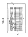
- FIG. 3 shows a state of the squares 2 with numerals "0 - 9" entered therein and the first squares 4 to the sixth squares 9 of the columns 3 with bar patterns 10 drawn therein, each of which is defined so as to univocally represent the corresponding numeral.
- the numeral "0” is indicated by drawing a bar pattern 10 all the way from the first square 4 to the sixth square 9 in the longitudinal direction of the column 3
- the numeral "5" is indicated by drawing a bar pattern 10 only in the first square 4 in the longitudinal direction
- the numeral "1” is indicated by drawing a bar pattern 10 only in the second square 5
- the numeral "2” is indicated by linearly drawing a bar pattern 10 in the second square 5 and the third square 6, and the same rule is applied to the following until the numeral "4" is indicated by linearly drawing a bar pattern 10 all the way from the second square 5 to the fifth square 8.
- the numeral "6" is indicated by linearly drawing a bar pattern 10 in the first square 4 and the second square 5, and the same rule is applied to the following until the numeral "9” is indicated by linearly drawing a bar pattern 10 all way from the first square 4 to the fifth square 8.
- the squares 2 and the columns 3 are provided as the guides for entering the numerals and bar patterns 10 therein, which may also be given by squares in some color to which a later discussed scanning device of an optical reading apparatus is not sensitive.
- a one-digit numeral is represented by a pair of the square 2 and the column 3 and a two-digit numeral is represented by two pairs of the squares 2 and the columns 3 arranged somewhat close to each other in the horizontal direction.
- a numeral consisting of more digits can be represented by additionally arranging one pair of the square 2 and the column 3 closely to the original pairs for each increase of the digit.
- a 14-digit numeral is shown in the example of FIG. 3.
- the person who writes out the slip will enter one out of the numerals 0 - 9 in the squares 2 according to the need and draw bar patterns 10 as defined in the foregoing in the columns 3 corresponding to the entered numerals.
- FIG. 4 is a block diagram showing an overall arrangement of an automatic input apparatus of the slip, wherein reference numeral 11 denotes a facsimile unit as a scanning device, 12 denotes an adapter operating as a substitute for the facsimile unit, and 13 denotes a central processing unit (CPU).
- reference numeral 11 denotes a facsimile unit as a scanning device
- 12 denotes an adapter operating as a substitute for the facsimile unit
- 13 denotes a central processing unit (CPU).
- CPU central processing unit
- the facsimile unit 11 and the adapter 12 are capable of communicating with a remote facsimile unit through a public line or facsimile (F) line.
- a remote facsimile unit through a public line or facsimile (F) line.
- Such an apparatus scans and converts photoelectrically the marks 20 - 23 etc. delineated on a sheet 1.
- Reference numeral 14 denotes a buffer memory
- 15 denotes a random access memory (RAM)
- 16 17 denote read only memories (ROMs)
- 18 denotes a file unit
- 27 denotes a binary numeral reading unit.
- the image data generated by the facsimile unit 11 are supplied to the buffer memory 14.
- the image data are processed by the CPU 13 on the RAM 15 as a work memory together with data from the ROMs 16, 17, file unit 18, and the binary numeral reading unit 27, and interim result and final result are temporarily stored in the RAM 15.
- the final result of the processing is adapted to be delivered converted to a numerical code through the CPU 13 to a host computer or other data processor.
- the ROM 16 stores therein in advance the numerals 0 - 9 and the criterion bar patterns univocally corresponding thereto as defined above, whereas the ROM 17 stores therein in advance criterion numeral patterns 0 - 9 as image data on, for example, a 5 x 7 dot matrix.
- These ROMs 16, 17 are used for recognizing or decoding the frame information marks 23 - 25.
- the binary numeral reading unit 27 is a device for calculating a binary numeral by comparing the lengths of the segments of the information mark 20 - 22 in sequence of the arrangement.
- the file unit 18 is constituted of large-capacity magnetic disks or the like, in which formats of various slips to be specified by the classification mark 20, such as formats of transfer slip, refund slip, remittance slip, tax payment slip, and so on, are stored previously.
- the transfer slip for use of the company BBBB is selected and the bank account number, date, and the amount are entered therein in the form of the above described numerals and bar patterns.
- the sheet 1 of the transfer slip finished with the entry is subjected to scanning by the facsimile unit 11, whereby the classification mark 20 and others are photoelectrically converted into image data to be stored in the main buffer memory 14. Otherwise, the sheet 1 is scanned by a facsimile unit located remotely in the company BBBB, whereby data are transmitted to the company AAAA and are put in the main buffer memory 14 through the adapter 12.
- the CPU 13 first separates the classification mark 20 stored in the first storage area from the buffer memory 14 and transfer the same to the RAM 15 so that the data is decoded therein.
- the CPU 13 first measures the length of the first segment a, and then measures the lengths of the segments b - e in succession and stores the data in the RAM 15.
- the CPU 13 relatively compares the lengths of the segments a - e between adjoining segments, i.e., a and b, b and c, ... , in succession.
- a result as indicated in FIG. 5A is obtained.
- the CPU 13 decodes the classification mark 20 into a binary numeral 1011.
- the CPU 13 sets up a storage area with the binary numeral 1011 used as its head.
- the CPU 13 compares the lengths of the segments drawn in succession constituting the information marks 21 to 22, and therefrom, binary numerals 1010 and 0110 are decoded, respectively.
- FIG. 5B shows the process of binary decoding of the mark 21 for the addressee
- FIG. 5C indicates the process of binary decoding of the mark 22 for the sender, respectively.
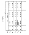
- the CPU 13 searches through the file unit 18 with the binary numeral 1011 of the classification mark 20 used as a guide and retrieves the data list collected therein under the head of the code 1011 as shown in FIG. 7.
- the data list is a format of the transfer slip, from which data in the columns or boxes for the addressee and the sender as well as criterion coordinates (X1, Y1), (X2, Y2), ... , (X5, Y5) of the positions where entries in the boxes for the addressee, sender, amount, bank account No., and the date are to be started, corresponding to the information marks 21 - 25, can be read out.
- the CPU 13 determines whether or not the read out coordinates (x1, y1), (x2, y2), ... , (x5, y5) of the information marks 21 - 25 are in agreement with the predetermined coordinates (X1, Y1), (X2, Y2), ... , (X5, Y5).
- the CPU 13 makes comparisons to determine whether or not the read out coordinates (RAM data) of the information marks 21 - 25 are in agreement with the predetermined coordinates from the file unit 18, and also, whether or not the binary numerals (RAM data) read out from the marks 21 to 22 are in agreement with the criterion binary numerals from the file 18.
- the CPU 13 judges that something abnormal has occurred in the scanning of the sheet 1, for example, after scanning of the mark 20 was made, and rejects the following data, because it is considered that some error has occurred in the course of the data transfer from the facsimile unit 11 and therefore the data are not accurate.
- I1 - I5 are in the same direction and virtually of the same length and m1 - m5 are in the same direction and virtually of the same length, the following data are accepted on the assumption that some skipping has been made in the scanning of the sheet 1 by the facsimile unit 11 after the classification mark 20 was read but there has not occurred anything abnormal after the mark 21 was read. If I1 - I5 and m1 - m5 are close to zero, the data transfer is judged to have been normal.
- the CPU 13 takes the read out image data, if the extracted binary numeral and the criterion value 1010 from the file unit 18 are equal to each other, as that addressed to the company of itself (company AAAA) and accepts the transmitted data.
- the binary numeral extracted from the information mark 22 for the sender is equal to the criterion value 0110, it recognizes the sender as company BBBB, its business acquaintance.
- the CPU 13 After making acknowledgment of the transfer slip, the CPU 13 turns to recognition of the written data in the frame information marks 23 - 25.
- the CPU 13 separates a piece of numeral image data in the square 2 and a piece of bar pattern image data in the column 3 for each digit from the image data for the frame information marks 23 - 25 in the buffer memory 14.
- the numeral image data is compared with criterion numeric patterns from the recognition dictionary in the ROM 17, and a certain recognized candidate numerals arranged in the order of degree of resemblance as well as their degrees of resemblance (%) are calculated to be temporarily stored in the RAM 15.
- the CPU 13 may select "1" as the first candidate numeral with a degree of resemblance of 70% and select "7" as the second candidate numeral with a degree of resemblance of 30%, and store these data temporarily in the RAM 15.
- the corresponding bar pattern image data is compared with a criterion bar patterns from the ROM 16 as the pattern dictionary.
- patterns of high degrees of resemblance are selected and, from the corresponding numerals, the recognized candidate numerals and the degrees of resemblance (%) are calculated and stored temporarily in the RAM 15. Since the bar pattern 10 is subjected to the comparison only for its length, recognition of its corresponding numeral is considerably easy.
- the combination of the numeral "1" and its criterion pattern is selected with a degree of resemblance of 100% and the first candidate numeral "1" and the degree of resemblance 100% are temporarily stored in the RAM 15.
- the candidate numeral "1" in the square 2 and its degree of resemblance 70% are first read out from the RAM 15 and the candidate numeral "1" in the column 3 and its degree of resemblance "100%” are read out to be compared with each other.
- the next candidate numeral "7" in the square 2 and its degree of resemblance 30% and the next candidate numeral in the column 3, or a "NULL" signal because there is no candidate numeral in the present case, are read out and compared with each other.
- the CPU 13 recognizes and outputs the numeral, of which the candidate numerals agree with each other and sum of the degrees of the resemblance thereof gives the maximum value, as the numeral written in the information mark 23. Namely, from the degree 100% of the first candidate "1", the numeral "1" is selected and its code signal (0001) is output to the computer side.
- the numerals of the data entered in the amount box of the information mark 23, the bank account number box of the information mark 24, and the date box of the information mark 25 are recognized and output to the subsequent computer side.
- the kind of the slip is acknowledged by the CPU 13 from the classification mark 20 in the input sheet for the slip.
- the information marks 21 - 22 it is determined whether the slip is addressed to the company of itself (Company AAAA) and it is from its business acquaintance company BBBB. Further, the numerals of data written in the frame information marks 23 - 25 are recognized, and thereby, necessary data on the slip are read out and delivered to the computer side.
- the segment a was, at first, compared with the segment b in length, followed by the comparison between the segments b and c and so on, the first segment a may be compared with the preceding imaginary 0 so that the first bit will always become 1 because 0 ⁇ 1, and such a 1 may be used for error checking.
- the code is not limited to that of binary numerals but may be of other number system with any number used as the base.
- unit patterns of different sizes are not limited to line segments but they may be such patterns as triangles, squares, circles, and bands.
- a facsimile unit as a scanning device and transmitting image data through a public line from a remote branch to a data center in the head office or the like, it is made possible to input accurate data directly to a data processor, without requiring any assistance of human power. Similar data transfer from a facsimile unit in the same site (in the same office) is also possible.
Landscapes
- Physics & Mathematics (AREA)
- Engineering & Computer Science (AREA)
- General Physics & Mathematics (AREA)
- Theoretical Computer Science (AREA)
- Health & Medical Sciences (AREA)
- Electromagnetism (AREA)
- General Health & Medical Sciences (AREA)
- Toxicology (AREA)
- Artificial Intelligence (AREA)
- Computer Vision & Pattern Recognition (AREA)
- Character Discrimination (AREA)
- Character Input (AREA)
Applications Claiming Priority (6)
| Application Number | Priority Date | Filing Date | Title |
|---|---|---|---|
| JP62093123A JPH0814838B2 (ja) | 1987-04-17 | 1987-04-17 | 2進数の表示方法とその読取り装置 |
| JP93123/87 | 1987-04-17 | ||
| JP62104822A JPS63271674A (ja) | 1987-04-30 | 1987-04-30 | 文書の自動入力方法とその装置 |
| JP104822/87 | 1987-04-30 | ||
| JP257384/87 | 1987-10-14 | ||
| JP62257384A JPH0792812B2 (ja) | 1987-10-14 | 1987-10-14 | 伝票とその伝票の読取り方法 |
Publications (3)
| Publication Number | Publication Date |
|---|---|
| EP0288820A2 true EP0288820A2 (fr) | 1988-11-02 |
| EP0288820A3 EP0288820A3 (en) | 1990-06-06 |
| EP0288820B1 EP0288820B1 (fr) | 1994-07-20 |
Family
ID=27307222
Family Applications (1)
| Application Number | Title | Priority Date | Filing Date |
|---|---|---|---|
| EP88105854A Expired - Lifetime EP0288820B1 (fr) | 1987-04-17 | 1988-04-13 | Fiche, méthode et appareil pour la lecture automatique d'une telle fiche |
Country Status (3)
| Country | Link |
|---|---|
| US (1) | US5059775A (fr) |
| EP (1) | EP0288820B1 (fr) |
| DE (1) | DE3850696T2 (fr) |
Cited By (3)
| Publication number | Priority date | Publication date | Assignee | Title |
|---|---|---|---|---|
| EP0568140A1 (fr) * | 1992-04-27 | 1993-11-03 | Koninklijke Philips Electronics N.V. | Système automatisé de traitement et de génération de formulaires, et formulaire associé à ce système |
| EP0504743A3 (fr) * | 1991-03-19 | 1994-01-05 | T A S & Trading Co Ltd | |
| FR2738650A1 (fr) * | 1995-09-13 | 1997-03-14 | Moussette Jean Pierre Roger De | Procede de reconnaissance par lecture optoelectronique de signes alphanumeriques et symboliques a remplissage manuscrit ou imprime |
Families Citing this family (4)
| Publication number | Priority date | Publication date | Assignee | Title |
|---|---|---|---|---|
| US5247591A (en) * | 1990-10-10 | 1993-09-21 | Interfax, Inc. | Method and apparatus for the primary and secondary routing of fax mesages using hand printed characters |
| US5340966A (en) * | 1990-10-23 | 1994-08-23 | Matsushita Electric Industrial Co., Ltd. | Automatic facsimile-receiving-sheet recognizing apparatus |
| DE4407602C2 (de) * | 1994-03-08 | 1997-06-26 | Ferrari Electronic Gmbh | Verfahren zur Auswertung von Markierungsbogen |
| US6834853B2 (en) * | 2002-11-18 | 2004-12-28 | Hewlett-Packard Development Company, Lp | Multi-pass deskew method and apparatus |
Citations (2)
| Publication number | Priority date | Publication date | Assignee | Title |
|---|---|---|---|---|
| JPS5326945A (en) | 1976-08-24 | 1978-03-13 | Mitsubishi Electric Corp | Time division processing digital protective relay |
| EP0103788A2 (fr) | 1982-09-17 | 1984-03-28 | International Business Machines Corporation | Méthode et appareil pour lire des feuilles marquées |
Family Cites Families (7)
| Publication number | Priority date | Publication date | Assignee | Title |
|---|---|---|---|---|
| US3632995A (en) * | 1968-05-09 | 1972-01-04 | Howard W Wilson | Coded article |
| CA1059632A (fr) * | 1971-01-08 | 1979-07-31 | Bruce W. Dobras | Methode et systeme d'interpretation d'enregistrements codes |
| DE3062991D1 (en) * | 1979-01-02 | 1983-06-16 | Westinghouse Electric Corp | Optical mark reading system |
| US4408121A (en) * | 1982-02-09 | 1983-10-04 | International Business Machines Corporation | Code format for bank check identification |
| US4430563A (en) * | 1982-04-30 | 1984-02-07 | Minnesota Mining And Manufacturing Company | Data processing form |
| IL78437A0 (en) * | 1986-04-08 | 1986-08-31 | Tiferet Fashion Accessories 85 | Promissory note |
| US4736109A (en) * | 1986-08-13 | 1988-04-05 | Bally Manufacturing Company | Coded document and document reading system |
-
1988
- 1988-04-01 US US07/177,595 patent/US5059775A/en not_active Expired - Fee Related
- 1988-04-13 DE DE3850696T patent/DE3850696T2/de not_active Expired - Fee Related
- 1988-04-13 EP EP88105854A patent/EP0288820B1/fr not_active Expired - Lifetime
Patent Citations (2)
| Publication number | Priority date | Publication date | Assignee | Title |
|---|---|---|---|---|
| JPS5326945A (en) | 1976-08-24 | 1978-03-13 | Mitsubishi Electric Corp | Time division processing digital protective relay |
| EP0103788A2 (fr) | 1982-09-17 | 1984-03-28 | International Business Machines Corporation | Méthode et appareil pour lire des feuilles marquées |
Cited By (4)
| Publication number | Priority date | Publication date | Assignee | Title |
|---|---|---|---|---|
| EP0504743A3 (fr) * | 1991-03-19 | 1994-01-05 | T A S & Trading Co Ltd | |
| EP0568140A1 (fr) * | 1992-04-27 | 1993-11-03 | Koninklijke Philips Electronics N.V. | Système automatisé de traitement et de génération de formulaires, et formulaire associé à ce système |
| FR2738650A1 (fr) * | 1995-09-13 | 1997-03-14 | Moussette Jean Pierre Roger De | Procede de reconnaissance par lecture optoelectronique de signes alphanumeriques et symboliques a remplissage manuscrit ou imprime |
| WO1997010565A1 (fr) * | 1995-09-13 | 1997-03-20 | Moussette Jean Pierre | Dispositif de signes et procede de lecture optique |
Also Published As
| Publication number | Publication date |
|---|---|
| EP0288820A3 (en) | 1990-06-06 |
| DE3850696D1 (de) | 1994-08-25 |
| US5059775A (en) | 1991-10-22 |
| EP0288820B1 (fr) | 1994-07-20 |
| DE3850696T2 (de) | 1995-03-09 |
Similar Documents
| Publication | Publication Date | Title |
|---|---|---|
| US5434932A (en) | Line alignment apparatus and process | |
| AU769381B2 (en) | A method and apparatus for processing documents in an image-based document processing system | |
| US5280544A (en) | Optical character reading apparatus and method | |
| EP0063454A2 (fr) | Méthode pour la reconnaissance de caractères codés par machine | |
| US4608489A (en) | Method and apparatus for dynamically segmenting a bar code | |
| US4590606A (en) | Multi-function image processing system | |
| US4087788A (en) | Data compression system | |
| JP3088019B2 (ja) | 媒体処理装置及び媒体処理方法 | |
| EP0125877B1 (fr) | Appareil d'entrée d'information | |
| US7305131B2 (en) | Extracting graphical bar codes from an input image | |
| JPS6077279A (ja) | 文字イメ−ジ切出し方法 | |
| US5059775A (en) | Slip and method of and apparatus for automatic reading of the slip | |
| EP0144006B1 (fr) | Procédé et dispositif pour la reconnaissance de caractères | |
| EP0651337A1 (fr) | Procede et appareil de reconnaissance d'objets, et procede et appareil de traitement d'images | |
| JP3448895B2 (ja) | 取引処理装置 | |
| JPS5841542B2 (ja) | 光学式文字読取装置 | |
| JPH05108689A (ja) | 為替振込処理装置 | |
| JPH04268685A (ja) | 帳票類の種類判別方法 | |
| JPH07249099A (ja) | 帳票識別装置 | |
| JP4221960B2 (ja) | 帳票識別装置及びその識別方法 | |
| JP3648270B2 (ja) | 帳票類読取装置及び会計帳票読取装置 | |
| JP2722434B2 (ja) | 光学文字読取装置 | |
| JPH0619884A (ja) | 名称入力システム | |
| US6608944B1 (en) | Value based scoring for optical character recognition | |
| JP2784004B2 (ja) | 文字認識装置 |
Legal Events
| Date | Code | Title | Description |
|---|---|---|---|
| PUAI | Public reference made under article 153(3) epc to a published international application that has entered the european phase |
Free format text: ORIGINAL CODE: 0009012 |
|
| AK | Designated contracting states |
Kind code of ref document: A2 Designated state(s): DE FR GB IT |
|
| PUAL | Search report despatched |
Free format text: ORIGINAL CODE: 0009013 |
|
| AK | Designated contracting states |
Kind code of ref document: A3 Designated state(s): DE FR GB IT |
|
| RHK1 | Main classification (correction) |
Ipc: G06K 19/06 |
|
| 17P | Request for examination filed |
Effective date: 19900725 |
|
| 17Q | First examination report despatched |
Effective date: 19920316 |
|
| GRAA | (expected) grant |
Free format text: ORIGINAL CODE: 0009210 |
|
| AK | Designated contracting states |
Kind code of ref document: B1 Designated state(s): DE FR GB IT |
|
| PG25 | Lapsed in a contracting state [announced via postgrant information from national office to epo] |
Ref country code: IT Free format text: LAPSE BECAUSE OF FAILURE TO SUBMIT A TRANSLATION OF THE DESCRIPTION OR TO PAY THE FEE WITHIN THE PRE;WARNING: LAPSES OF ITALIAN PATENTS WITH EFFECTIVE DATE BEFORE 2007 MAY HAVE OCCURRED AT ANY TIME BEFORE 2007. THE CORRECT EFFECTIVE DATE MAY BE DIFFERENT FROM THE ONE RECORDED.SCRIBED TIME-LIMIT Effective date: 19940720 Ref country code: FR Effective date: 19940720 |
|
| REF | Corresponds to: |
Ref document number: 3850696 Country of ref document: DE Date of ref document: 19940825 |
|
| EN | Fr: translation not filed | ||
| PLBE | No opposition filed within time limit |
Free format text: ORIGINAL CODE: 0009261 |
|
| STAA | Information on the status of an ep patent application or granted ep patent |
Free format text: STATUS: NO OPPOSITION FILED WITHIN TIME LIMIT |
|
| 26N | No opposition filed | ||
| PGFP | Annual fee paid to national office [announced via postgrant information from national office to epo] |
Ref country code: GB Payment date: 19960325 Year of fee payment: 9 |
|
| PGFP | Annual fee paid to national office [announced via postgrant information from national office to epo] |
Ref country code: DE Payment date: 19960424 Year of fee payment: 9 |
|
| PG25 | Lapsed in a contracting state [announced via postgrant information from national office to epo] |
Ref country code: GB Effective date: 19970413 |
|
| GBPC | Gb: european patent ceased through non-payment of renewal fee |
Effective date: 19970413 |
|
| PG25 | Lapsed in a contracting state [announced via postgrant information from national office to epo] |
Ref country code: DE Free format text: LAPSE BECAUSE OF NON-PAYMENT OF DUE FEES Effective date: 19980101 |