EP0288821A2 - Dispositif et procédé de liaison permanente des hélices de convoyeurs à vis en matière plastique - Google Patents
Dispositif et procédé de liaison permanente des hélices de convoyeurs à vis en matière plastique Download PDFInfo
- Publication number
- EP0288821A2 EP0288821A2 EP88105862A EP88105862A EP0288821A2 EP 0288821 A2 EP0288821 A2 EP 0288821A2 EP 88105862 A EP88105862 A EP 88105862A EP 88105862 A EP88105862 A EP 88105862A EP 0288821 A2 EP0288821 A2 EP 0288821A2
- Authority
- EP
- European Patent Office
- Prior art keywords
- edges
- confronting
- modules
- edge
- plastic
- Prior art date
- Legal status (The legal status is an assumption and is not a legal conclusion. Google has not performed a legal analysis and makes no representation as to the accuracy of the status listed.)
- Granted
Links
Images


Classifications
-
- B—PERFORMING OPERATIONS; TRANSPORTING
- B29—WORKING OF PLASTICS; WORKING OF SUBSTANCES IN A PLASTIC STATE IN GENERAL
- B29C—SHAPING OR JOINING OF PLASTICS; SHAPING OF MATERIAL IN A PLASTIC STATE, NOT OTHERWISE PROVIDED FOR; AFTER-TREATMENT OF THE SHAPED PRODUCTS, e.g. REPAIRING
- B29C66/00—General aspects of processes or apparatus for joining preformed parts
- B29C66/50—General aspects of joining tubular articles; General aspects of joining long products, i.e. bars or profiled elements; General aspects of joining single elements to tubular articles, hollow articles or bars; General aspects of joining several hollow-preforms to form hollow or tubular articles
- B29C66/51—Joining tubular articles, profiled elements or bars; Joining single elements to tubular articles, hollow articles or bars; Joining several hollow-preforms to form hollow or tubular articles
- B29C66/54—Joining several hollow-preforms, e.g. half-shells, to form hollow articles, e.g. for making balls, containers; Joining several hollow-preforms, e.g. half-cylinders, to form tubular articles
- B29C66/543—Joining several hollow-preforms, e.g. half-shells, to form hollow articles, e.g. for making balls, containers; Joining several hollow-preforms, e.g. half-cylinders, to form tubular articles joining more than two hollow-preforms to form said hollow articles
-
- B—PERFORMING OPERATIONS; TRANSPORTING
- B29—WORKING OF PLASTICS; WORKING OF SUBSTANCES IN A PLASTIC STATE IN GENERAL
- B29C—SHAPING OR JOINING OF PLASTICS; SHAPING OF MATERIAL IN A PLASTIC STATE, NOT OTHERWISE PROVIDED FOR; AFTER-TREATMENT OF THE SHAPED PRODUCTS, e.g. REPAIRING
- B29C45/00—Injection moulding, i.e. forcing the required volume of moulding material through a nozzle into a closed mould; Apparatus therefor
- B29C45/14—Injection moulding, i.e. forcing the required volume of moulding material through a nozzle into a closed mould; Apparatus therefor incorporating preformed parts or layers, e.g. injection moulding around inserts or for coating articles
- B29C45/14467—Joining articles or parts of a single article
-
- B—PERFORMING OPERATIONS; TRANSPORTING
- B29—WORKING OF PLASTICS; WORKING OF SUBSTANCES IN A PLASTIC STATE IN GENERAL
- B29C—SHAPING OR JOINING OF PLASTICS; SHAPING OF MATERIAL IN A PLASTIC STATE, NOT OTHERWISE PROVIDED FOR; AFTER-TREATMENT OF THE SHAPED PRODUCTS, e.g. REPAIRING
- B29C65/00—Joining or sealing of preformed parts, e.g. welding of plastics materials; Apparatus therefor
- B29C65/02—Joining or sealing of preformed parts, e.g. welding of plastics materials; Apparatus therefor by heating, with or without pressure
- B29C65/10—Joining or sealing of preformed parts, e.g. welding of plastics materials; Apparatus therefor by heating, with or without pressure using hot gases (e.g. combustion gases) or flames coming in contact with at least one of the parts to be joined
-
- B—PERFORMING OPERATIONS; TRANSPORTING
- B29—WORKING OF PLASTICS; WORKING OF SUBSTANCES IN A PLASTIC STATE IN GENERAL
- B29C—SHAPING OR JOINING OF PLASTICS; SHAPING OF MATERIAL IN A PLASTIC STATE, NOT OTHERWISE PROVIDED FOR; AFTER-TREATMENT OF THE SHAPED PRODUCTS, e.g. REPAIRING
- B29C65/00—Joining or sealing of preformed parts, e.g. welding of plastics materials; Apparatus therefor
- B29C65/02—Joining or sealing of preformed parts, e.g. welding of plastics materials; Apparatus therefor by heating, with or without pressure
- B29C65/40—Applying molten plastics, e.g. hot melt
- B29C65/42—Applying molten plastics, e.g. hot melt between pre-assembled parts
-
- B—PERFORMING OPERATIONS; TRANSPORTING
- B29—WORKING OF PLASTICS; WORKING OF SUBSTANCES IN A PLASTIC STATE IN GENERAL
- B29C—SHAPING OR JOINING OF PLASTICS; SHAPING OF MATERIAL IN A PLASTIC STATE, NOT OTHERWISE PROVIDED FOR; AFTER-TREATMENT OF THE SHAPED PRODUCTS, e.g. REPAIRING
- B29C65/00—Joining or sealing of preformed parts, e.g. welding of plastics materials; Apparatus therefor
- B29C65/70—Joining or sealing of preformed parts, e.g. welding of plastics materials; Apparatus therefor by moulding
-
- B—PERFORMING OPERATIONS; TRANSPORTING
- B29—WORKING OF PLASTICS; WORKING OF SUBSTANCES IN A PLASTIC STATE IN GENERAL
- B29C—SHAPING OR JOINING OF PLASTICS; SHAPING OF MATERIAL IN A PLASTIC STATE, NOT OTHERWISE PROVIDED FOR; AFTER-TREATMENT OF THE SHAPED PRODUCTS, e.g. REPAIRING
- B29C66/00—General aspects of processes or apparatus for joining preformed parts
- B29C66/01—General aspects dealing with the joint area or with the area to be joined
- B29C66/02—Preparation of the material, in the area to be joined, prior to joining or welding
- B29C66/024—Thermal pre-treatments
- B29C66/0242—Heating, or preheating, e.g. drying
-
- B—PERFORMING OPERATIONS; TRANSPORTING
- B29—WORKING OF PLASTICS; WORKING OF SUBSTANCES IN A PLASTIC STATE IN GENERAL
- B29C—SHAPING OR JOINING OF PLASTICS; SHAPING OF MATERIAL IN A PLASTIC STATE, NOT OTHERWISE PROVIDED FOR; AFTER-TREATMENT OF THE SHAPED PRODUCTS, e.g. REPAIRING
- B29C45/00—Injection moulding, i.e. forcing the required volume of moulding material through a nozzle into a closed mould; Apparatus therefor
- B29C45/14—Injection moulding, i.e. forcing the required volume of moulding material through a nozzle into a closed mould; Apparatus therefor incorporating preformed parts or layers, e.g. injection moulding around inserts or for coating articles
- B29C2045/1486—Details, accessories and auxiliary operations
- B29C2045/14868—Pretreatment of the insert, e.g. etching, cleaning
- B29C2045/14877—Pretreatment of the insert, e.g. etching, cleaning preheating or precooling the insert for non-deforming purposes
-
- B—PERFORMING OPERATIONS; TRANSPORTING
- B29—WORKING OF PLASTICS; WORKING OF SUBSTANCES IN A PLASTIC STATE IN GENERAL
- B29C—SHAPING OR JOINING OF PLASTICS; SHAPING OF MATERIAL IN A PLASTIC STATE, NOT OTHERWISE PROVIDED FOR; AFTER-TREATMENT OF THE SHAPED PRODUCTS, e.g. REPAIRING
- B29C66/00—General aspects of processes or apparatus for joining preformed parts
- B29C66/70—General aspects of processes or apparatus for joining preformed parts characterised by the composition, physical properties or the structure of the material of the parts to be joined; Joining with non-plastics material
- B29C66/71—General aspects of processes or apparatus for joining preformed parts characterised by the composition, physical properties or the structure of the material of the parts to be joined; Joining with non-plastics material characterised by the composition of the plastics material of the parts to be joined
Definitions
- This invention relates to apparatus and methods for permanently joining or bonding the flights of plastic screw conveyor modules and more particularly to such apparatus for joining the confronting flights of such integrally molded plastic screw conveyor modules in a manner suitable for meeting USDA requirements for food processing.
- the edges of confronting flights of adjacent modules are enclosed and clamped in place by the apparatus.
- a hot gas such as nitrogen or air is then injected between the confronting edges of the flights to bring the confronting edges substantially to the melting point of the plastic modules.
- a plastic material is then injected under pressure and temperature between the heated confronting edges of the enclosed flights and allowed to solidify until complete bonding takes place.
- Such conveyors generally include a helical shaped member which rotates within a housing or trough such that rotation of the screw conveyor along its longitudinal or central axis results in movement of the bulk material along the length of the device.
- Such conveyors were typically constructed from metal and each conveyor was specifically designed for a particular purpose and of a particular length.
- each conveyor was specifically designed for a particular purpose and of a particular length.
- one of the advantages of the plastic modular screw conveyor is ease of cleaning due to the smooth and non-interrupted surfaces.
- a screw conveyor of any length can be fabricated.
- any process which fills up spaces between flights must not result in any small cavities or openings which could harbor bacteria.
- the apparatus of the invention comprises a means for supporting a plurality of integrally molded plastic screw conveyor modules in axial alignment, and with an edge of the flight member of one of the modules in confronting relationship with an edge of the flight member of another one of the modules.
- the confronting edges to be bonded are enclosed and maintained in a fixed position with respect to each other by means such as a clamp.
- Gas such as nitrogen is provided at an elevated temperature through a passage in the clamp to the confronting edges of the flight members to heat the edges to substantially the melting temperature of the plastic modules.
- a plastic material is then provided under temperature and pressure through a passage in the clamp enclosing the confronting heated edges of the module to fill and bond an edge of one module to the confronting edge of an adjacent module.
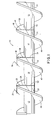
- Fig. 1 there is shown a plan view of a plurality 10 of plastic screw conveyor modules 12, 14, 16 and 18.
- the modules are axially aligned as shown, and although the hub or axial members 20, 22, 24 and 26 of adjacent modules are joined or bonded and in contact with each other, it is clearly seen that gaps or spaces represented by double arrows 28 and 30 exist between the confronting edges 32 and 34, and 36 and 38 respectively of flight members 40, 42 and 44.
- the original space indicated by dotted lines 46 and 48 between confronting edges of flight members 44 and 50 illustrate how the space between confronting edges of flight members is filled thereby joining and bonding the edges according to the methods and apparatus of this invention.
- the USDA requirements can normally be achieved by joining the ends of the axial members or hubs together in a fluid tight manner such that there are no tiny crevices or openings to collect fluids and harbor the growth of bacteria.
- modules 12 and 14 are seen to be clearly bonded together as indicated by seam 52.
- modules 14 and 16 are bonded by seam 54 as are modules 16 and 18 bonded by seam 56.
- the bonding of the hubs or axial members of the modules in a satisfactory manner is all that is necessary to achieve USDA approval.
- sufficient gaps or spaces remain between the confronting edges of flight members such that the gaps or spaces can be readily cleaned and inspected.
- the spaces and gaps indicated by double arrows 28 and 30 illustrate such clearances.
- a flight member which has no discontinuities in the entire length of the flight member from one end to the other.
- the edges of the confronting flight members must be joined or bonded together, and to meet USDA specifications the bond must be completely free of tiny openings or crevices which could collect bacteria and fluids. Therefore, the resulting joint or bond formed by the apparatus and method of the present invention must be a high quality, smooth and fluid-tight bond.
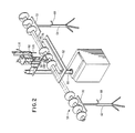
- Figs. 2, 3A and 3B there is shown a perspective view, a plan view and an end view of the apparatus of the present invention which shows a plurality of modules wherein the confronting edges of flight members are being bonded and joined according to the teachings of this invention.
- Figs. 2 and 3A there is a multiplicity of modules of the screw conveyor which have the flight members joined to provide a continuous flight member the entire length of the modules.
- the modules indicated generally as 58 are supported by a three-section support stand or means 60, 62 and 64.
- the center or primary support unit 60 supports the modules presently being bonded, whereas the auxiliary support stands 62 and 64 simply provide support for those modules already having their flights joined or those modules which will have their flights joined.
- support stands 62 and 64 may readily have their height adjusted by means of adjusting screws 66 and 68 respectively.
- the support stands 62 and 64 include a table portion 70 and 72 each of which may hold a pair of parallel support rails 74 and 76 as shown in Fig. 3A (not shown in Fig. 2). These support rails receive and support the flight members of the joined screw conveyor.
- the main support means 60 also includes a pair of support rails 78 and 80.
- table 82 which carry support rails 78 and 80 may readily be adjusted by means of a crank 84 and rack and gear arrangement indicated by reference number 86.
- the rails 78 and 80 support the plurality of modular screw conveyors 58 such that centerline 88 of the plurality of screw conveyor 58 is aligned with the heating-head 90 and injection-head 92 to be discussed in detail hereinafter.
- Fig. 4 shows flight members 94 and 96 of two axially joined modules as indicated by bead 95. Although blocked from view in the Fig. 4, there will be a gap between the confronting edges of flight members 94 and 96 such as the gaps indicated in Fig. 1 by double arrows 28 and 30. Also as shown there is an enclosing clamp means 98 comprised of two sections 100 and 102 which fit on each side of the two confronting flight members. Enclosing clamp 98 will have a pair of surfaces which will conform to the two parallel helical surfaces of the flight members. For ease of illustration, the enclosing clamp member 98 is shown being held tightly in position by means of a manual C-clamp 104.
- clamping means 98 extends from the hub 106 of the modules to be joined out beyond the edge 108. Also as will be appreciated, the edges of the clamp fit snugly against the plastic flight members to provide substantially a fluid-tight enclosure.
- opening 112. At the top portion 110 of enclosing clamp 98, there is shown an opening 112. As will be appreciated and discussed hereinafter, opening 112 allows hot gases to be provided to the confronting edges of the flight members to be joined and also allows the injection of melted plastic under high temperatures and pressures.
- heating-head 90 includes a source of gas such as nitrogen heated to elevated temperatures on the order of 550°F and provided through tube 118.
- Heating-head 90 also includes a substantially tubular member 120 which has a cross-section substantially equal and conforming to the cross-section of the space between the two confronting edges of the flight members being joined.
- tubular member 120 includes a plurality of apertures or holes such as aperture 122, 124 and 126 such that hot air forced into tube 120 will leave through the apertures.
- aperture 122, 124 and 126 such that hot air forced into tube 120 will leave through the apertures.
- the injection tube 120 is then removed and the pair of modules 114 and 116 to be joined are moved directly below the injection-head 92. Injection-head 92 is lowered such that nozzle 128 is in contact with the opening 112.
- An appropriate plastic which will be compatible to the plastic of the modules 114 and 116 is then injection under high temperatures and pressures as a liquid form into the space between the two confronting edges of the flight members so as to completely fill the space.
- the injection pressure and temperature for bonding polypropylene, polyethylene and polyurethane are 60 PSI at 450°F for polypropylene, 60 PSI at 375°F for polyethylene, and 60 PSI at 400°F for polyurethane.
- the nozzle 128 is then raised from the opening 112 and the modules 114 and 116 moved out of the way to cool and make ready for the filling and bonding of the next set of flight members.
- the clamp is then removed leaving the flight members filled and bonded with a smooth joint which meets USDA specifications and requirements.
Landscapes
- Engineering & Computer Science (AREA)
- Mechanical Engineering (AREA)
- Physics & Mathematics (AREA)
- Thermal Sciences (AREA)
- Chemical & Material Sciences (AREA)
- Combustion & Propulsion (AREA)
- Manufacturing & Machinery (AREA)
- Lining Or Joining Of Plastics Or The Like (AREA)
Applications Claiming Priority (2)
| Application Number | Priority Date | Filing Date | Title |
|---|---|---|---|
| US07/039,697 US4746384A (en) | 1987-04-20 | 1987-04-20 | Apparatus and method for permanently joining plastic screw conveyor flights |
| US39697 | 1987-04-20 |
Publications (3)
| Publication Number | Publication Date |
|---|---|
| EP0288821A2 true EP0288821A2 (fr) | 1988-11-02 |
| EP0288821A3 EP0288821A3 (fr) | 1991-07-31 |
| EP0288821B1 EP0288821B1 (fr) | 1994-09-21 |
Family
ID=21906896
Family Applications (1)
| Application Number | Title | Priority Date | Filing Date |
|---|---|---|---|
| EP88105862A Expired - Lifetime EP0288821B1 (fr) | 1987-04-20 | 1988-04-13 | Dispositif et procédé de liaison permanente des hélices de convoyeurs à vis en matière plastique |
Country Status (4)
| Country | Link |
|---|---|
| US (1) | US4746384A (fr) |
| EP (1) | EP0288821B1 (fr) |
| CA (1) | CA1313445C (fr) |
| DE (1) | DE3851567T2 (fr) |
Cited By (2)
| Publication number | Priority date | Publication date | Assignee | Title |
|---|---|---|---|---|
| WO1999029491A1 (fr) * | 1997-12-09 | 1999-06-17 | Henkel Kommanditgessellschaft Auf Aktien | Procede pour coller des objets en plastique a l'aide d'une colle a fusion |
| FR2833511A1 (fr) * | 2001-12-18 | 2003-06-20 | Denso Corp | Procede pour assembler des produits a base de resine par chauffage des surfaces de jonction |
Families Citing this family (9)
| Publication number | Priority date | Publication date | Assignee | Title |
|---|---|---|---|---|
| US5099985A (en) * | 1983-09-29 | 1992-03-31 | The Laitram Corporation | Unitary screw conveyor apparatus |
| US4913280A (en) * | 1988-12-20 | 1990-04-03 | Du Pont Canada Inc. | Auger for particulate materials |
| US5899319A (en) * | 1996-10-09 | 1999-05-04 | Farmers Rice Milling Company, Inc. | Coupling and process for screw conveyors |
| SE0102452L (sv) * | 2001-07-05 | 2003-01-06 | Core Link Ab | Sätt och anordning för skarvning |
| USD475372S1 (en) | 2002-05-02 | 2003-06-03 | Derron D. Dulkoski | Auger assembly |
| JP4023465B2 (ja) * | 2004-03-25 | 2007-12-19 | 株式会社デンソー | 樹脂成形品の二次成形時における加熱媒体送給方法及び装置 |
| USD943650S1 (en) * | 2021-02-05 | 2022-02-15 | Xinwei Li | Auger drill bit |
| USD944301S1 (en) * | 2021-02-07 | 2022-02-22 | Jun Li | Auger drill bit |
| USD942517S1 (en) * | 2021-02-07 | 2022-02-01 | Jun Li | Auger drill bit |
Family Cites Families (9)
| Publication number | Priority date | Publication date | Assignee | Title |
|---|---|---|---|---|
| US2815852A (en) * | 1953-08-17 | 1957-12-10 | Allis Chalmers Mfg Co | Auger conveyer extension |
| GB1128878A (en) * | 1967-06-02 | 1968-10-02 | Standard Telephones Cables Ltd | Moulded cable sheath joint |
| US3705644A (en) * | 1970-01-23 | 1972-12-12 | Claude Edward Kawchitch | Conveyor screw element |
| US3664444A (en) * | 1970-05-11 | 1972-05-23 | Mobile Drilling Co Inc | Air drilling method using controlled split stream |
| US3839126A (en) * | 1972-07-03 | 1974-10-01 | Dow Chemical Co | Plastic welding apparatus |
| JPS57140119A (en) * | 1981-02-26 | 1982-08-30 | Aisin Seiki Co Ltd | Nozzle of hot-air welder for bonding different resin members |
| FR2519579A1 (fr) * | 1982-01-14 | 1983-07-18 | Commissariat Energie Atomique | Procede de fabrication des plaques d'un echangeur de chaleur, par assemblage d'elements bout a bout, en matiere plastique |
| JPS59157374A (ja) * | 1982-12-30 | 1984-09-06 | オ−リユウス・リミテツド | 布様材料の処理方法 |
| US4691818A (en) * | 1986-01-27 | 1987-09-08 | The Laitram Corp. | Concealed drive coupling for use with modular screw conveyor |
-
1987
- 1987-04-20 US US07/039,697 patent/US4746384A/en not_active Expired - Lifetime
-
1988
- 1988-04-05 CA CA000563287A patent/CA1313445C/fr not_active Expired - Fee Related
- 1988-04-13 DE DE3851567T patent/DE3851567T2/de not_active Expired - Fee Related
- 1988-04-13 EP EP88105862A patent/EP0288821B1/fr not_active Expired - Lifetime
Cited By (3)
| Publication number | Priority date | Publication date | Assignee | Title |
|---|---|---|---|---|
| WO1999029491A1 (fr) * | 1997-12-09 | 1999-06-17 | Henkel Kommanditgessellschaft Auf Aktien | Procede pour coller des objets en plastique a l'aide d'une colle a fusion |
| US6627036B1 (en) | 1997-12-09 | 2003-09-30 | Henkel Kommanditgesellschaft Auf Aktien | Method for gluing plastic objects with a hot-melt adhesive |
| FR2833511A1 (fr) * | 2001-12-18 | 2003-06-20 | Denso Corp | Procede pour assembler des produits a base de resine par chauffage des surfaces de jonction |
Also Published As
| Publication number | Publication date |
|---|---|
| US4746384A (en) | 1988-05-24 |
| DE3851567T2 (de) | 1995-04-27 |
| CA1313445C (fr) | 1993-02-09 |
| DE3851567D1 (de) | 1994-10-27 |
| EP0288821A3 (fr) | 1991-07-31 |
| EP0288821B1 (fr) | 1994-09-21 |
Similar Documents
| Publication | Publication Date | Title |
|---|---|---|
| US4746384A (en) | Apparatus and method for permanently joining plastic screw conveyor flights | |
| US4030540A (en) | Tube nest for heat exchangers, and modular elements for said nest consisting of thermoplastic tubes, and process for manufacturing the modular elements and the tube nests | |
| US4832773A (en) | Techniques for welding thermoplastic tubes | |
| EP0471953A2 (fr) | Procédé de confinement total des entrées et des sorties stériles pour des systèmes fermés utilisant des tubes plastiques | |
| JP3418395B2 (ja) | 超音波溶接プラスチック・リボンならびにこれを形成する装置及び方法 | |
| US8918980B2 (en) | Beverage bottle handling machine construction method | |
| JP4820378B2 (ja) | 前テーブルシステム | |
| US9284841B1 (en) | Disposable heat exchanger assembly for sterile and aseptic biotechnology and pharmaceutical manufacturing applications | |
| US5676778A (en) | Method of manufacturing a filter assembly and the filter assembly produced thereby | |
| JPH01167028A (ja) | 包装機械中の無菌および非無菌環境を隔離するための手段 | |
| DE69928025T2 (de) | Vorrichtung zum schweissen ohne erzeugung von wülsten | |
| CN221418704U (zh) | 一种预灌封装置 | |
| US12111002B1 (en) | Fluid distribution junctions and assembly methods | |
| CN217776095U (zh) | 管道管台焊接用防变形工装 | |
| JPH08236A (ja) | 食品殺菌法 | |
| US3936345A (en) | Apparatus for welding flexible members into a frame | |
| JPH05345357A (ja) | プラスチック部品の接合方法 | |
| EP1499843A1 (fr) | Dispositif et procede destines a ebarber et a fixer des tuyaux souples a l'interieur d'une structure et articles fabriques a partir de ceux-ci | |
| GB2232370A (en) | Heat exchanger and method of manufacturing | |
| JPS63295313A (ja) | 単体ねじコンベア装置 | |
| CN117485640B (zh) | 一种预灌封装置及方法 | |
| CN221678079U (zh) | 一种管道拼接调节装置 | |
| FI74791C (fi) | Foerfarande foer hopfogning av i olika vinklar foerbundna isolerade roer. | |
| CN223507711U (zh) | 一种输液管装配设备 | |
| EP0015897B1 (fr) | Procede de connexion de tubes avec une piece de connexion et piece de connexion pour la mise en oeuvre du procede |
Legal Events
| Date | Code | Title | Description |
|---|---|---|---|
| PUAI | Public reference made under article 153(3) epc to a published international application that has entered the european phase |
Free format text: ORIGINAL CODE: 0009012 |
|
| AK | Designated contracting states |
Kind code of ref document: A2 Designated state(s): DE FR GB IT |
|
| PUAL | Search report despatched |
Free format text: ORIGINAL CODE: 0009013 |
|
| AK | Designated contracting states |
Kind code of ref document: A3 Designated state(s): DE FR GB IT |
|
| 17P | Request for examination filed |
Effective date: 19911127 |
|
| 17Q | First examination report despatched |
Effective date: 19930128 |
|
| GRAA | (expected) grant |
Free format text: ORIGINAL CODE: 0009210 |
|
| AK | Designated contracting states |
Kind code of ref document: B1 Designated state(s): DE FR GB IT |
|
| REF | Corresponds to: |
Ref document number: 3851567 Country of ref document: DE Date of ref document: 19941027 |
|
| ITF | It: translation for a ep patent filed | ||
| ET | Fr: translation filed | ||
| PLBE | No opposition filed within time limit |
Free format text: ORIGINAL CODE: 0009261 |
|
| STAA | Information on the status of an ep patent application or granted ep patent |
Free format text: STATUS: NO OPPOSITION FILED WITHIN TIME LIMIT |
|
| 26N | No opposition filed | ||
| ITPR | It: changes in ownership of a european patent |
Owner name: CESSIONE;MARTIN SPROCKET & GEAR INC. |
|
| REG | Reference to a national code |
Ref country code: FR Ref legal event code: TP |
|
| REG | Reference to a national code |
Ref country code: GB Ref legal event code: 732E |
|
| PG25 | Lapsed in a contracting state [announced via postgrant information from national office to epo] |
Ref country code: FR Free format text: LAPSE BECAUSE OF NON-PAYMENT OF DUE FEES Effective date: 20011231 |
|
| REG | Reference to a national code |
Ref country code: GB Ref legal event code: IF02 |
|
| REG | Reference to a national code |
Ref country code: FR Ref legal event code: ST |
|
| REG | Reference to a national code |
Ref country code: FR Ref legal event code: RN |
|
| REG | Reference to a national code |
Ref country code: FR Ref legal event code: RN Ref country code: FR Ref legal event code: D3 |
|
| PGFP | Annual fee paid to national office [announced via postgrant information from national office to epo] |
Ref country code: GB Payment date: 20040331 Year of fee payment: 17 |
|
| PGFP | Annual fee paid to national office [announced via postgrant information from national office to epo] |
Ref country code: DE Payment date: 20040408 Year of fee payment: 17 |
|
| PGFP | Annual fee paid to national office [announced via postgrant information from national office to epo] |
Ref country code: FR Payment date: 20040415 Year of fee payment: 17 |
|
| PG25 | Lapsed in a contracting state [announced via postgrant information from national office to epo] |
Ref country code: IT Free format text: LAPSE BECAUSE OF NON-PAYMENT OF DUE FEES;WARNING: LAPSES OF ITALIAN PATENTS WITH EFFECTIVE DATE BEFORE 2007 MAY HAVE OCCURRED AT ANY TIME BEFORE 2007. THE CORRECT EFFECTIVE DATE MAY BE DIFFERENT FROM THE ONE RECORDED. Effective date: 20050413 Ref country code: GB Free format text: LAPSE BECAUSE OF NON-PAYMENT OF DUE FEES Effective date: 20050413 |
|
| PG25 | Lapsed in a contracting state [announced via postgrant information from national office to epo] |
Ref country code: DE Free format text: LAPSE BECAUSE OF NON-PAYMENT OF DUE FEES Effective date: 20051101 |
|
| GBPC | Gb: european patent ceased through non-payment of renewal fee |
Effective date: 20050413 |
|
| REG | Reference to a national code |
Ref country code: FR Ref legal event code: ST Effective date: 20051230 |