EP0288859A1 - Verriegelungsvorrichtung eines Gehäuses mit elektronischen Geräten auf einem Gestell - Google Patents
Verriegelungsvorrichtung eines Gehäuses mit elektronischen Geräten auf einem Gestell Download PDFInfo
- Publication number
- EP0288859A1 EP0288859A1 EP19880106140 EP88106140A EP0288859A1 EP 0288859 A1 EP0288859 A1 EP 0288859A1 EP 19880106140 EP19880106140 EP 19880106140 EP 88106140 A EP88106140 A EP 88106140A EP 0288859 A1 EP0288859 A1 EP 0288859A1
- Authority
- EP
- European Patent Office
- Prior art keywords
- housing
- axis
- locking device
- box
- light
- Prior art date
- Legal status (The legal status is an assumption and is not a legal conclusion. Google has not performed a legal analysis and makes no representation as to the accuracy of the status listed.)
- Granted
Links
Images
Classifications
-
- H—ELECTRICITY
- H05—ELECTRIC TECHNIQUES NOT OTHERWISE PROVIDED FOR
- H05K—PRINTED CIRCUITS; CASINGS OR CONSTRUCTIONAL DETAILS OF ELECTRIC APPARATUS; MANUFACTURE OF ASSEMBLAGES OF ELECTRICAL COMPONENTS
- H05K7/00—Constructional details common to different types of electric apparatus
- H05K7/14—Mounting supporting structure in casing or on frame or rack
- H05K7/1401—Mounting supporting structure in casing or on frame or rack comprising clamping or extracting means
- H05K7/1411—Mounting supporting structure in casing or on frame or rack comprising clamping or extracting means for securing or extracting box-type drawers
- H05K7/1412—Mounting supporting structure in casing or on frame or rack comprising clamping or extracting means for securing or extracting box-type drawers hold down mechanisms, e.g. avionic racks
-
- Y—GENERAL TAGGING OF NEW TECHNOLOGICAL DEVELOPMENTS; GENERAL TAGGING OF CROSS-SECTIONAL TECHNOLOGIES SPANNING OVER SEVERAL SECTIONS OF THE IPC; TECHNICAL SUBJECTS COVERED BY FORMER USPC CROSS-REFERENCE ART COLLECTIONS [XRACs] AND DIGESTS
- Y10—TECHNICAL SUBJECTS COVERED BY FORMER USPC
- Y10T—TECHNICAL SUBJECTS COVERED BY FORMER US CLASSIFICATION
- Y10T292/00—Closure fasteners
- Y10T292/08—Bolts
- Y10T292/0911—Hooked end
- Y10T292/0913—Sliding and swinging
- Y10T292/0914—Operating means
- Y10T292/092—Screw
-
- Y—GENERAL TAGGING OF NEW TECHNOLOGICAL DEVELOPMENTS; GENERAL TAGGING OF CROSS-SECTIONAL TECHNOLOGIES SPANNING OVER SEVERAL SECTIONS OF THE IPC; TECHNICAL SUBJECTS COVERED BY FORMER USPC CROSS-REFERENCE ART COLLECTIONS [XRACs] AND DIGESTS
- Y10—TECHNICAL SUBJECTS COVERED BY FORMER USPC
- Y10T—TECHNICAL SUBJECTS COVERED BY FORMER US CLASSIFICATION
- Y10T74/00—Machine element or mechanism
- Y10T74/18—Mechanical movements
- Y10T74/18568—Reciprocating or oscillating to or from alternating rotary
- Y10T74/18576—Reciprocating or oscillating to or from alternating rotary including screw and nut
- Y10T74/18752—Manually driven
Definitions
- the present invention relates to a device for locking an electronic equipment box on a plate, comprising a movable carriage connected to the front face of the box, a threaded axis along which the carriage moves, a yoke housed under the plate and provided with two inclined lights in which a articulation rod moves fixed to an end of the threaded axis and perpendicular thereto.
- These electronic equipment boxes are placed on fixed plates, permanently mounted in a machine, for example, in the cockpit of an airplane. They comprise at their rear part, the female part of a connector comprising multiple needles of small diameter, therefore relatively fragile, which engage in the male part of the connector permanently mounted at the rear of the plate.
- a locking device whose central axis is provided at its end with a hinge rod moving in an inclined light, two extreme positions allowing one to put in place the housing, so insert the connector, at an acute angle ensuring a vertical component which plates the housing on the bottom of the tray, and the other to remove this housing, therefore to extract the connector parallel to the bottom of the tray .
- the present invention aims to ensure total immobilization of the rod, during the establishment or removal of the housing.
- each light comprises, at one or other of its ends, at least one stop notch in which the rod comes to rest. articulation of the threaded axis.
- each light has in its upper part two notches which allow the immobilization of the articulation rod, the axis then being immobilized in a horizontal position when the housing is put in place or removed, and, in its part lower, a notch which ensures the immobilization of the articulation rod, the axis then being immobilized in an inclined position thus ensuring the permanent retention of the housing against the bottom of the plate.
- each light can only have one or two stop notches.
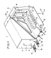
- Figure 1 In Figure 1 are shown two trays, one with a housing and the other not, this to clearly show the constitution of a tray which has a bottom 11 provided with a diaphragm 14 allowing ventilation of the housing , a rear plate 12 on which is mounted the male part 15 of a connector, and finally two lateral flanks 13 perforated and of triangular shape.
- this plate At the front of this plate, and under it, are mounted two yokes 17 each allowing the articulation of an axis 21 of the locking device.
- This device is mechanically connected to a lug 3 of the front face 2 of the housing 1, during the insertion, maintenance and extraction of the housing, the insertion and extraction taking place over a very short distance corresponding approximately the thickness of the rear connector.
- the gripping of the housing, before plugging in or after extraction, is done by means of a handle 4 fixed on the front face 2 of the housing.
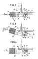
- FIG. 2 shows, in side view, a locking device 20 composed, in known manner, of a longitudinal axis 21 and of a carriage 23 movable by screwing along this axis 21.
- This carriage 23 comprises a knurled button 24 allowing the screwing or unscrewing, therefore the maneuvering of the carriage, a fixed device 25 allowing the locking device to be hooked on the tab 3 of the housing, and a rear stop 26, retractable by intermediate of a ring 27, which is supported during the removal of the housing, behind the face 2 of the housing ( Figure 3).
- the locking device could comprise, conversely, a retractable hooking device and a fixed rear cleat.
- Figure 2 shows the particular shape of the yoke 17, fixed under the bottom 11 of the plate 10, and provided with an inclined light 30 ending at its upper end by two notches stop 31, 33, and at its lower end by a stop notch 32.
- the end of the axis 21 comprises, perpendicular to itself, an articulation rod 22, guided between the two ears of the yoke 17, which moves in each light 30 and which takes support, as the case may be, in either of the stop notches 31, 32, 33.
- This figure 2 shows the case of the establishment of the housing.
- the articulation rod bears in the stop notch 31 and the screwing of the knurled button 24 causes the housing to move according to the arrow F.
- Figure 3 shows the case of maintaining the housing after plugging in.
- the articulation rod 22 is supported in the stop notch 32 and the latch, thus inclined at an angle ⁇ , induces a vertical component Fv which opposes the lifting of the housing when the latter is installed in a machine in service.
- Figure 4 shows the case of removing the housing.
- the rod 22 is supported in the stop notch 33, the cleat 26 is supported behind the face, and the unscrewing of the knurled button 24 thus causes the displacement of the housing according to the arrow F.
- the operator holds the housing by its handle 4, places it on the plate and pushes it until the female part of the connector comes into contact with the male part 15. He then hooks each locking device on the tab 3 corresponding, and screws the knurled knobs which causes the housing to move along the OX+ axis until the connector is correctly inserted. He then unscrews these knurled knobs, inclines the locking devices by bringing each articulation rod into the notches 32 and then re-screws the knurled knobs to block the housing. The installation is thus completed.
- a case removal operation is carried out as follows:
- the operator unscrews the knurled knobs, straightens the locking devices, sets up the cleats 26 by turning the ring 27, and finally brings each articulation rod into the notches 33.
Landscapes
- Engineering & Computer Science (AREA)
- Microelectronics & Electronic Packaging (AREA)
- Casings For Electric Apparatus (AREA)
- Details Of Connecting Devices For Male And Female Coupling (AREA)
Applications Claiming Priority (2)
| Application Number | Priority Date | Filing Date | Title |
|---|---|---|---|
| FR8705672 | 1987-04-22 | ||
| FR8705672A FR2614372B1 (fr) | 1987-04-22 | 1987-04-22 | Dispositif de verrouillage d'un boitier d'equipements electroniques sur un plateau |
Publications (2)
| Publication Number | Publication Date |
|---|---|
| EP0288859A1 true EP0288859A1 (de) | 1988-11-02 |
| EP0288859B1 EP0288859B1 (de) | 1992-06-10 |
Family
ID=9350363
Family Applications (1)
| Application Number | Title | Priority Date | Filing Date |
|---|---|---|---|
| EP19880106140 Expired - Lifetime EP0288859B1 (de) | 1987-04-22 | 1988-04-18 | Verriegelungsvorrichtung eines Gehäuses mit elektronischen Geräten auf einem Gestell |
Country Status (5)
| Country | Link |
|---|---|
| US (1) | US4882655A (de) |
| EP (1) | EP0288859B1 (de) |
| DE (1) | DE3871849T2 (de) |
| ES (1) | ES2032487T3 (de) |
| FR (1) | FR2614372B1 (de) |
Cited By (1)
| Publication number | Priority date | Publication date | Assignee | Title |
|---|---|---|---|---|
| EP3836764A1 (de) * | 2019-12-12 | 2021-06-16 | Airbus Defence and Space GmbH | Adapterelement und bauteil zur verbindung miteinander |
Families Citing this family (15)
| Publication number | Priority date | Publication date | Assignee | Title |
|---|---|---|---|---|
| FR2652940B1 (fr) * | 1989-10-05 | 1994-03-11 | Bull Sa | Dispositif de fixation de peripheriques d'ordinateur. |
| US5087088A (en) * | 1991-02-13 | 1992-02-11 | The United States Of America As Represented By The Administrator Of The National Aeronautics And Space Administration | J-hook latching device |
| US5458432A (en) * | 1994-02-09 | 1995-10-17 | Honeywell Inc. | Unit tray hold down mechanism |
| US6022327A (en) * | 1998-05-04 | 2000-02-08 | Chang; Henry Ping | Facial steamer machine with detachable function units |
| US7733658B1 (en) | 2001-12-14 | 2010-06-08 | Perkins Technical Services, Inc. | Integrated power supply and platform for military radio |
| US6784570B1 (en) * | 2001-12-14 | 2004-08-31 | Perkins Technical Services, Inc. | Integrated power supply and platform for military radio |
| US6544052B1 (en) * | 2002-02-27 | 2003-04-08 | Honeywell International Inc. | Bracket for guiding an electronic module during extraction from a shelving system |
| US7643309B1 (en) * | 2002-07-18 | 2010-01-05 | Rockwell Collins, Inc. | Ruggedized electronics sub-system module |
| US6665189B1 (en) * | 2002-07-18 | 2003-12-16 | Rockwell Collins, Inc. | Modular electronics system package |
| US7639511B2 (en) * | 2006-04-19 | 2009-12-29 | International Business Machines Corporation | Adjustable attachment for electronic assemblies |
| US8107257B2 (en) * | 2009-05-04 | 2012-01-31 | L-3 Communications Avionics Systems, Inc. | Electronic assembly retaining system |
| FR3028840B1 (fr) * | 2014-11-26 | 2016-12-09 | Airbus Operations Sas | Bati de support pour au moins un equipement electronique d'aeronef, dispositif de support et aeronef correspondants |
| CN104507289B (zh) * | 2014-12-16 | 2017-12-19 | 中航光电科技股份有限公司 | 用于机箱的助拔锁紧器 |
| US11888273B1 (en) | 2020-06-12 | 2024-01-30 | Perkins Technical Services, Inc. | Power supply docking station with internal battery power |
| CN113629446B (zh) * | 2021-07-20 | 2023-11-14 | 中航光电科技股份有限公司 | 回转式快锁快分锁定器及模块式连接器 |
Citations (4)
| Publication number | Priority date | Publication date | Assignee | Title |
|---|---|---|---|---|
| FR2229611A1 (de) * | 1973-05-14 | 1974-12-13 | Hollingsbad Pryor Enterprises | |
| US3872734A (en) * | 1972-04-12 | 1975-03-25 | Rockwell International Corp | Hold-down/extraction apparatus |
| EP0071559A1 (de) * | 1981-07-28 | 1983-02-09 | Rexnord Inc. | Hold-down Befestigungsvorrichtung |
| US4506439A (en) * | 1983-09-01 | 1985-03-26 | Barry Wright Corporation | Apparatus for securing an electronic unit to an avionics tray |
Family Cites Families (5)
| Publication number | Priority date | Publication date | Assignee | Title |
|---|---|---|---|---|
| FR548736A (fr) * | 1922-03-11 | 1923-01-22 | Guerard | Appareil annonciateur automatique |
| FR2163415B1 (de) * | 1971-12-15 | 1974-08-02 | Stop Choc Schwi Gungstec | |
| IT1085819B (it) * | 1977-06-01 | 1985-05-28 | Itw Fastex Italia Spa | Dispositivo per inserire e disinserire schede a circuiti stampati per apparecchiature elettroniche in genere |
| GB2118782B (en) * | 1982-03-25 | 1985-08-14 | Vg Instr Ltd | Rack mounting system for electrical or electronic apparatus |
| US4497528A (en) * | 1982-08-06 | 1985-02-05 | Sperry Corporation | Avionics chassis insertion/extraction mechanism |
-
1987
- 1987-04-22 FR FR8705672A patent/FR2614372B1/fr not_active Expired
-
1988
- 1988-04-18 DE DE8888106140T patent/DE3871849T2/de not_active Expired - Fee Related
- 1988-04-18 EP EP19880106140 patent/EP0288859B1/de not_active Expired - Lifetime
- 1988-04-18 ES ES88106140T patent/ES2032487T3/es not_active Expired - Lifetime
- 1988-04-20 US US07/183,960 patent/US4882655A/en not_active Expired - Fee Related
Patent Citations (4)
| Publication number | Priority date | Publication date | Assignee | Title |
|---|---|---|---|---|
| US3872734A (en) * | 1972-04-12 | 1975-03-25 | Rockwell International Corp | Hold-down/extraction apparatus |
| FR2229611A1 (de) * | 1973-05-14 | 1974-12-13 | Hollingsbad Pryor Enterprises | |
| EP0071559A1 (de) * | 1981-07-28 | 1983-02-09 | Rexnord Inc. | Hold-down Befestigungsvorrichtung |
| US4506439A (en) * | 1983-09-01 | 1985-03-26 | Barry Wright Corporation | Apparatus for securing an electronic unit to an avionics tray |
Cited By (1)
| Publication number | Priority date | Publication date | Assignee | Title |
|---|---|---|---|---|
| EP3836764A1 (de) * | 2019-12-12 | 2021-06-16 | Airbus Defence and Space GmbH | Adapterelement und bauteil zur verbindung miteinander |
Also Published As
| Publication number | Publication date |
|---|---|
| FR2614372B1 (fr) | 1989-06-09 |
| US4882655A (en) | 1989-11-21 |
| ES2032487T3 (es) | 1993-02-16 |
| DE3871849D1 (de) | 1992-07-16 |
| FR2614372A1 (fr) | 1988-10-28 |
| EP0288859B1 (de) | 1992-06-10 |
| DE3871849T2 (de) | 1993-04-01 |
Similar Documents
| Publication | Publication Date | Title |
|---|---|---|
| EP0288859B1 (de) | Verriegelungsvorrichtung eines Gehäuses mit elektronischen Geräten auf einem Gestell | |
| FR2619257A1 (fr) | Ensemble de connecteur electrique a debranchement rapide | |
| EP2293388B1 (de) | Vorrichtung zum Erden eines Hochspannungskabels | |
| EP3242360B1 (de) | Verriegelungsvorrichtung für elektrische anschlüsse, und mit einer solchen vorrichtung ausgestattete elektrische anschlüsse | |
| FR2979565A3 (fr) | Outil electrique avec lame remplacable | |
| EP0437124B1 (de) | Klemmvorrichtung für nebeneinander liegende modulare elektrische Geräte und modulares Gerät mit einer solchen Vorrichtung | |
| EP3703091B1 (de) | Elektrische schaltvorrichtung für schienenfahrzeug, und mit dieser vorrichtung ausgestattetes schienenfahrzeug | |
| FR2756879A1 (fr) | Dispositif d'assemblage d'un corps de revolution sur un support, au moyen d'une agrafe | |
| EP0347294B1 (de) | Roboterhandgelenk zum Zusammenfügen von z.B. eines Steckers mit seinem Komplementärstecker | |
| FR2462797A1 (fr) | Dispositif d'immobilisation d'un connecteur femelle dans un connecteur male pour une liaison electrique coaxiale | |
| EP1122398A1 (de) | Befestigungsvorrichtung und Betätigungseinrichtung für eine diese Befestigungsvorrichtung enthaltende Schliess- oder Sonnenschutzeinrichtung | |
| EP0576339A1 (de) | Anschlussklemme für elektrische Leiter | |
| EP0478403B1 (de) | Befestigungseinrichtung für einen Kühler eines Kraftfahrzeugmotors | |
| EP0151063B1 (de) | Vorrichtung zum automatischen oder manuellen Öffnen von Türen von Behälter von Sicherheitsausrüstung | |
| FR2536238A1 (en) | Mount for car stereo radio | |
| FR2743673A1 (fr) | Support d'appareillage a rapporter sur une boite d'encastrement et sous-ensemble vis-griffe propre a equiper un tel support d'appareillage | |
| EP2190275A1 (de) | Gehäuse für ein elektronisches Modul zur Steuerung einer Maschine | |
| EP0839245B1 (de) | Schliessblech, insbesondere für einen aufzug | |
| KR101752085B1 (ko) | 전자 개폐기의 락킹 구조 | |
| EP1961617A1 (de) | Verfahren zur Entriegelung einer abnehmbaren Designblende eines elektronischen Gerätes und zugehörige Entriegelungsvorrichtung | |
| EP3840974B1 (de) | Modul, vorgesehen zum zusammenbau in einem innenraum eines kraftfahrzeugs | |
| EP1182742B1 (de) | Bewegbares Schutzgitter für die Kontaktstifte eines elektrischen Verbinders sowie mit einem solchen Schutzgitter ausgestatteter Verbinder | |
| FR2773662A1 (fr) | Boitier, en particulier pour bloc autonome d'eclairage de securite | |
| EP1439621B1 (de) | Modulares elektrisches Gerät zum Aufsetzen auf Sammelschienen verschiedener Dicke | |
| EP0903793A1 (de) | Batteriegehäuse für Spielzeug und Spielzeug mit einem solchen Gehäuse |
Legal Events
| Date | Code | Title | Description |
|---|---|---|---|
| PUAI | Public reference made under article 153(3) epc to a published international application that has entered the european phase |
Free format text: ORIGINAL CODE: 0009012 |
|
| AK | Designated contracting states |
Kind code of ref document: A1 Designated state(s): BE DE ES FR GB IT LU NL SE |
|
| 17P | Request for examination filed |
Effective date: 19890502 |
|
| 17Q | First examination report despatched |
Effective date: 19910819 |
|
| GRAA | (expected) grant |
Free format text: ORIGINAL CODE: 0009210 |
|
| AK | Designated contracting states |
Kind code of ref document: B1 Designated state(s): BE DE ES FR GB IT LU NL SE |
|
| REF | Corresponds to: |
Ref document number: 3871849 Country of ref document: DE Date of ref document: 19920716 |
|
| GBT | Gb: translation of ep patent filed (gb section 77(6)(a)/1977) | ||
| ITF | It: translation for a ep patent filed | ||
| REG | Reference to a national code |
Ref country code: ES Ref legal event code: FG2A Ref document number: 2032487 Country of ref document: ES Kind code of ref document: T3 |
|
| PLBE | No opposition filed within time limit |
Free format text: ORIGINAL CODE: 0009261 |
|
| STAA | Information on the status of an ep patent application or granted ep patent |
Free format text: STATUS: NO OPPOSITION FILED WITHIN TIME LIMIT |
|
| 26N | No opposition filed | ||
| EPTA | Lu: last paid annual fee | ||
| PGFP | Annual fee paid to national office [announced via postgrant information from national office to epo] |
Ref country code: FR Payment date: 19941230 Year of fee payment: 8 |
|
| PGFP | Annual fee paid to national office [announced via postgrant information from national office to epo] |
Ref country code: ES Payment date: 19950112 Year of fee payment: 8 |
|
| PGFP | Annual fee paid to national office [announced via postgrant information from national office to epo] |
Ref country code: SE Payment date: 19950119 Year of fee payment: 8 |
|
| EAL | Se: european patent in force in sweden |
Ref document number: 88106140.2 |
|
| PGFP | Annual fee paid to national office [announced via postgrant information from national office to epo] |
Ref country code: LU Payment date: 19950201 Year of fee payment: 8 |
|
| PGFP | Annual fee paid to national office [announced via postgrant information from national office to epo] |
Ref country code: BE Payment date: 19950208 Year of fee payment: 8 |
|
| PGFP | Annual fee paid to national office [announced via postgrant information from national office to epo] |
Ref country code: GB Payment date: 19950220 Year of fee payment: 8 |
|
| PGFP | Annual fee paid to national office [announced via postgrant information from national office to epo] |
Ref country code: DE Payment date: 19950221 Year of fee payment: 8 |
|
| PGFP | Annual fee paid to national office [announced via postgrant information from national office to epo] |
Ref country code: NL Payment date: 19950430 Year of fee payment: 8 |
|
| PG25 | Lapsed in a contracting state [announced via postgrant information from national office to epo] |
Ref country code: LU Free format text: LAPSE BECAUSE OF NON-PAYMENT OF DUE FEES Effective date: 19960418 Ref country code: GB Effective date: 19960418 |
|
| PG25 | Lapsed in a contracting state [announced via postgrant information from national office to epo] |
Ref country code: SE Effective date: 19960419 Ref country code: ES Free format text: LAPSE BECAUSE OF NON-PAYMENT OF DUE FEES Effective date: 19960419 |
|
| PG25 | Lapsed in a contracting state [announced via postgrant information from national office to epo] |
Ref country code: BE Effective date: 19960430 |
|
| BERE | Be: lapsed |
Owner name: VIBRACHOC Effective date: 19960430 |
|
| PG25 | Lapsed in a contracting state [announced via postgrant information from national office to epo] |
Ref country code: NL Effective date: 19961101 |
|
| GBPC | Gb: european patent ceased through non-payment of renewal fee |
Effective date: 19960418 |
|
| PG25 | Lapsed in a contracting state [announced via postgrant information from national office to epo] |
Ref country code: FR Effective date: 19961227 |
|
| PG25 | Lapsed in a contracting state [announced via postgrant information from national office to epo] |
Ref country code: DE Effective date: 19970101 |
|
| NLV4 | Nl: lapsed or anulled due to non-payment of the annual fee |
Effective date: 19961101 |
|
| EUG | Se: european patent has lapsed |
Ref document number: 88106140.2 |
|
| REG | Reference to a national code |
Ref country code: FR Ref legal event code: ST |
|
| REG | Reference to a national code |
Ref country code: ES Ref legal event code: FD2A Effective date: 19990405 |
|
| PG25 | Lapsed in a contracting state [announced via postgrant information from national office to epo] |
Ref country code: IT Free format text: LAPSE BECAUSE OF NON-PAYMENT OF DUE FEES;WARNING: LAPSES OF ITALIAN PATENTS WITH EFFECTIVE DATE BEFORE 2007 MAY HAVE OCCURRED AT ANY TIME BEFORE 2007. THE CORRECT EFFECTIVE DATE MAY BE DIFFERENT FROM THE ONE RECORDED. Effective date: 20050418 |