EP0288920A2 - Dispositif de coupe pour tissus en mouvement - Google Patents
Dispositif de coupe pour tissus en mouvement Download PDFInfo
- Publication number
- EP0288920A2 EP0288920A2 EP88106473A EP88106473A EP0288920A2 EP 0288920 A2 EP0288920 A2 EP 0288920A2 EP 88106473 A EP88106473 A EP 88106473A EP 88106473 A EP88106473 A EP 88106473A EP 0288920 A2 EP0288920 A2 EP 0288920A2
- Authority
- EP
- European Patent Office
- Prior art keywords
- roller
- web
- circular knife
- needle
- cutting device
- Prior art date
- Legal status (The legal status is an assumption and is not a legal conclusion. Google has not performed a legal analysis and makes no representation as to the accuracy of the status listed.)
- Granted
Links
Images

Classifications
-
- D—TEXTILES; PAPER
- D06—TREATMENT OF TEXTILES OR THE LIKE; LAUNDERING; FLEXIBLE MATERIALS NOT OTHERWISE PROVIDED FOR
- D06H—MARKING, INSPECTING, SEAMING OR SEVERING TEXTILE MATERIALS
- D06H7/00—Apparatus or processes for cutting, or otherwise severing, specially adapted for the cutting, or otherwise severing, of textile materials
- D06H7/04—Apparatus or processes for cutting, or otherwise severing, specially adapted for the cutting, or otherwise severing, of textile materials longitudinally
- D06H7/06—Removing selvedge edges
Definitions
- the invention relates to a cutting device for running webs for cutting off the web edges, which are needled on needle chains from tensioning machines or the like.
- a cutting device for running webs for cutting off the web edges, which are needled on needle chains from tensioning machines or the like.
- a hold-down roller that overlaps the needle chain and the web
- a circular knife on the same side of the web in its direction of travel following the hold-down roller and with a circular knife on the on the other web side, the web edge against the hold-down roller and the circular knife lifting the needle chain out of the needle chain with a coaxial support roller that extends towards the center of the web.
- Such cutting devices are known and are used to cut the needled web edges at the outlet of tensioning and drying machines, so that the trimmed product is free of needle punctures.
- the cutting device is always used in pairs for trimming the web on both sides, the needle wheel lying on the inside next to the needle chains rotating in the tensioning machine with the help of its support roller takes the web out of the needles of the needle chain and feeds it to the circular knife which, when cutting the web, dips into an annular groove of the needle wheel, the needle wheel supporting the web against the cutting pressure of the circular knife.
- the needled edge strip is cut off directly on the needle wheel, which in turn is provided with a ring of needles that grip the edge strips of the material web, in order to prevent the material web from slipping across the needle wheel during the cutting process.
- the hold-down roller arranged in front of the pinwheel in the running direction serves to prevent premature needling of the web edge from the needle chain.
- a tensioning roller is arranged in a cutting device of the type mentioned at the outset in DE-GM 85 10 268 in the direction of travel of the web in front of the support roller on the same web side as the hold-down roller, the one with the support roller passing through the web
- Running roller gap forms, which leads to a cross-tension adjustable in size in the web, so that the web can move more or less, following the cross-tension, during the transition from the needle chain to the needles of the needle wheel, which leads to the narrower edge strips , the stronger the crossfeed of the web is.
- the invention is based on the object of designing a cutting device of the type mentioned at the outset in such a way that minimal edge strip widths are possible even without the goods being fed in transversely.
- the circular knife in the direction of travel of the web at a distance behind the pinwheel and on the same side the web like the circular knife, has a guide roller between the pinwheel and the circular knife, and on the other side of the web behind the guide roller, a fixing roller is arranged opposite the circular knife, which supports the edge of the web against the cutting forces of the circular knife, that the fixing roller and the guide roller each have their circumference a fixing device securing the edge of the web against transverse displacements, and that the guide roller, the fixing roller and the circular knife are axially adjustable, that is to say transversely to the direction of travel of the web and the needle chain, and with a distance which enables this adjustment also via the needle chain and the pinwheel Needle chain and the Abnadelrad are arranged.
- the interface of the pinwheel is moved at such a distance behind it and over the needle chain that the needle chain or the pinwheel cannot axially adjust the circular knife and the fixing and guide rollers assigned to the latter even when the circular knife and the fixing - And guide rollers are adjusted up to the needle chain itself, which makes it possible to lay the cutting line of the circular knife as close as desired to the row of stitches originating from the needle chain or even to let it coincide with it, which is the smallest possible width for the edge strips to be cut off or cut off.
- a particularly advantageous embodiment of the invention which has a particularly advantageous effect on the guiding conditions of the edge of the web to be trimmed, is characterized in that the guide roller and the fixing roller are located approximately at the same distance from the needle chain and form a gap between them that is passed through by the web.
- the guide roller and the fixing roller are expediently mounted together on a bearing block, which also has bearing and drive devices for the circular knife wearing.
- the bearing block is preferably displaceable and adjustable in the direction of the mutually parallel axes of the guide roller and fixing roller, which is in turn mounted on the machine frame so that it can be pivoted away from the web is.
- the circular knife can also be easily adjusted in relation to the fixing roller in accordance with the desired cutting conditions. This arrangement is particularly recommended even if, in a further embodiment of the invention, the fixing roller has an annular groove running in the circumferential direction, into which the circular knife dips with its edge forming the knife edge, because then the immersion depth of the circular knife via the adjustment of the swivel arm as necessary or Expediency can be chosen.
- the fixing device can expediently also consist of an adhesive covering made of rubber or plastic of high static friction value and of a press roller pressing the material web against the adhesive coating relative to the fixing roller or guide roller, the material web in front of the circular knife between the fixing roller or guide roller and the press roller runs through.
- the adhesive coating can also be formed by a rubber or plastic brush made of the appropriate material.
- the guide roller and the fixing roller each with their own coaxial support roller, which extends towards the center of the web, in order to keep surface distortions in the edge area of the web as low as possible and, if possible, only to create the largest possible area so that wrinkles form be avoided.
- the support rollers of the guide roller and the fixing roller taper conically towards the free roller end and are cambered at the end.
- the cone angle depends on the material Depending on the type of web, but generally be chosen so that the half cone angle is about 5 ° to 10 °.
- the guide roller and the fixing roller are preferably each formed in one piece with their support roller. It may also be advisable to make the distance between the support rollers adjustable in order to prevent wrinkles in the region of the support rollers.
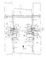
- the web is designated 1, its running direction by the arrow 2.
- the web 1 is fed in a tensioning machine, of which only the needle chains 3 are indicated, on which the web edges are needled, to the cutting devices generally designated 4, which have the task of providing the edge strips 5 of the needle chains 3 with the needle chains 3 Cut material web 1 so that the product so trimmed is free of needle punctures.
- the cut off edge strip 5 should be as narrow as possible in order to avoid unnecessary loss of goods.
- each cutting device 4 has a hold-down roller 27 which overlaps the needle chain 3 and the web 1, furthermore a circular knife 8 on the same side of the web 1 in the direction of travel of the hold-down roller 27, and one on the other side of the web between the hold-down roller 27 and the circular knife 8 lying needle wheel 9, which lifts the edge of the web against the hold-down roller 27 and the circular knife 8 out of the needle chain 3.
- the needle wheel 9 is provided with a coaxial support roller 10, which extends towards the center of the web, and is cambered at 10.1 at the free end, but is essentially cylindrical in the rest.
- the needle wheel 9 itself has none in the exemplary embodiment Needles, but a smooth guide surface for the web 1.
- the circular knife 8 is arranged in the direction of travel of the web 1 at a distance behind the needle wheel 9.
- a guide roller 7 on the same web side as the latter.
- a fixing roller 11 is arranged behind the guide roller 7 opposite the circular knife 8, which fixes the web edge against the cutting forces of the circular knife 8 supports and how the guide roller 7 is provided over its circumference with a fixing device securing the web edge against transverse displacements, in the exemplary embodiment each a ring of needles 11.1, 7.1.
- the fixing roller 11 or guide roller 7 as the fixing device can also have an adhesive covering made of rubber or plastic of high static friction value, the web 1 in front of the circular knife 8 between the fixing roller 11 and one in FIG. 2 only in connection with the fixing roller 11, shown in dashed lines, passes through the pressing roller 12, which presses the web 1 against the adhesive coating and thus secures it against lateral displacements on the fixing roller 11 or the guide roller 7 during the cutting process.
- the guide roller 7, the fixing roller 11 and the circular knife 8 can be adjusted axially, ie transversely to the direction of travel of the web 1 and the needle chain 3, that is to say in the direction of the double arrow 13, and can be locked in their respective settings.
- the guide roller 7, the fixing roller 11 and the circular knife 8 are arranged at such a distance from the needle chain 3 and the needle wheel 9 that the guide roller 7, the fixing roller 11 and the circular knife 8 also up to the needle chain 3 itself and on the needle wheel 9 can be adjusted past, this axial adjustability of the guide roller 7, the fixing roller 11 and the circular knife 8 can be hindered neither by the needle chain 3 nor by the needle wheel 9.
- the guide roller 7 and the fixing roller 11 are approximately at the same distance from the needle chain 3 and form between them a gap 14 through which the web 1 passes.
- the guide roller 7 and the fixing roller 11 are mounted together on a bearing block 15, which is also a bearing and drive device 16 for the circular knife 8 carries.
- the bearing block 15 is displaceable and adjustable in the direction of the mutually parallel axes of the guide roller 7 and the fixing roller 11 on a carrier part 28 which is pivotally mounted about the axis 29 on the machine frame 26, so that the carrier part with the guide roller 7, fixing roller 11 and circular knife 8 can be pivoted away from the web 1 in the direction of arrow 30 in order to be able to insert the web more easily into the cutting device or to be able to interrupt the cutting process at all.
- the bearing and the drive device 16 of the circular knife 8 are connected to the bearing block 15 via a swivel arm 17 which can be adjusted about the axis 25, which enables the circular knife 8 to be adjusted relative to the fixing roller 11 in a simple manner.
- the fixing roller 11 has an annular groove 11.2 running in the circumferential direction, into which the circular knife 8 with its edge forming the knife edge is immersed to a greater or lesser depth depending on the setting of the swivel arm 17.
- the axis of the circular knife 8 can be adjusted slightly obliquely with respect to the axes of the guide roller 7 or fixing roller 11 in order to obtain a clearance angle for a better cut.
- this adjustability is not shown in the drawing because of the better overview.
- the guide roller 7 and the fixing roller 11 are each provided with their own, coaxial support roller 18, 19 extending towards the center of the web. These support rollers 18, 19 taper towards the free end of the roller essentially conically with a half cone angle 20 of approximately 5 ° to 10 ° and are cambered at 21 at the end.
- the guide roller 7 and the fixing roller 11 are each in one piece trained with their support roller 18, 19. The distance between the support rollers 18, 19 can be adjustable, but this is not shown in detail in the drawing.
- These support rollers 18, 19 serve the purpose of guiding the web 1 through the cutters 4 as free of distortion as possible and avoiding wrinkles if possible.
- the guide crossbeam 22 provided in the running direction behind the circular knife 8 and overflowing from the material web 1 is arranged somewhat higher than the fixing roller 11 with respect to the needle chain 3.
- the circular knife 8 can be easily adjusted with its cutting line outward beyond the needle chain 3, so that the cutting line can even coincide with the row of needle punctures 6 in the web 1 originating from the needle chain 3.
- the needle insertion row from the guide roller 7 and the fixing roller 11 is located outside the cutting line and still in the area or even outside the insertion row 6 originating from the needle chain 3 in the edge strip 5 to be cut or cut off.
Landscapes
- Engineering & Computer Science (AREA)
- Textile Engineering (AREA)
- Treatment Of Fiber Materials (AREA)
- Details Of Cutting Devices (AREA)
- Advancing Webs (AREA)
- Nonwoven Fabrics (AREA)
Applications Claiming Priority (2)
| Application Number | Priority Date | Filing Date | Title |
|---|---|---|---|
| DE8706248U DE8706248U1 (de) | 1987-04-30 | 1987-04-30 | Schneidgerät für laufende Warenbahnen |
| DE8706248U | 1987-04-30 |
Publications (3)
| Publication Number | Publication Date |
|---|---|
| EP0288920A2 true EP0288920A2 (fr) | 1988-11-02 |
| EP0288920A3 EP0288920A3 (en) | 1989-11-08 |
| EP0288920B1 EP0288920B1 (fr) | 1991-12-04 |
Family
ID=6807561
Family Applications (1)
| Application Number | Title | Priority Date | Filing Date |
|---|---|---|---|
| EP88106473A Expired - Lifetime EP0288920B1 (fr) | 1987-04-30 | 1988-04-22 | Dispositif de coupe pour tissus en mouvement |
Country Status (3)
| Country | Link |
|---|---|
| EP (1) | EP0288920B1 (fr) |
| DE (2) | DE8706248U1 (fr) |
| ES (1) | ES2026597T3 (fr) |
Cited By (6)
| Publication number | Priority date | Publication date | Assignee | Title |
|---|---|---|---|---|
| FR2681343A1 (fr) * | 1991-09-16 | 1993-03-19 | Fehrer Textilmasch | Dispositif pour placer un ruban de voile de carde sur une bande-support tournant sans fin. |
| CN107475982A (zh) * | 2017-10-11 | 2017-12-15 | 江苏安卡新材料科技有限公司 | 一种高性能纤维混纺机织布边缘处理装置 |
| CN107879176A (zh) * | 2017-11-01 | 2018-04-06 | 中国船舶重工集团公司第七0五研究所 | 一种用于自动裁布机的纠偏纵切系统 |
| CN112323443A (zh) * | 2020-10-14 | 2021-02-05 | 江门市粤新化纤有限公司 | 一种无纺布生产用边角修剪装置 |
| CN112900063A (zh) * | 2021-01-15 | 2021-06-04 | 蔡影抒 | 一种无纺布切边设备 |
| CN114045660A (zh) * | 2021-10-22 | 2022-02-15 | 南京迪莫菲亚纺织品有限公司 | 一种纺织用布匹毛边自动去除装置 |
Families Citing this family (3)
| Publication number | Priority date | Publication date | Assignee | Title |
|---|---|---|---|---|
| DE3834572A1 (de) * | 1988-10-11 | 1990-04-12 | Monforts Gmbh & Co A | Vorrichtung zum abtrennen der leisten von stoffbahnen und verfahren zum betrieb der vorrichtung |
| DE3834571A1 (de) * | 1988-10-11 | 1990-04-12 | Monforts Gmbh & Co A | Vorrichtung zum beschneiden der leisten von stoffbahnen |
| CN107571320B (zh) * | 2017-11-01 | 2019-03-19 | 中国船舶重工集团公司第七0五研究所 | 一种用于自动裁布机的可脱布式针板组件 |
Family Cites Families (5)
| Publication number | Priority date | Publication date | Assignee | Title |
|---|---|---|---|---|
| DE479223C (de) * | 1929-07-13 | Erich Ullmann | Stoffableistmaschine | |
| DE1092430B (de) * | 1958-05-29 | 1960-11-10 | Krantz Soehne H | Vorrichtung zum Abschneiden und Abfuehren der Leisten von Warenbahnen |
| FR1393167A (fr) * | 1963-05-30 | 1965-03-19 | Dispositif de coupe des lisières de nappes d'étoffe | |
| GB1273348A (en) * | 1968-08-08 | 1972-05-10 | Courtaulds Ltd | Improvements in and relating to pin stenters |
| DE8510268U1 (de) * | 1985-04-06 | 1985-05-23 | Erhardt & Leimer GmbH, 8900 Augsburg | Schneidgerät für laufende Warenbahnen |
-
1987
- 1987-04-30 DE DE8706248U patent/DE8706248U1/de not_active Expired
-
1988
- 1988-04-22 ES ES198888106473T patent/ES2026597T3/es not_active Expired - Lifetime
- 1988-04-22 EP EP88106473A patent/EP0288920B1/fr not_active Expired - Lifetime
- 1988-04-22 DE DE8888106473T patent/DE3866583D1/de not_active Expired - Fee Related
Cited By (10)
| Publication number | Priority date | Publication date | Assignee | Title |
|---|---|---|---|---|
| FR2681343A1 (fr) * | 1991-09-16 | 1993-03-19 | Fehrer Textilmasch | Dispositif pour placer un ruban de voile de carde sur une bande-support tournant sans fin. |
| DE4229579A1 (de) * | 1991-09-16 | 1993-04-01 | Fehrer Textilmasch | Vorrichtung zum aufbringen eines vliesbandes auf eine endlos umlaufende traegerbahn |
| DE4229579C2 (de) * | 1991-09-16 | 1995-11-09 | Fehrer Textilmasch | Vorrichtung zum Aufbringen eines Vliesbandes auf eine endlos umlaufende Trägerbahn |
| CN107475982A (zh) * | 2017-10-11 | 2017-12-15 | 江苏安卡新材料科技有限公司 | 一种高性能纤维混纺机织布边缘处理装置 |
| CN107475982B (zh) * | 2017-10-11 | 2023-06-16 | 莱特丝(江苏)新材料科技有限公司 | 一种高性能纤维混纺机织布边缘处理装置 |
| CN107879176A (zh) * | 2017-11-01 | 2018-04-06 | 中国船舶重工集团公司第七0五研究所 | 一种用于自动裁布机的纠偏纵切系统 |
| CN112323443A (zh) * | 2020-10-14 | 2021-02-05 | 江门市粤新化纤有限公司 | 一种无纺布生产用边角修剪装置 |
| CN112900063A (zh) * | 2021-01-15 | 2021-06-04 | 蔡影抒 | 一种无纺布切边设备 |
| CN114045660A (zh) * | 2021-10-22 | 2022-02-15 | 南京迪莫菲亚纺织品有限公司 | 一种纺织用布匹毛边自动去除装置 |
| CN114045660B (zh) * | 2021-10-22 | 2023-03-14 | 浙江凯硕纺织有限公司 | 一种纺织用布匹毛边自动去除装置 |
Also Published As
| Publication number | Publication date |
|---|---|
| EP0288920B1 (fr) | 1991-12-04 |
| EP0288920A3 (en) | 1989-11-08 |
| ES2026597T3 (es) | 1992-05-01 |
| DE3866583D1 (de) | 1992-01-16 |
| DE8706248U1 (de) | 1987-06-25 |
Similar Documents
| Publication | Publication Date | Title |
|---|---|---|
| DE3013617A1 (de) | Spaltschere fuer papier | |
| DD153320A5 (de) | Vorrichtung zur foerderung und fuehrung einer materialbahn | |
| EP2815857A2 (fr) | Ciseaux | |
| DE3715917A1 (de) | Maschine zum beiderseitigen boerdeln und einziehen zylindrischer dosenruempfe | |
| DE3727888A1 (de) | Textilbahnausgabevorrichtung | |
| EP0288920B1 (fr) | Dispositif de coupe pour tissus en mouvement | |
| DE3319974A1 (de) | Einrichtung fuer die laengsfuehrung eines endlosen foerderbandes | |
| DE2428113C2 (de) | Vorrichtung zum einseitig kantengeraden Aufwickeln von Warenbahnen | |
| CH693985A5 (fr) | Vorrichtung und Verfahren zum Schneiden einer Materialbahn, insbesondere in einer Rotationsdruckmaschine. | |
| DE3335430C2 (fr) | ||
| EP2276688A1 (fr) | Dispositif et procédé d'enroulement de matériaux en forme de bande | |
| DE102013104978B4 (de) | Maschine zum Aufwickeln von bahnförmigen Materialien | |
| EP0019295B1 (fr) | Procédé et installation pour l'apprêtage de pièces textiles | |
| EP0694019B1 (fr) | Dispositif pour separer un produit d'une bande defilant en continu | |
| DD202125A5 (de) | Papierbahn-fuehrungsvorrichtung | |
| DE4016526C2 (de) | Vorrichtung und Verfahren zum selbsttätigen Wechsel der Aufwickelrichtung in einer mehrachsigen Revolver-Wickelmaschine | |
| DE2513867B2 (de) | Hochleistungs-Zigarettenstrangmaschine mit einem saugradförmigen Tabakstrang-Bandförderer | |
| EP0523419B1 (fr) | Procédé et appareil pour éviter des marques sur des matériaux tubulaires textiles | |
| DE2721980B2 (de) | Prägefolien-Zuführvorrichtung für eine Prägemaschine | |
| EP1972718A2 (fr) | Dispositif de guidage ou de transfert d'une bande en papier, carton ou autre matière fibreuse | |
| DE9405848U1 (de) | Reversierende Abzugsvorrichtung für Schlauchbahnen aus Kunststoffolie | |
| DE3871920T2 (de) | Faltwerkzeug zur herstellung von saumnaehten. | |
| DE10150820A1 (de) | Maschine zur Herstellung oder Behandlung einer Materialbahn | |
| DE19817870B4 (de) | Wickelvorrichtung für eine Bahn | |
| DE60008463T2 (de) | Verfahren und Vorrichtung zum Verbinden der Enden von Materialbahnen, insbesondere Textilbahnen |
Legal Events
| Date | Code | Title | Description |
|---|---|---|---|
| PUAI | Public reference made under article 153(3) epc to a published international application that has entered the european phase |
Free format text: ORIGINAL CODE: 0009012 |
|
| AK | Designated contracting states |
Kind code of ref document: A2 Designated state(s): DE ES IT |
|
| PUAL | Search report despatched |
Free format text: ORIGINAL CODE: 0009013 |
|
| AK | Designated contracting states |
Kind code of ref document: A3 Designated state(s): DE ES IT |
|
| 17P | Request for examination filed |
Effective date: 19890923 |
|
| 17Q | First examination report despatched |
Effective date: 19910515 |
|
| GRAA | (expected) grant |
Free format text: ORIGINAL CODE: 0009210 |
|
| AK | Designated contracting states |
Kind code of ref document: B1 Designated state(s): DE ES IT |
|
| ITF | It: translation for a ep patent filed | ||
| REF | Corresponds to: |
Ref document number: 3866583 Country of ref document: DE Date of ref document: 19920116 |
|
| REG | Reference to a national code |
Ref country code: ES Ref legal event code: FG2A Ref document number: 2026597 Country of ref document: ES Kind code of ref document: T3 |
|
| PLBE | No opposition filed within time limit |
Free format text: ORIGINAL CODE: 0009261 |
|
| STAA | Information on the status of an ep patent application or granted ep patent |
Free format text: STATUS: NO OPPOSITION FILED WITHIN TIME LIMIT |
|
| 26N | No opposition filed | ||
| PGFP | Annual fee paid to national office [announced via postgrant information from national office to epo] |
Ref country code: ES Payment date: 20000406 Year of fee payment: 13 |
|
| PGFP | Annual fee paid to national office [announced via postgrant information from national office to epo] |
Ref country code: DE Payment date: 20000610 Year of fee payment: 13 |
|
| PG25 | Lapsed in a contracting state [announced via postgrant information from national office to epo] |
Ref country code: ES Free format text: LAPSE BECAUSE OF NON-PAYMENT OF DUE FEES Effective date: 20010423 |
|
| PG25 | Lapsed in a contracting state [announced via postgrant information from national office to epo] |
Ref country code: DE Free format text: LAPSE BECAUSE OF NON-PAYMENT OF DUE FEES Effective date: 20020201 |
|
| REG | Reference to a national code |
Ref country code: ES Ref legal event code: FD2A Effective date: 20030203 |
|
| PG25 | Lapsed in a contracting state [announced via postgrant information from national office to epo] |
Ref country code: IT Free format text: LAPSE BECAUSE OF NON-PAYMENT OF DUE FEES;WARNING: LAPSES OF ITALIAN PATENTS WITH EFFECTIVE DATE BEFORE 2007 MAY HAVE OCCURRED AT ANY TIME BEFORE 2007. THE CORRECT EFFECTIVE DATE MAY BE DIFFERENT FROM THE ONE RECORDED. Effective date: 20050422 |