EP0288932A1 - Einheitliche Kassette mit Aufzeichnungs- und Farbband für ein Drucksystem - Google Patents
Einheitliche Kassette mit Aufzeichnungs- und Farbband für ein Drucksystem Download PDFInfo
- Publication number
- EP0288932A1 EP0288932A1 EP88106509A EP88106509A EP0288932A1 EP 0288932 A1 EP0288932 A1 EP 0288932A1 EP 88106509 A EP88106509 A EP 88106509A EP 88106509 A EP88106509 A EP 88106509A EP 0288932 A1 EP0288932 A1 EP 0288932A1
- Authority
- EP
- European Patent Office
- Prior art keywords
- ribbon
- tape
- rewind
- supply
- spool
- Prior art date
- Legal status (The legal status is an assumption and is not a legal conclusion. Google has not performed a legal analysis and makes no representation as to the accuracy of the status listed.)
- Withdrawn
Links
Images
Classifications
-
- B—PERFORMING OPERATIONS; TRANSPORTING
- B41—PRINTING; LINING MACHINES; TYPEWRITERS; STAMPS
- B41J—TYPEWRITERS; SELECTIVE PRINTING MECHANISMS, i.e. MECHANISMS PRINTING OTHERWISE THAN FROM A FORME; CORRECTION OF TYPOGRAPHICAL ERRORS
- B41J3/00—Typewriters or selective printing or marking mechanisms characterised by the purpose for which they are constructed
- B41J3/38—Typewriters or selective printing or marking mechanisms characterised by the purpose for which they are constructed for embossing, e.g. for making matrices for stereotypes
-
- B—PERFORMING OPERATIONS; TRANSPORTING
- B41—PRINTING; LINING MACHINES; TYPEWRITERS; STAMPS
- B41J—TYPEWRITERS; SELECTIVE PRINTING MECHANISMS, i.e. MECHANISMS PRINTING OTHERWISE THAN FROM A FORME; CORRECTION OF TYPOGRAPHICAL ERRORS
- B41J32/00—Ink-ribbon cartridges
Definitions
- the present invention relates generally to a tape-ribbon supply cartridge for use with a lettering apparatus or type composing system, and more particularly, to a unitary tape-ribbon supply cartridge for housing both a supply of lettering tape and ribbon and supplying the same to a lettering station in the above mentioned apparatus.
- the tape-ribbon cartridge of the present invention could be useful in a variety of lettering apparatus or systems embodying various lettering mechanisms, it has particular application to an impact or pressure lettering system of the type described generally in United States Patent Nos. 4,544,289; 4,548,523 and 4,579,056.
- the lettering system described in the above patents contemplates the use of a separate ribbon supply cassette and a separate tape supply cassette for supplying the ribbon and tape in such system.
- the ribbon cassette currently used in such lettering systems is the subject of United States Patent No. 4,595,305, while the tape cassette with supply indicator is the subject of pending United States Patent Application Serial No. 598,554 filed February 17, 1984.
- the present invention relates to a unique, unitary cartridge usable in lettering systems of the type described above in which both the tape and ribbon are supplied from a single cartridge. This significantly reduces the time needed to change the tape and ribbon supplies within the machine and also greatly simplifies the maintenance of inventory. Further, the combined tape-ribbon cartride of the present invention includes a ribbon rewind mechanism which is different than that of current cartridges and permits a significant reduction in the cost of manufacture.
- the unitary tape-ribbon cartridge of the present invention includes separate tape and ribbon housing portions which are joined with one another and lie in a common plane. Means are also provided for guiding and directing the tape and ribbon, one above the other, to a lettering station and means for reversing the direction of movement of the ribbon and guiding the same into a rewind housing portion.
- the rewind housing portion lies in a plane spaced from and generally parallel to the plane of the tape and ribbon supply housing portions and includes a ribbon rewind mechanism having a rotatably supported ribbon rewind spool with an outer peripheral gear portion for rotating such spool.
- the rewind spool includes an inner, cylindrical rewind portion for carrying spent ribbon.
- the unitary tape-ribbon cartridge of the present invention also includes a ribbon drive post and appropriately positioned drive and idler gears for transferring rotational movement of the ribbon drive post to the ribbon rewind spool.
- a unique tension spring is mounted on an interior edge wall of the tape supply housing portion with an end portion bent back upon itself and adapted for engagement with a portion of the ribbon supply spool for creating desired tension. Improved means are also provided for improving and stabilizing the mounting of the cartridge to the machine.
- a further object of the present invention is to provide a unitary cartridge for use in the above apparatus, thus insuring against running out of ribbon despite the apparatus detecting only an "out of tape” condition.
- Another object of the present invention is to provide a unitary tape-ribbon cartridge including a ribbon rewind mechanism which is much less complex and therefore less expensive to manufacture than those currently existing in the prior art.
- a further object of the present invention is to provide a unitary tape-ribbon cartridge which significantly reduces the costs of manufacturing, and reduces the time needed to change, the tape and ribbon in a lettering system of the type described above.
- a further object of the present invention is to provide a unitary tape-ribbon cartridge for a lettering system having a unique tension spring for the ribbon supply and improved means for mounting and stabilizing the cartridge relative to the apparatus.
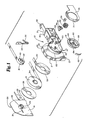
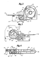
- the cartridge of the present invention is a unitary tape-ribbon cartridge 10 having a tape supply housing portion 11, a ribbon supply housing portion 12 ( Figure 2) and a ribbon rewind housing portion 14. Disposed within these housing portions are a spool of tape supply 15, a ribbon supply 16 and a ribbon rewind spool 18, respectively.
- the tape supply housing portion 11 is defined by a pair of spaced apart side walls 19 and 20 and forward, rearward and top side edges 21, 22 and 24, respectively.
- a generally cylindrical tape spool support 25 is centrally positioned within the housing portion 11 and is integrally formed with and extends perpendicular to the side wall 20 for supporting the spool of tape supply 15.
- the side wall 19 defines a portion of the left side housing cover 26 ( Figure 1) and includes an inwardly extending cylindrical portion adapted and designed to be positioned within the cylindrical spool support 25.
- a latch member 29 is provided within the cylindrical member 28 for connection to a latch opening 30 within the spool support 25 and the side wall 20. The latch member 29 and latch opening 30 function to retain the side cover 26 during assembly.
- An elongated tape viewing slot 31 is provided in the side wall 19 to permit viewing of the tape supply within the housing portion 11 to determine the amount of tape supply remaining.
- the tape supply housing portion 11 is generally closed, except for an open bottom to permit exiting of the tape supply.
- a curved or sloped tape exit ramp and guide member 32 is positioned at the lower forward corner of the tape supply housing portion 11 to assist in guiding the tape out of the housing portion 11 and preventing the same from becoming scratched or bent.
- a tension control member or spring 35 is mounted to the inside surface of the edge wall 21 via the support post 38 integrally formed with the side wall 20. The tension control member or spring 35 extends downwardly along the edge wall 21 to a point near the bottom of the housing 11 at which point it curves back upon itself and terminates in a curved tension control or spring end 36 for engagement with, and controlling the tension on, the ribbon supply spool 16 in the manner described below.
- a support and alignment tab 23 extends outwardly from the rear edge wall 22 for engagement with a portion of the machine to facilitate proper alignment, support and stability of the cartridge relative to the machine.
- a pair of cartridge mounting and alignment openings 33 and 37 are also provided for mounting the cartridge on the machine.
- the spool of tape 15 is mounted on a central core 34 which is rotatably supported with respect to the spool support member 25.
- a pair of tack or other disc members 39 are disposed on opposite sides of the tape supply spool 15 to maintain the tape supply in a compact, tight configuration and to also provide limited resistance to the free rotation of the tape spool 15.
- a short adhesive member 40 is connected to the end of the tape supply 15 to secure the same to a portion of the cartridge prior to use.
- the ribbon supply housing portion 12 is defined by a pair of spaced side walls 41 and 42, a top edge wall 44 and a curved bottom and front side wall 45. As illustrated, the side wall 41 lies in a common plane with the side wall 20 and the side wall 42 is generally coplanar with the side wall 19 and forms a part of the left side cover 26 ( Figure 1).
- a ribbon support post 46 is integrally formed with the side wall 49 and extends outwardly at right angles from such wall to support the spool of ribbon 16.
- the spool 16 includes a central hub portion 48 upon which the ribbon supply is wound and an outwardly extending flange portion 49 connected with an inner end of the hub 48 to provide support for the ribbon suppy spool 16 and to space the ribbon 16 from the side wall 41 to prevent interference therewith.
- the contact end 36 of the tension control member 35 is adapted for engagement with an outer surface portion of the ribbon spool 16 to provide a desired tension or resistance to the rotation of the spool 16.
- the end 36 should exert sufficient force on the spool 16 so that a force between about 5 and 12 grams is needed to pull the ribbon from the spool 16.
- ribbon supply housing portion 12 and the tape supply housing portion 11 lie in a common plane so that they can be supplied to the lettering station with the ribbon 16 directly above the tape 15.
- the cartridge of the present invention also includes an elongated guide member 50 extending forwardly from the ribbon supply housing portion 12 for guiding the ribbon 16 along a ribbon supply path toward the lettering station of the apparatus and then reversing the direction of such tape and guiding the same back along a ribbon rewind path into the rewind housing.
- the member 50 for accomplishing this guiding movement and direction reversal is common in the art.
- the ribbon is directed from the cartridge past an opening 51 in the guide member 50 and around the end 52.
- the opening 51 defines the general position of the lettering station.
- the end 52 includes a pair of diagonal surfaces for changing direction of the ribbon 16 from a forward supply path toward the lettering station to a rearward direction along a rewind path generally parallel to the supply path.
- the ribbon rewind mechanism of the unitary tape-ribbon cartridge of the present invention is illustrated best in Figures 1 and 3.
- the ribbon rewind housing portion 14 lies in a plane spaced from and generally parallel to the tape and ribbon supply housing portions 11 and 12.
- the ribbon rewind housing 14 is defined by an inner side wall 61 and a right side cover portion 70.
- the side wall 61 is defined by the outer surface of the wall which serves as the side wall 20 of the tape supply housing 11.
- An edge wall 63 extends around the ribbon rewind housing portion 14.
- the specific ribbon rewind mechanism of the unitary tape-ribbon cartridge of the present invention includes a ribbon drive post 54 extending through an opening 58 in the side wall 61 and into and through the hollow support post 46 within the ribbon supply housing portion 12 so that a first or outer end of the ribbon drive post 54 is accessible through an opening 53 (Figure 1) in the side wall 42.
- the first end of the ribbon drive post 54 includes an appropriate notch 57 or other means for engagement with a drive member on the lettering machine.
- a second or inner end of the ribbon drive post 54 includes a drive gear member 55 integrally formed with the post 54 and disposed within the ribbon rewind housing 14.
- the drive gear 55 is provided with a plurality of gear teeth about its periphery for engagement with a rotatable idler gear 56.
- the idler gear 56 also includes a plurality of gear teeth about its periphery and is supported for rotation within the rewind housing about the idler gear post 60.
- a spring or bias member 59 is positioned between the second or inner end of the ribbon drive post 54 and the inner surface of the cover plate 70 to bias the drive gear 55 and ribbon drive post 54 toward engagement with the drive member on the lettering apparatus.
- the drive post 54 is adapted to rotate within the ribbon supply spool support 46.
- the ribbon rewind spool 18 includes a central hub portion 66 and is rotatably supported within the rewind housing 14 about the ribbon rewind support post 62.
- the rewind spool 18 also includes a generally cylindrical inwardly positioned ribbon rewind portion 64 and an outer peripheral edge portion 65 having a plurality of gear teeth 65 for engagement with the gear teeth on the idler gear 56.
- the diametrical dimension of the ribbon rewind portion 64 should preferably be as large as possible. A large diametrical dimension is desired to provide as much consistency as possible in the advancement of the ribbon.
- the ribbon 16 in the present cartridge is advanced by rotation of the spool 18 (as a result of microprocessor controlled rotation of the drive post 54), and since the incremental amount of rotation is independent of the amount of ribbon on the rewind spool, the actual amount of advancement will depend on the radial position of the ribbon 16 on the rewind spool 18. In other words, the ribbon advancement will be increased as layers of ribbon are built up on the portion 64.
- the diametrical dimension of the rewind portion 64 should be at least 38 mm in diameter and preferably about 1 1/2 times the outer diameter of the ribbon spool 16 before use. A slight decrease in the diameter of the rewind portion 64 will require significantly more ribbon on the supply spool.
- the ribbon rewind spool 18 also includes a plurality of spokes 68 extending radially outwardly from the central hub 66 to provide means for manually rotating the rewind spool 18. It should be noted that the entire hub 66 and spoke members 68 are positioned inwardly of the outer cover 70 so that no part of the mechanism for manually rotating the spool 18 is located outside of the plane defined by the cover 70.
- the right side cover plate 70 includes a generally circular opening 71 to provide manual access to the rib or spoke members 68. It should be noted that the size of the opening 70 is large enough to permit manual rotation of the spool 18, but small enough to totally cover the gear teeth on the peripheral portion 65.
- the ribbon advancing member within the machine rotates the ribbon drive post 54 in a clockwise direction as viewed in Figure 2.
- This rotational movement of the drive post 54 results in clockwise rotation (as viewed in Figure 3) of the idler gear 56 by virtue of engagement with the drive gear 55.
- Such rotation of the idler gear 56 causes corresponding counterclockwise rotation (as viewed in Figure 3) of the ribbon rewind spool 18.
- Such rotation of the spool 18 causes the spent ribbon to be wound upon the ribbon rewind portion 64, thus pulling the ribbon through the guide system defined by the elongated guide member 50 and from the ribbon supply spool 16.
Landscapes
- Impression-Transfer Materials And Handling Thereof (AREA)
- Printers Characterized By Their Purpose (AREA)
- Handling Of Continuous Sheets Of Paper (AREA)
Applications Claiming Priority (2)
| Application Number | Priority Date | Filing Date | Title |
|---|---|---|---|
| US07/043,463 US4844636A (en) | 1987-04-28 | 1987-04-28 | Unitary tape-ribbon cartridge for lettering system |
| US43463 | 1987-04-28 |
Publications (1)
| Publication Number | Publication Date |
|---|---|
| EP0288932A1 true EP0288932A1 (de) | 1988-11-02 |
Family
ID=21927304
Family Applications (1)
| Application Number | Title | Priority Date | Filing Date |
|---|---|---|---|
| EP88106509A Withdrawn EP0288932A1 (de) | 1987-04-28 | 1988-04-22 | Einheitliche Kassette mit Aufzeichnungs- und Farbband für ein Drucksystem |
Country Status (3)
| Country | Link |
|---|---|
| US (1) | US4844636A (de) |
| EP (1) | EP0288932A1 (de) |
| JP (1) | JPS6456581A (de) |
Cited By (1)
| Publication number | Priority date | Publication date | Assignee | Title |
|---|---|---|---|---|
| WO2012028333A3 (en) * | 2010-09-03 | 2012-06-28 | Gratzer! Technologies Gmbh & Co. Kg | Device and method for transferring decorative rigid bodies onto a substrate |
Families Citing this family (24)
| Publication number | Priority date | Publication date | Assignee | Title |
|---|---|---|---|---|
| US5188469A (en) * | 1988-10-14 | 1993-02-23 | Brother Kogyo Kabushiki Kaisha | Tape feed cassette with tape cutter and guide |
| US5685654A (en) * | 1988-10-14 | 1997-11-11 | Brother Kogyo Kabushiki Kaisha | Printing tape cassette with separated recording medium and ink ribbon |
| US5352048A (en) * | 1988-12-23 | 1994-10-04 | Canon Kabushiki Kaisha | Ink sheet cassette and recording apparatus capable of loading the ink sheet cassette |
| USD356333S (en) | 1994-02-02 | 1995-03-14 | Smith Corona Corporation | Combined ribbon and tape cartridge |
| USD389179S (en) | 1995-11-08 | 1998-01-13 | Brother Kogyo Kabushiki Kaisha | Tape cartridge for tape printer |
| JP3398288B2 (ja) * | 1996-09-26 | 2003-04-21 | アルプス電気株式会社 | リボンカセット |
| GB2318094A (en) * | 1996-10-14 | 1998-04-15 | Esselte Nv | Tape cassette with tape printing apparatus |
| US6048118A (en) * | 1998-08-07 | 2000-04-11 | Axiohm Transaction Solutions, Inc. | Compact ribbon cassette with integral friction plate |
| JP2002200575A (ja) * | 2000-12-28 | 2002-07-16 | Nisca Corp | ステープルカートリッジ及びそれを備えたステープラ装置 |
| USD519552S1 (en) | 2003-08-12 | 2006-04-25 | Brady Worldwide, Inc. | Printer cartridge |
| US20080017323A1 (en) * | 2003-12-09 | 2008-01-24 | Peterson Burton J | Handheld adhesive applicator |
| PT2370265E (pt) | 2008-12-25 | 2013-10-04 | Brother Ind Ltd | Cassete de fita e impressora de fita |
| BRPI0923680B1 (pt) | 2008-12-25 | 2020-01-28 | Brother Kogyo Kabushiki Kaisha | fita cassete |
| JP5136503B2 (ja) | 2009-03-31 | 2013-02-06 | ブラザー工業株式会社 | テープカセット |
| EP2415612B1 (de) | 2009-03-31 | 2019-09-25 | Brother Kogyo Kabushiki Kaisha | Bandkassette |
| CN104691118B (zh) | 2009-03-31 | 2017-10-13 | 兄弟工业株式会社 | 带盒 |
| EP4067095B1 (de) | 2009-03-31 | 2025-08-20 | Brother Kogyo Kabushiki Kaisha | Bandkassette |
| WO2010113445A1 (en) | 2009-03-31 | 2010-10-07 | Brother Kogyo Kabushiki Kaisha | Tape cassette and tape printer |
| US12296580B2 (en) | 2009-03-31 | 2025-05-13 | Brother Kogyo Kabushiki Kaisha | Tape cassette |
| US8641304B2 (en) | 2009-06-30 | 2014-02-04 | Brother Kogyo Kabushiki Kaisha | Tape cassette |
| EP2514600B1 (de) | 2009-12-16 | 2015-01-21 | Brother Kogyo Kabushiki Kaisha | Bandkassette |
| WO2011080840A1 (ja) | 2009-12-28 | 2011-07-07 | ブラザー工業株式会社 | テープカセット |
| USD708666S1 (en) | 2011-11-18 | 2014-07-08 | Glue Dots International, Llc | Dispenser |
| CN104786679B (zh) * | 2015-04-15 | 2017-10-13 | 重庆品胜科技有限公司 | 一种热转印碳带盒结构 |
Citations (1)
| Publication number | Priority date | Publication date | Assignee | Title |
|---|---|---|---|---|
| US4557617A (en) * | 1983-11-04 | 1985-12-10 | Kroy, Inc. | Tape supply cartridge |
Family Cites Families (10)
| Publication number | Priority date | Publication date | Assignee | Title |
|---|---|---|---|---|
| US494357A (en) * | 1893-03-28 | Ribbon attachment for type-writing machines | ||
| US4226547A (en) * | 1978-07-07 | 1980-10-07 | Kroy Industries Inc. | Printing cartridge |
| US4391539A (en) * | 1980-05-23 | 1983-07-05 | Kroy Inc. | Tape-ribbon printing cartridge |
| US4400936A (en) * | 1980-12-24 | 1983-08-30 | Chemical Waste Management Ltd. | Method of PCB disposal and apparatus therefor |
| US4402619A (en) * | 1981-03-30 | 1983-09-06 | Kroy, Inc. | Printing apparatus and printing cartridge therefor |
| US4678353A (en) * | 1983-11-04 | 1987-07-07 | Kroy Inc. | Tape supply cartridge |
| WO1985003259A1 (en) * | 1984-01-20 | 1985-08-01 | Varitronic Systems, Inc. | Precision tape feed and guide mechanism |
| US4579056A (en) * | 1984-01-20 | 1986-04-01 | Varitronic Systems, Inc. | Printing mechanism |
| WO1985003255A1 (en) * | 1984-01-20 | 1985-08-01 | Varitronic Systems, Inc. | Print disk positioning system |
| US4595305A (en) * | 1984-01-20 | 1986-06-17 | Varitronic Systems, Inc. | Ribbon cassette |
-
1987
- 1987-04-28 US US07/043,463 patent/US4844636A/en not_active Expired - Fee Related
-
1988
- 1988-04-22 EP EP88106509A patent/EP0288932A1/de not_active Withdrawn
- 1988-04-28 JP JP63107402A patent/JPS6456581A/ja active Pending
Patent Citations (1)
| Publication number | Priority date | Publication date | Assignee | Title |
|---|---|---|---|---|
| US4557617A (en) * | 1983-11-04 | 1985-12-10 | Kroy, Inc. | Tape supply cartridge |
Cited By (1)
| Publication number | Priority date | Publication date | Assignee | Title |
|---|---|---|---|---|
| WO2012028333A3 (en) * | 2010-09-03 | 2012-06-28 | Gratzer! Technologies Gmbh & Co. Kg | Device and method for transferring decorative rigid bodies onto a substrate |
Also Published As
| Publication number | Publication date |
|---|---|
| JPS6456581A (en) | 1989-03-03 |
| US4844636A (en) | 1989-07-04 |
Similar Documents
| Publication | Publication Date | Title |
|---|---|---|
| US4844636A (en) | Unitary tape-ribbon cartridge for lettering system | |
| EP0042989A2 (de) | Bandeinfädelungs- und Transportvorrichtung | |
| US4557617A (en) | Tape supply cartridge | |
| EP0045565B1 (de) | Bandpatrone | |
| US4010839A (en) | Cartridge for a ribbon of a typewriter or like office machines | |
| US4978240A (en) | Ink ribbon cartridge for printing apparatus | |
| US3497157A (en) | Two-reel cartridges having reflecting means | |
| US4678353A (en) | Tape supply cartridge | |
| NZ198567A (en) | Head cleaning cassette:reciprocating wiper | |
| CN1331684C (zh) | 带有色带防松弛机构的色带盒 | |
| EP0609107B1 (de) | Bandaufnahmemechanismus | |
| US4488796A (en) | Photographic still camera film system | |
| EP0414544A2 (de) | Träger mit Verriegelungssystem für Videokassette | |
| EP0043719A1 (de) | Bandpatrone | |
| US4131372A (en) | Endless fabric ribbon cassette for typewriters or like machines | |
| US4861177A (en) | Reloadable ribbon cassette system | |
| KR19990013815A (ko) | 권취 릴 로킹 기구 | |
| US4990007A (en) | Single-run typewriter ribbon cartridge having a reverse winding arrangement | |
| EP0131806B1 (de) | Farbbandkassette | |
| US6014293A (en) | Single reel cartridge erasure preventing device housing with post | |
| US5699216A (en) | Erasure preventing thumbwheel for single reel cartridges | |
| JPH0342190B2 (de) | ||
| CA1243289A (en) | Tape-ribbon cartridge | |
| US4772143A (en) | Reloadable ribbon cartridge | |
| US3908931A (en) | Tape and film cartridge drive means |
Legal Events
| Date | Code | Title | Description |
|---|---|---|---|
| PUAI | Public reference made under article 153(3) epc to a published international application that has entered the european phase |
Free format text: ORIGINAL CODE: 0009012 |
|
| AK | Designated contracting states |
Kind code of ref document: A1 Designated state(s): AT BE CH DE ES FR GB GR IT LI LU NL SE |
|
| STAA | Information on the status of an ep patent application or granted ep patent |
Free format text: STATUS: THE APPLICATION IS DEEMED TO BE WITHDRAWN |
|
| 18D | Application deemed to be withdrawn |
Effective date: 19890503 |