EP0289038B1 - Liaison pour piéces de construction en beton cellulaire - Google Patents
Liaison pour piéces de construction en beton cellulaire Download PDFInfo
- Publication number
- EP0289038B1 EP0289038B1 EP88106900A EP88106900A EP0289038B1 EP 0289038 B1 EP0289038 B1 EP 0289038B1 EP 88106900 A EP88106900 A EP 88106900A EP 88106900 A EP88106900 A EP 88106900A EP 0289038 B1 EP0289038 B1 EP 0289038B1
- Authority
- EP
- European Patent Office
- Prior art keywords
- anchor
- plate
- connection according
- cellular concrete
- anchor elements
- Prior art date
- Legal status (The legal status is an assumption and is not a legal conclusion. Google has not performed a legal analysis and makes no representation as to the accuracy of the status listed.)
- Expired - Lifetime
Links
- 238000010276 construction Methods 0.000 title claims abstract description 21
- 239000011381 foam concrete Substances 0.000 title claims abstract 13
- 210000000078 claw Anatomy 0.000 claims abstract description 70
- 239000002184 metal Substances 0.000 claims abstract description 19
- 239000011150 reinforced concrete Substances 0.000 claims abstract description 5
- 229910000831 Steel Inorganic materials 0.000 claims abstract description 3
- 239000010959 steel Substances 0.000 claims abstract description 3
- 241000237519 Bivalvia Species 0.000 claims 1
- 235000020639 clam Nutrition 0.000 claims 1
- 230000007797 corrosion Effects 0.000 claims 1
- 238000005260 corrosion Methods 0.000 claims 1
- 238000004873 anchoring Methods 0.000 abstract description 6
- 239000004567 concrete Substances 0.000 description 57
- 210000001503 joint Anatomy 0.000 description 20
- 238000005452 bending Methods 0.000 description 9
- 238000013461 design Methods 0.000 description 9
- 239000000463 material Substances 0.000 description 6
- 238000009434 installation Methods 0.000 description 5
- 230000002787 reinforcement Effects 0.000 description 5
- 238000006073 displacement reaction Methods 0.000 description 4
- 239000004570 mortar (masonry) Substances 0.000 description 4
- 210000003128 head Anatomy 0.000 description 3
- 230000003993 interaction Effects 0.000 description 3
- 239000011148 porous material Substances 0.000 description 3
- 238000004080 punching Methods 0.000 description 3
- 238000012546 transfer Methods 0.000 description 3
- 229910001294 Reinforcing steel Inorganic materials 0.000 description 2
- 239000011324 bead Substances 0.000 description 2
- 230000015572 biosynthetic process Effects 0.000 description 2
- 238000005056 compaction Methods 0.000 description 2
- 238000009826 distribution Methods 0.000 description 2
- 230000000694 effects Effects 0.000 description 2
- 210000001061 forehead Anatomy 0.000 description 2
- 238000003780 insertion Methods 0.000 description 2
- 230000037431 insertion Effects 0.000 description 2
- 238000004519 manufacturing process Methods 0.000 description 2
- 238000009958 sewing Methods 0.000 description 2
- 230000003068 static effect Effects 0.000 description 2
- 239000002023 wood Substances 0.000 description 2
- 244000023431 Proboscidea parviflora Species 0.000 description 1
- 235000019096 Proboscidea parviflora Nutrition 0.000 description 1
- 238000010521 absorption reaction Methods 0.000 description 1
- 230000005540 biological transmission Effects 0.000 description 1
- 239000004566 building material Substances 0.000 description 1
- 239000011083 cement mortar Substances 0.000 description 1
- 239000002131 composite material Substances 0.000 description 1
- 230000006835 compression Effects 0.000 description 1
- 238000007906 compression Methods 0.000 description 1
- 238000009833 condensation Methods 0.000 description 1
- 230000005494 condensation Effects 0.000 description 1
- 230000002844 continuous effect Effects 0.000 description 1
- 230000006378 damage Effects 0.000 description 1
- 230000001934 delay Effects 0.000 description 1
- 229910003460 diamond Inorganic materials 0.000 description 1
- 239000010432 diamond Substances 0.000 description 1
- 238000005553 drilling Methods 0.000 description 1
- 238000001035 drying Methods 0.000 description 1
- 230000000977 initiatory effect Effects 0.000 description 1
- 238000012432 intermediate storage Methods 0.000 description 1
- -1 masonry Substances 0.000 description 1
- 238000005457 optimization Methods 0.000 description 1
- 238000003825 pressing Methods 0.000 description 1
- 229920005989 resin Polymers 0.000 description 1
- 239000011347 resin Substances 0.000 description 1
- 238000010079 rubber tapping Methods 0.000 description 1
- 238000007711 solidification Methods 0.000 description 1
- 230000008023 solidification Effects 0.000 description 1
- 125000006850 spacer group Chemical group 0.000 description 1
- 230000009897 systematic effect Effects 0.000 description 1
- 238000012360 testing method Methods 0.000 description 1
- XLYOFNOQVPJJNP-UHFFFAOYSA-N water Substances O XLYOFNOQVPJJNP-UHFFFAOYSA-N 0.000 description 1
Images

Classifications
-
- F—MECHANICAL ENGINEERING; LIGHTING; HEATING; WEAPONS; BLASTING
- F16—ENGINEERING ELEMENTS AND UNITS; GENERAL MEASURES FOR PRODUCING AND MAINTAINING EFFECTIVE FUNCTIONING OF MACHINES OR INSTALLATIONS; THERMAL INSULATION IN GENERAL
- F16B—DEVICES FOR FASTENING OR SECURING CONSTRUCTIONAL ELEMENTS OR MACHINE PARTS TOGETHER, e.g. NAILS, BOLTS, CIRCLIPS, CLAMPS, CLIPS OR WEDGES; JOINTS OR JOINTING
- F16B15/00—Nails; Staples
- F16B15/0023—Nail plates
- F16B15/003—Nail plates with teeth cut out from the material of the plate
- F16B15/0046—Nail plates with teeth cut out from the material of the plate from the body of the plate
-
- F—MECHANICAL ENGINEERING; LIGHTING; HEATING; WEAPONS; BLASTING
- F16—ENGINEERING ELEMENTS AND UNITS; GENERAL MEASURES FOR PRODUCING AND MAINTAINING EFFECTIVE FUNCTIONING OF MACHINES OR INSTALLATIONS; THERMAL INSULATION IN GENERAL
- F16B—DEVICES FOR FASTENING OR SECURING CONSTRUCTIONAL ELEMENTS OR MACHINE PARTS TOGETHER, e.g. NAILS, BOLTS, CIRCLIPS, CLAMPS, CLIPS OR WEDGES; JOINTS OR JOINTING
- F16B15/00—Nails; Staples
- F16B15/0023—Nail plates
- F16B15/0053—Nail plates with separate nails attached to the plate
-
- F—MECHANICAL ENGINEERING; LIGHTING; HEATING; WEAPONS; BLASTING
- F16—ENGINEERING ELEMENTS AND UNITS; GENERAL MEASURES FOR PRODUCING AND MAINTAINING EFFECTIVE FUNCTIONING OF MACHINES OR INSTALLATIONS; THERMAL INSULATION IN GENERAL
- F16B—DEVICES FOR FASTENING OR SECURING CONSTRUCTIONAL ELEMENTS OR MACHINE PARTS TOGETHER, e.g. NAILS, BOLTS, CIRCLIPS, CLAMPS, CLIPS OR WEDGES; JOINTS OR JOINTING
- F16B15/00—Nails; Staples
- F16B15/0023—Nail plates
- F16B2015/0061—Multipiece-plates
-
- F—MECHANICAL ENGINEERING; LIGHTING; HEATING; WEAPONS; BLASTING
- F16—ENGINEERING ELEMENTS AND UNITS; GENERAL MEASURES FOR PRODUCING AND MAINTAINING EFFECTIVE FUNCTIONING OF MACHINES OR INSTALLATIONS; THERMAL INSULATION IN GENERAL
- F16B—DEVICES FOR FASTENING OR SECURING CONSTRUCTIONAL ELEMENTS OR MACHINE PARTS TOGETHER, e.g. NAILS, BOLTS, CIRCLIPS, CLAMPS, CLIPS OR WEDGES; JOINTS OR JOINTING
- F16B15/00—Nails; Staples
- F16B15/0023—Nail plates
- F16B2015/0069—Nail plates with nails on both sides
-
- F—MECHANICAL ENGINEERING; LIGHTING; HEATING; WEAPONS; BLASTING
- F16—ENGINEERING ELEMENTS AND UNITS; GENERAL MEASURES FOR PRODUCING AND MAINTAINING EFFECTIVE FUNCTIONING OF MACHINES OR INSTALLATIONS; THERMAL INSULATION IN GENERAL
- F16B—DEVICES FOR FASTENING OR SECURING CONSTRUCTIONAL ELEMENTS OR MACHINE PARTS TOGETHER, e.g. NAILS, BOLTS, CIRCLIPS, CLAMPS, CLIPS OR WEDGES; JOINTS OR JOINTING
- F16B15/00—Nails; Staples
- F16B15/0023—Nail plates
- F16B2015/0076—Nail plates with provisions for additional fastening means, e.g. hooks, holes for separate screws or nails, adhesive
Definitions
- the invention relates to a positive connection between gas concrete and a metal ash with anchor elements.
- connecting plates are known from GM 19 88 755, which connect panels to one another or connect panels to a supporting structure.
- These metal strips are characterized by at least two groups with at least two protruding tips produced by stamping and folding. Due to their shape and dimensions, these tips are hardly able to transmit significant forces and are hardly able to exert any bending resistance. They are therefore not a device for fixing, which is also evident from the fact that nails or screws are used specifically to establish the hold and the connection to the supporting structure.
- the "bent tips” are not elements that would ensure a defined power transmission. They cannot be considered anchoring elements, with which a static interaction or a load could be transferred.
- connecting elements are made known which are driven into the butt joints of gas concrete ceiling or roof panes after installation and prevent the contacting plate edges from moving against one another, i.e. acting in the sense of dowelling in the plate plane Transfer lateral forces and thus create a shear connection of the panels.
- Lanyards of the type mentioned are characterized in that they consist of a metal band, punched out of the wing on both sides ("anchor elements") and alternately bent at right angles to one side and the other to the other side. According to the invention, these metal strips are to be driven with their long sides upright into the butt joint of the gas concrete slabs, the rectangular cross-sectional areas of the punched-out wings having to cut through the hardened gas concrete, like a knife edge.
- a prerequisite for the practical use of the connecting element according to FR-A-1 117 375 for shear dowelling of gas concrete slabs is that the two-sided wings of the metal band engaging in the gas concrete are clamped free of play, both in the metal band and in the gas concrete, because only then do they join together rigid mechanical form fit. Only if the sashes as well as the metal band remain level under the pressure required during installation can a thrust dowel be achieved.
- the external pressure force for driving in acts in the plane of the metal band, the resistance forces in the middle on the wings.
- the metal band is therefore subject to twisting with a very low twist resistance. It can therefore be assumed that the metal strip deforms in such a way that the prerequisites for practical use are not met.
- the invention has therefore set itself the task of creating a new type of connecting element for gas concrete components, which can be moved without drilling work, eliminates the disadvantages of known connecting elements, can be fixed on the component surface without any significant protrusion using means available on the construction site, an immediate load allows without waiting times, can be carried out efficiently with simple means and can also be used universally for the production of connections to other components made of concrete, steel, masonry, wood and the like.
- the invention makes use of the knowledge that the lower the density and strength of the material into which it is introduced, the more the external force acting on the gas concrete component has to be distributed.
- the closed-cell material structure of gas concrete whose pore volume is approximately 70%, is unsuitable for absorbing concentrated loads. It is therefore important that a load distribution already takes place at the load introduction point.
- the load is distributed over a plurality of initiation points which are connected to one another.
- it is introduced and distributed in depth by rod-shaped, inherently rigid anchor elements with a tip.
- the anchor elements By pressing the anchor elements into the gas concrete, its structure is locally compacted because the pores hit are destroyed. This creates a rigid bedding for the anchor element, which is therefore also able to enter higher loads in depth, over the length of the element.
- the anchor element It is very important that the anchor element is dimensioned so that it does not bend under the stress. Since it is clamped in the gas concrete and is connected to the bracket itself in a shear-resistant and flexurally rigid manner, the bracket and anchor elements represent a unit which, when subjected to forces in the bracket level, has hardly any displacements. The connection is considered to be extremely rigid, which makes it fundamentally different from nailed tabs.
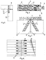
- the connecting means shown in FIG. 1 is an embodiment of a thin metal ash 1 according to the invention, which is equipped with anchor elements 2 of circular cross section and a tip on a bearing surface.
- the anchor elements 2 are designed so that they can be fixed in the surface of the gas concrete component by driving. This creates a mechanical form fit, which provides the connecting element with the ability to transmit forces parallel to the plate level.
- the anchor elements are designed such that, after they have been fixed in the gas concrete, they produce a local solidification of the penetrated concrete zone in that they produce a structural compaction directly on the anchor element by material displacement.
- this can only be achieved if the shape of the anchor element leads to material compression and the displacement volume is matched to the spacing of the anchor elements, so as not to cause splitting cracks in the rest of the gas concrete structure. Therefore, the volume of an anchor element must be matched to the pore volume of the gas concrete so that there is no destruction of the gas concrete in the selected distance of the anchor elements.
- the invention teaches in claim 1 with regard to the dimensions of the anchor elements to be observed and their spacing from one another.
- the basic principle of the subject matter of the invention is comparable to the construction of a pile foundation, where the pile heads are connected to one another by means of a rigid disk in such a way that shear forces in the disk plane produce jacket pressures of the piles in the ground.
- the structural compaction caused by the material displacement, just as in the subsoil, has a load-distributing meaning.
- the clamping of the pile heads in the load-distributing, integrating disc is no less important. On the one hand, the disc guides the claw heads when driving in, on the other hand, the clamping causes one Reduction in bending. For this reason, anchor elements that are butt-welded to a bracket are clamped in a higher straight line than claws formed by punching out of the bracket.
- Claw plates as they are known per se and are used in timber construction, can, under certain conditions, be quite suitable for taking on the task of the invention.
- the claws have to be integrated into the gas concrete for a sufficiently long time in order to achieve clamping in the gas concrete.
- Only short-integrating claws with low bending stiffness only have a low, proportional load absorption, because they are not clamped in the gas concrete and twist under the attacking load.
- the anchor elements 2 have a length which is at least 10 and a maximum of 20 times the lug thickness d. They have a cross section in the order of 1.5 d2 to 3 d2 and have a spacing density in the order of 10 d2 to 20 d2.
- the lug thickness d can be minimized to 1.5 mm when it is designed as a claw lug. Thicknesses greater than 5 mm will not be chosen for other versions either, since they require an inclusion in the surface of the gas concrete.
- FIG. 2 An example of another embodiment of the connecting element is shown in FIG. 2, in which the anchor elements 2 consist of claws 4 formed by stamping on the tab and formed on the tab.
- the claws inevitably have a square to rectangular cross-section, which naturally results in the higher bending stiffness over the longer cross-sectional side.
- the invention also provides for the installation of the claw tab 3 in the form where the broad side of the claws takes effect in the main direction of stress, as can be seen from the illustration in FIG. 5.
- a parallelogram-shaped tab is advantageous in individual cases.
- the tab shape shown in FIG. 2 proves to be very useful if a holder 5 is formed on a narrow side.
- the bracket 5 is inserted into a connecting part 11 and the tab is driven into the surface of the wall plate bearing joint.
- a positive connection between the wall and the concrete support is established by the positive engagement of the holder in the connecting part and the fixing of the tab in the wall component 12. This can be done both with claw tabs 3 with only one-sided arrangement of claws and with two-sided arrangement of claws, so that the lower and the overlying wall plate are held simultaneously in a joint.
- the tips of the claws are designed as a symmetrical roof edge. They are all oriented in the same direction in a row, but the orientation changes from row to row.
- the spacing area of the claws is characterized by a symmetrical rhombus that comes very close to the shape of a square. This makes the tab wider and the load transfer concentrated to a shorter length. In particularly stored cases, a short load introduction length may be desirable, but in general load introduction over a longer length is more important.
- a double claw tab can be produced by folding in the longitudinal or transverse direction, which then has claws on both bearing surfaces. Claws of a tab on both sides can also be molded on, as can be seen from FIGS. 4 and 5.
- the difference to the folded claw tab is that the claw density per unit area is lower than that of the folded one.
- connection device 6 is formed on a narrow side of this tab in the form of a toothed eyelet.
- Other designs of the connection device are also advantageous on a case-by-case basis, as can also be seen in FIG. 10 using the example of a fold.
- a tension member 8 can be connected, the end of which likewise has an eyelet-like connecting device in the dimensions which permits insertion into the toothed arrangement of FIG. 3.
- the connection of the tension member 8 with the claw lug 3 is simply accomplished in this case by means of a plug-in bolt which, with the appropriate design of the eyelet and the bolt with a self-tapping thread, can be fixed by screwing it into the eyelet.
- 4 shows an example of a claw tab 3 in which the punched claws 4 alternately emerge from the tab.
- the claws 4 of the underside are distributed in an oblique diamond shape, as the dashed line is intended to illustrate.
- the distance surface of a claw on the surface is represented by the dotted, oblique rhombus.
- the dotted, oblique rhombus also shows the distribution of the claws 4 on the underside.
- the tips of the claws are formed by inclined surfaces inclined on one side.
- the peculiarity of the design of these claws is that the inclination of the inclined surfaces of a longitudinal row is the same, while the orientation of the inclination of the longitudinal row increases Longitudinal row changes.
- the displaced material in the gas concrete structure is alternately distributed more to one or the other side of a claw 4, and a lateral run of the angled punch-out causes the desired effect that the punched out, which is initially straight, is transformed into a curved claw.
- a minimization of the claw distance to the side can be achieved, as a result of which the outer shape of the claw tab advantageously takes the form of an elongated rectangle.
- Connection devices 6 as shown by way of example in FIGS. 3 and 10, can also be implemented on several edges of the claw tabs. So it can be advantageous that the connection devices are arranged on two mutually perpendicular edges in order to be able to connect the tension members of the ring anchor to the claw plate in the two directions at a component corner.
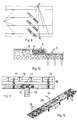
- a tab 15 is installed with a claw-free zone in the butt joints of the ceiling components 14 and the butt joints of the wall components 12 over the bed joint of the ceiling.
- the section through the ceiling outer wall support shows the ring anchor 8 in the cross-sectional center. Depending on the local conditions, it may be more advantageous to arrange the tab 15 near the outer wall surface.
- the shown use of the tab 15 as a "wall-ceiling connector" shows the universal use of the subject matter of the invention.
- FIG. 11 Designs of the tab 15 with two claw-free zones and their use can be seen in FIG. 11.
- the use of claw tabs 15 with a very large claw-free zone is shown in FIG. 8.
- the tab 15 spans the forehead joint of ceiling components 14 made of gas concrete and takes over the function of a bending reinforcement on the center support of the ceiling components when the pressure forces activated from the bending are transmitted to the forehead joint. If one provides, as the invention provides, the joint to the gas concrete with a suitable composite material, the moment can be distributed and the stress on the end anchorage reduced by the claws.
- FIG. 9 Another example of the useful use of the claw-free tab 15 is shown in FIG. 9.
- the longitudinal joints of ceiling components are with claw-free tabs 15, according to the shear stress Joint spanned at an angle of 45 ° to the joint and connected to each other.
- the claw-free tab 15 acts as a shear-securing connecting means which, according to the invention, ensures that the roof and ceiling components interact to form a statically effective pane.
- the shear forces can also be absorbed in the longitudinal butt joints of the roof and ceiling panels if claw plates 3 with claws on both sides are arranged.
- the installation of such elements presupposes, however, that devices are available which can be used on site to involve the panel to be connected, so that the claws 4 press evenly into the longitudinal butt joint.
- Anchoring by means of claw tabs 3 in the longitudinal joint, as well as with claw tabs 15 on the surface of ceiling panels, enable the production of a ceiling panel from gas concrete ceiling panels in a relatively simple, quick and efficient manner.
- the invention also provides, among other things, for the use of the connecting elements for anchoring ring anchors.
- a claw tab 3 is connected to a fold as a connection device 6, with a tension member 8 by double wedges 7, which allow tensioning of the tension member designed as a ring anchor.
- the tension member 8 itself can be designed as a claw tab at the other end or can in turn be connected to a connecting element according to the invention.
- the invention also provides for the use of claw tabs as an air layer anchor 13.
- An example of the formation of an air layer anchor for connecting a facing brickwork 16 with a gas concrete wall component 12 over an air gap 17 is shown in FIG. 11.
- FIG. 12 An exemplary embodiment of the air-layer anchor is shown isometrically in FIG. 12. It consists of a short, strip-shaped claw tab with a central part that has a bead 20 for longitudinal reinforcement and one that is integrated into the bed joints of the facing brickwork Extension with profiled punchings 19.
- the air layer anchor shown has claws 4 in the central part at a distance from the air gap thickness. It is designed in such a way that it transmits both tensile and compressive forces which act on the facing masonry 16 to the wall component made of gas concrete 12.
- the supports 21 in the center of the anchor have a distance which corresponds to the thickness of the air gap 17. As a rule, the standard size 5 cm is provided for this.
- the air layer anchor 13 thus also takes on the function of a spacer, which ensures the intended thickness of the air layer.
- the subject of the invention in the form of thin metal tabs, which have anchor elements that are easily fixed in the surface of gas concrete components, is a new type of connecting element that opens up new possibilities for building with gas concrete in its universal applicability. It creates the possibility of building a structure out of gas concrete without cement mortar or concrete, to a certain extent using the dry process, without waiting times. With the help of the new type of connection, gas concrete ceiling and roof panels can be produced, reinforced in the joints and designed so that they can be used to stiffen the entire structure, since their connection to wall panels can also be produced using the connecting elements according to the invention.
- Lugs with claw-free zones can be used as additional shear reinforcement for a ceiling slab, but also to cover a bending moment in the butt joint of ceiling slabs to reduce the deflection of the ceiling slab.
- the new connecting elements can be used with reactive resins to create an additional bending reinforcement on site, which can be covered by gas concrete by arrangement in the butt joints to meet the requirements of fire protection.
Landscapes
- Engineering & Computer Science (AREA)
- General Engineering & Computer Science (AREA)
- Mechanical Engineering (AREA)
- Joining Of Building Structures In Genera (AREA)
Claims (10)
- Liaison comprenant des pièces de construction en béton cellulaire, ainsi qu'une patte métallique munie d'éléments d'ancrage verrouillés à demeure, par concordance de formes, dans la surface des pièces de construction en béton cellulaire,
caractérisée par le fait- que la patte métallique coiffe le joint entre les pièces de construction en béton cellulaire,- que l'assemblage par conformation est établi par les éléments d'ancrage, qui sont enfoncés dans la surface de la pièce de construction en béton cellulaire,- que les éléments d'ancrage présentent une longueur comprise entre 10 et 20 fois l'épaisseur (d) de la patte,- que les éléments d'ancrage (2) sont de section transversale ronde, mesurant de l'ordre de 1,5 d² à 3 d²,- que l'élément d'ancrage (2) possède une densité d'espacement de l'ordre de 10 d² à 20 d²,- que les éléments d'ancrage (2) sont pourvus d'une pointe,- que la patte (1) comporte éventuellement, à l'une des extrémités étroites, un organe de retenue (5) ménagé solidairement, et peut par conséquent être reliée à d'autres pièces de construction,- que la patte (1, 3) possède éventuellement, sur ses bords, des dispositifs de rattachement (6) ménagés solidairement et/ou rapportés par soudage, et revêtant la forme d'agrafes repliées ou d'oeillets pouvant être munis d'une denture. - Liaison selon la revendication 1, caractérisée par le fait que les éléments d'ancrage (2) sont des griffes (4) ménagées solidairement à angle droit par poinçonnage à partir de la patte (3), et présentant une longueur d'au moins 15 d, le façonnage solidaire étant éventuellement exécuté sur les deux surfaces de contact.
- Liaison selon la revendication 2, caractérisée par le fait que les griffes (4) sont orientées, de préférence par le côté étroit, au besoin par le côté large, dans la direction d'effort principal.
- Liaison selon l'une des revendications 1 à 3, caractérisée par le fait que la surface de contact de la patte (1, 3) est dotée d'une couche durcissable du côté des éléments d'ancrage, et peut être solidarisée avec le béton cellulaire.
- Liaison selon l'une des revendications 1 à 4, caractérisée par le fait que la patte métallique consiste en un métal résistant à la corrosion.
- Liaison selon l'une des revendications 1 à 5, caractérisée par le fait que la patte (15) possède, au centre de l'étendue longitudinale, au moins une zone dépourvue d'éléments d'ancrage.
- Liaison selon l'une des revendications 1 à 5, caractérisée par le fait que la patte relie un élément de paroi en béton cellulaire à une structure portante, telle que des montants de soutien en béton armé ou en acier, en insérant l'organe de retenue (5), par concordance de formes, dans une partie de rattachement (11) qui est fermement ancrée dans la pièce de construction.
- Liaison selon l'une des revendications 1 à 6, caractérisée par le fait que la patte (15) coiffe le joint des pièces de construction en béton cellulaire selon en angle de 45°.
- Liaison selon l'une des revendications 1 à 5, caractérisée par le fait que la patte relie la pièce de construction en béton cellulaire à un organe de traction, par exemple à une ancre annulaire.
- Liaison selon l'une des revendications 1 à 6, caractérisée par le fait que la patte est réalisée sous la forme d'une ancre (13) pour vides sanitaires, enjambe un vide d'air (17), et relie une muraille en béton cellulaire à une coque de parement.
Priority Applications (1)
| Application Number | Priority Date | Filing Date | Title |
|---|---|---|---|
| AT88106900T ATE73884T1 (de) | 1987-04-30 | 1988-04-29 | Verbindung fuer bauteile aus gasbeton. |
Applications Claiming Priority (2)
| Application Number | Priority Date | Filing Date | Title |
|---|---|---|---|
| DE19873714537 DE3714537A1 (de) | 1987-04-30 | 1987-04-30 | Verbindungselement fuer bauteile aus gasbeton |
| DE3714537 | 1987-04-30 |
Publications (3)
| Publication Number | Publication Date |
|---|---|
| EP0289038A2 EP0289038A2 (fr) | 1988-11-02 |
| EP0289038A3 EP0289038A3 (en) | 1989-06-07 |
| EP0289038B1 true EP0289038B1 (fr) | 1992-03-18 |
Family
ID=6326638
Family Applications (1)
| Application Number | Title | Priority Date | Filing Date |
|---|---|---|---|
| EP88106900A Expired - Lifetime EP0289038B1 (fr) | 1987-04-30 | 1988-04-29 | Liaison pour piéces de construction en beton cellulaire |
Country Status (3)
| Country | Link |
|---|---|
| EP (1) | EP0289038B1 (fr) |
| AT (1) | ATE73884T1 (fr) |
| DE (1) | DE3714537A1 (fr) |
Families Citing this family (5)
| Publication number | Priority date | Publication date | Assignee | Title |
|---|---|---|---|---|
| AT397399B (de) * | 1989-08-17 | 1994-03-25 | Stracke Ing Markus | Baukonstruktionsteil |
| SE466807B (sv) * | 1990-01-23 | 1992-04-06 | Gunnebo Jernmanufaktur Ab | Faestdon |
| US5615524A (en) * | 1993-07-12 | 1997-04-01 | Costa, Sr.; Edward A. | Masthead and spreader bird roosting guard |
| DE4441681A1 (de) * | 1994-11-23 | 1996-05-30 | Teroson Gmbh | Verfahren zum Verbinden von Kunststoff-Formteilen |
| PL201221B1 (pl) * | 2001-03-28 | 2009-03-31 | Mirosław Kosiorek | Przestawna przegroda budowlana zwłaszcza przeciwpożarowa |
Family Cites Families (8)
| Publication number | Priority date | Publication date | Assignee | Title |
|---|---|---|---|---|
| LU33302A1 (fr) * | 1954-01-13 | |||
| FR1391693A (fr) * | 1963-05-13 | 1965-03-12 | Automated Building Components | Raccord métallique pour pièces de bois |
| GB1090373A (en) * | 1964-01-09 | 1967-11-08 | Beves And Company Ltd | Improvements in or relating to connector plates for joining timbers |
| GB1189801A (en) * | 1969-01-02 | 1970-04-29 | Standard Telephones Cables Ltd | Improvements in Fire Warning Cables. |
| DE2606666C2 (de) * | 1976-02-19 | 1982-03-18 | Greimbau-Lizenz-Gmbh, 3200 Hildesheim | Nagelplatte zum Verbinden von Holzbauteilen |
| DE7810267U1 (de) * | 1978-04-06 | 1978-11-09 | Butplate Ltd., Birmingham (Grossbritannien) | Befestigungselement zum verbinden von laenglichen rahmenhoelzern und rahmenstirnhoelzern zur bildung eines starren rahmens fuer ein tor, insbesondere gattertor |
| US4318652A (en) * | 1979-06-29 | 1982-03-09 | Truswal Systems Corporation | Connector plate |
| IT1208566B (it) * | 1985-08-05 | 1989-07-10 | Lucifero Srl | Procedimento e dispositivo per fissare elementi di supporto, di collegamento o di articolazione apannelli di polistirolo espanso. |
-
1987
- 1987-04-30 DE DE19873714537 patent/DE3714537A1/de not_active Ceased
-
1988
- 1988-04-29 EP EP88106900A patent/EP0289038B1/fr not_active Expired - Lifetime
- 1988-04-29 AT AT88106900T patent/ATE73884T1/de active
Also Published As
| Publication number | Publication date |
|---|---|
| EP0289038A3 (en) | 1989-06-07 |
| ATE73884T1 (de) | 1992-04-15 |
| DE3714537A1 (de) | 1988-11-17 |
| EP0289038A2 (fr) | 1988-11-02 |
Similar Documents
| Publication | Publication Date | Title |
|---|---|---|
| EP1097032B1 (fr) | Element en bois stratifie prefabrique | |
| DE3046790C2 (de) | Verbindung von Trägern mit einer durchgehenden Stütze und Verfahren zum Herstellen einer derartigen Verbindung | |
| WO2006122902A2 (fr) | Structure de mur pour batiment | |
| CH628107A5 (de) | Vorgespanntes deckenfeld, insbesondere zur herstellung von hochbaudecken, sowie verfahren zur herstellung von deckenfeldern. | |
| EP0164330B1 (fr) | Plancher en béton armé | |
| EP0289038B1 (fr) | Liaison pour piéces de construction en beton cellulaire | |
| DE3124686A1 (de) | Fassadenverkleidungssystem fuer die aussenfassade von gebaeuden | |
| EP0045978B1 (fr) | Barre de support à ancrer dans la construction de support pour une façade consistant en plaques de pierre de taille, de béton ou de céramique | |
| DE202023101973U1 (de) | Vorgefertigte Verbundplatte mit einer Verbindungsstruktur eng nebeneinander angeordneter und miteinander zusammengesetzter unregelmäßig geformter Bewehrungsstäbe | |
| DE4323011A1 (de) | Stahlbetonfertigbauteil und damit errichtetes Gebäude | |
| DE2700089A1 (de) | Kraftschluessige verbindung von bauelementen | |
| EP3919702A1 (fr) | Composant composite bois-béton et procédé de formation d'un composant composite bois-béton | |
| DE3529619A1 (de) | Betonplatte mit waermedaemmung fuer den hoch- und tiefbau und verfahren zu ihrer herstellung | |
| EP2196588B1 (fr) | Système de revêtement | |
| DE1509588A1 (de) | Platte zur Verkleidung von und Befestigung an Fassadenwaenden | |
| CH663813A5 (en) | Building cladding material securing device - consists of bracket with slotted hole for anchorage bolt permitting vertical and horizontal adjustment | |
| DE4322741C2 (de) | Maueranschlußanker | |
| DE4101133C2 (de) | Verfahren zur Befestigung von Bahnen an Holzwolle-Leichtbauplatten | |
| DE19636828C2 (de) | Verfahren und Bauelement zur Herstellung von Bauwerksteilen | |
| AT352958B (de) | Vorgefertigtes deckenelement | |
| AT380505B (de) | Vorgefertigtes schalungselement | |
| DE3105994C2 (de) | Schalungsplatte | |
| DD255564A1 (de) | Verfahren und vorrichtung zur verankerung und vertikal-fugenausbildung von montagewaenden | |
| DE911906C (de) | Verfahren zur Herstellung von gewichtsersparenden Zwischenbauteilen fuer Massivdecken | |
| DE2750931C2 (fr) |
Legal Events
| Date | Code | Title | Description |
|---|---|---|---|
| PUAI | Public reference made under article 153(3) epc to a published international application that has entered the european phase |
Free format text: ORIGINAL CODE: 0009012 |
|
| AK | Designated contracting states |
Kind code of ref document: A2 Designated state(s): AT CH FR GB LI NL |
|
| 17P | Request for examination filed |
Effective date: 19890213 |
|
| PUAL | Search report despatched |
Free format text: ORIGINAL CODE: 0009013 |
|
| AK | Designated contracting states |
Kind code of ref document: A3 Designated state(s): AT CH FR GB LI NL |
|
| 17Q | First examination report despatched |
Effective date: 19900503 |
|
| GRAA | (expected) grant |
Free format text: ORIGINAL CODE: 0009210 |
|
| AK | Designated contracting states |
Kind code of ref document: B1 Designated state(s): AT CH FR GB LI NL |
|
| REF | Corresponds to: |
Ref document number: 73884 Country of ref document: AT Date of ref document: 19920415 Kind code of ref document: T |
|
| GBT | Gb: translation of ep patent filed (gb section 77(6)(a)/1977) | ||
| ET | Fr: translation filed | ||
| PLBE | No opposition filed within time limit |
Free format text: ORIGINAL CODE: 0009261 |
|
| STAA | Information on the status of an ep patent application or granted ep patent |
Free format text: STATUS: NO OPPOSITION FILED WITHIN TIME LIMIT |
|
| 26N | No opposition filed | ||
| PGFP | Annual fee paid to national office [announced via postgrant information from national office to epo] |
Ref country code: NL Payment date: 19940430 Year of fee payment: 7 |
|
| PGFP | Annual fee paid to national office [announced via postgrant information from national office to epo] |
Ref country code: GB Payment date: 19940526 Year of fee payment: 7 |
|
| PGFP | Annual fee paid to national office [announced via postgrant information from national office to epo] |
Ref country code: AT Payment date: 19940714 Year of fee payment: 7 |
|
| PGFP | Annual fee paid to national office [announced via postgrant information from national office to epo] |
Ref country code: CH Payment date: 19950422 Year of fee payment: 8 |
|
| PG25 | Lapsed in a contracting state [announced via postgrant information from national office to epo] |
Ref country code: GB Effective date: 19950429 Ref country code: AT Effective date: 19950429 |
|
| PG25 | Lapsed in a contracting state [announced via postgrant information from national office to epo] |
Ref country code: NL Effective date: 19951101 |
|
| NLV4 | Nl: lapsed or anulled due to non-payment of the annual fee |
Effective date: 19951101 |
|
| GBPC | Gb: european patent ceased through non-payment of renewal fee |
Effective date: 19950429 |
|
| PGFP | Annual fee paid to national office [announced via postgrant information from national office to epo] |
Ref country code: FR Payment date: 19960425 Year of fee payment: 9 |
|
| PG25 | Lapsed in a contracting state [announced via postgrant information from national office to epo] |
Ref country code: LI Effective date: 19960430 Ref country code: CH Effective date: 19960430 |
|
| REG | Reference to a national code |
Ref country code: CH Ref legal event code: PL |
|
| PG25 | Lapsed in a contracting state [announced via postgrant information from national office to epo] |
Ref country code: FR Free format text: LAPSE BECAUSE OF NON-PAYMENT OF DUE FEES Effective date: 19971231 |
|
| REG | Reference to a national code |
Ref country code: FR Ref legal event code: ST |