EP0289050A2 - Verfahren zum Verschachteln von Datenfolgen - Google Patents
Verfahren zum Verschachteln von Datenfolgen Download PDFInfo
- Publication number
- EP0289050A2 EP0289050A2 EP88106922A EP88106922A EP0289050A2 EP 0289050 A2 EP0289050 A2 EP 0289050A2 EP 88106922 A EP88106922 A EP 88106922A EP 88106922 A EP88106922 A EP 88106922A EP 0289050 A2 EP0289050 A2 EP 0289050A2
- Authority
- EP
- European Patent Office
- Prior art keywords
- interleave
- data
- delay
- error correction
- sample
- Prior art date
- Legal status (The legal status is an assumption and is not a legal conclusion. Google has not performed a legal analysis and makes no representation as to the accuracy of the status listed.)
- Granted
Links
Images


Classifications
-
- G—PHYSICS
- G11—INFORMATION STORAGE
- G11B—INFORMATION STORAGE BASED ON RELATIVE MOVEMENT BETWEEN RECORD CARRIER AND TRANSDUCER
- G11B21/00—Head arrangements not specific to the method of recording or reproducing
- G11B21/02—Driving or moving of heads
- G11B21/10—Track finding or aligning by moving the head ; Provisions for maintaining alignment of the head relative to the track during transducing operation, i.e. track following
-
- H—ELECTRICITY
- H04—ELECTRIC COMMUNICATION TECHNIQUE
- H04N—PICTORIAL COMMUNICATION, e.g. TELEVISION
- H04N9/00—Details of colour television systems
- H04N9/79—Processing of colour television signals in connection with recording
- H04N9/80—Transformation of the television signal for recording, e.g. modulation, frequency changing; Inverse transformation for playback
- H04N9/802—Transformation of the television signal for recording, e.g. modulation, frequency changing; Inverse transformation for playback involving processing of the sound signal
-
- G—PHYSICS
- G11—INFORMATION STORAGE
- G11B—INFORMATION STORAGE BASED ON RELATIVE MOVEMENT BETWEEN RECORD CARRIER AND TRANSDUCER
- G11B20/00—Signal processing not specific to the method of recording or reproducing; Circuits therefor
- G11B20/10—Digital recording or reproducing
- G11B20/18—Error detection or correction; Testing, e.g. of drop-outs
- G11B20/1806—Pulse code modulation systems for audio signals
- G11B20/1809—Pulse code modulation systems for audio signals by interleaving
-
- H—ELECTRICITY
- H04—ELECTRIC COMMUNICATION TECHNIQUE
- H04N—PICTORIAL COMMUNICATION, e.g. TELEVISION
- H04N9/00—Details of colour television systems
- H04N9/79—Processing of colour television signals in connection with recording
- H04N9/7921—Processing of colour television signals in connection with recording for more than one processing mode
- H04N9/7925—Processing of colour television signals in connection with recording for more than one processing mode for more than one standard
Definitions
- the present invention relates to a digital audio signal interleave sequence method for recording and reproducing digital audio signals on and from a video tape simultaneously with video signals using rotary heads.
- PCM pulse code modulation
- VTR video tape recorder
- FM frequency modulation
- a drop-out in reproduced data i.e., a missing data phenomenon due to defects on the medium or some other reasons may occur.
- error correction codes or so-called redundancy data are added to original digital audio data to be recorded. Since a drop-out due to burst errors is quite above the capacity of error correction codes alone, a data dispersion method called an interleave has been adopted wherein burst errors are converted into random errors.
- Interleave methods for converting burst errors into random errors are mainly divided into two types: a helical type interleave which adopts simple delays as used in CDs, and a block completed type interleave as used in R-DATs.
- VTRs for business use now adopt the block completed type interleave method wherein independent tracks are provided for video and sound signals, and the sound signals are subjected to time compression for recording and reproducing (e.g., refer to S. Tujii et. al.; "Digital Audio Recording in M-II Format VTR" SMPTE 20th Television Conference No. 24, pp. 187 to 200, February 1986).
- the helical type interleave method is complicated in processing signals due to its non-completed nature, it can process signals within a time corresponding to a so-called "interleave depth".
- the helical type interleave method can advantageously process signals within half the time required by the former, or less.
- the helical type interleave method has been applied to CDs for example. Contrary to the application to discs, the helical type interleave method has been found not always satisfactory in signal processing and error correction ability if it is applied to rotary head type VTRs for recording digital sound signals.
- the interleave sequence method of this invention comprises the steps of: dividing an inputted digital audio signal into process units having an even number of samples per channel, separating one sample into an upper symbol and a lower symbol, synchronizing the divided digital audio signal with a video signal by inserting dummy data in the divided digital audio signal at a video field period, and classifying the synchronized digital audio signal into an odd series and an even series in the time sequential order of sampling (scrambling process); giving a predetermined delay between the classified odd and even series (an offset delay process); delaying both the predetermined time delayed series such that a different delay time is given to each sample data (main interleave process); generating a first error correction code C2 at the stage before or after the main interleave process, based on both the predetermined time delayed series (a C2 encode process); subjecting the generated first error correction code C2 to the same main interleave process, and delaying the data subjected to the main interleave process such that only ones of the upper symbols and
- a digital audio signal is synchronized with a video signal at each video field period, the upper and lower symbols of respective sample data are disposed on a video tape in conjugate relation to each other, the first or second error correction code series are made the same with respect to the upper and lower symbols of each sample data, and the superposition of the first and second error correction code series to the upper and lower symbols of each sample data is avoided, to thereby enable high error correction ability and short process delay time.
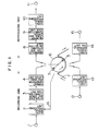
- FIG. 1 The structure of a VTR having a digital audio recording function embodying the interleave method according to the present invention is shown in Fig. 1.
- reference numeral 1 represents an input terminal for a digital audio signal
- 2 an audio signal processing unit
- 3 an interleave and error correction code (hereinafter abbreviated as ECC) unit
- 4 a format generation and modulation unit
- 5 a rotary head
- 6 a rotary cylinder
- 7 a video tape
- 8 a demodulation and synchro detection unit
- 9 a de-interleave and ECC unit
- 10 an audio signal processing unit
- 11 an output terminal for a digital audio signal
- Reference numeral 12 represents a video signal input terminal, 13 a video signal recording unit, 14 a video signal reproducing unit, and 15 a video signal output terminal, all of which are similar in construction and operation to those conventional.
- a signal to be inputted to the digital audio signal input terminal 1 is an audio signal already digitalized by an A/D converter.
- a stereo signal with right (R) and left (L) two channels at a sample frequency 48 kHz and 16 bit linear quantization is considered in this embodiment by way of example.
- a digital audio signal inputted to the audio signal processing unit 2 is divided into process units composed of time sequentially consecutive 6 sample data per channel, similar to those in CDs except that the signal is separately recorded by rotary heads so that the signal is necessary to be subjected to a synchronization process with a video signal.
- the digital audio signal thus can be synchronized with the video signal by selectively recording both types of fields while monitoring the revolution period of the rotary cylinder.
- the optimum field structure for different recording conditions such as field frequency, sample frequency, channel number or the like may be determined readily in accordance with the same design criterion.
- an ID bit is recorded in a header to be described later by performing an interleave process in a similar manner as of digital audio data.
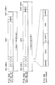
- a digital audio signal is divided into process units composed of 6 samples per a channel by the audio signal processing unit 1 shown in Fig. 1, filled in with dummy data synchronized with a video signal at each field, and inputted to the interleave and ECC unit 3 shown in Fig. 1.
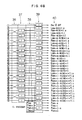
- reference numeral 21 represents an input terminal for digital audio data, 22 a scramble processing unit, 23 an offset delay processing unit, 24 a C2 encode processing unit, 25 a main interleave processing unit, 26 a C1 interleave processing unit, 27 a C1 encode processing unit, 28 a C1 de-interleave processing unit and 29 an output terminal for digital audio data.
- Digital audio data applied to the input terminal 21 are divided into one-block process units each composed of 6 samples for L channel and 6 samples for R channel. Each process unit is then separated into even and odd series in the time sequential order by the scramble processing unit 22. A predetermined delay is given between both the series by the offset delay processing unit 23 to thereby improve an interpolation function during the reproducing. Thereafter, a first error correction code C2 is generated at the C2 encode processing unit 24, based on the data of both the series subjected to the scramble process and the offset delay process. The data subjected to the scramble process and offset delay process and the first error correction code C2 are delayed by the main interleave processing unit 25 such that a different linear delay is given to each sample data.
- the lower symbols of respective sample data are delayed by a unit (one block) time by the C1 interleave processing unit 26 whereby a second error correction code C1 is generated by the C1 encode processing unit 27 and added to the data delayed by the unit time by the C1 interleave processing unit 26.
- the upper symbols, opposite to those processed by the C1 interleave processing unit 26, of the obtained sample data are delayed by the same unit time by the C1 de-interleave processing unit 28, the resultant data being outputted from the digital audio data output terminal 29.
- the data added with the first and second error correction codes and subjected to the interleave processes are then inputted, as the data constituting one-block record format, to the format generation and modulation unit 4 shown in Fig. 1.
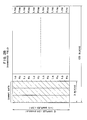
- one-block data are added with a header including a synchronous signal, the ID bit and other necessary information.
- a 525 - 60 field system i.e., NTSC system VTR and a 625 line - 50 filed system, i.e., PAL or SECAM system VTR
- one-field data are constructed of 135 blocks and 162 blocks, respectively, with a pre-amble and a post-amble added to the start and end of the field for keeping off unstable durations before and after switching rotary heads.
- the digital audio signal thus processed is then multiple-recorded with a video signal on a video tape.
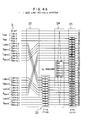
- the delay amount is the same for both the upper and lower symbols of each sample data at the main interleave processing unit 25 shown in Fig. 4, and the C1 interleave processing unit 26 and the C1 de-interleave processing unit 28 are provided after and before the C1 encode processing unit 27. Therefore, the first error correction code C2 can be made the same with respect to the upper and lower symbols of each sample data, the upper and lower symbols can be recorded on a magnetic tape in conjugate relation to each other, and the first and second error correction codes can be arranged without any superposition. It becomes accordingly possible to realize a digital audio recording and reproducing apparatus having high error detection and correction ability while retaining the advantage of the helical type interleave, i.e., short delay in processing.
- the first and second error correction codes used in the above embodiment are not specifically identified, but they may be a Reed-Solomon code or any other code.
- As the code length 6 symbols and 4 symbols have been used for the first and second error correction codes C2 and C1, respectively. However, the code length may be determined optionally in accordance with the desired error correction ability.
- the delay amount set by the offset delay processing unit 23, main interleave processing unit 25, C1 interleave processing unit and C1 de-interleave processing unit 28 has been determined such that the total delay time in processing becomes about one field in each television system, the delay amount may be determined optionally in accordance with the desired error correction ability.
- the object of the interleave method of the above embodiment is to record the upper and lower symbols on a magnetic tape in conjugate relation to each other and to make the first error correction code C2 series the same with respect to the upper and lower symbols of each sample data.
- the upper and lower symbols are not necessary by all means to have the same error correction code C2, but they may have otherwise the same error correction code C1.
- This modification is shown in Figs. 6A and 6B wherein generating a first error correction code C2 at the C2 encode processing unit 34 is carried out at the middle of a main interleave processing unit 35 so that the first error correction code series displaces from the upper and lower symbol series.
- the upper and lower symbol series have the same second error correction code C1.
- the positional arrangement of the upper and lower symbols on a magnetic tape is not in conjugate relation to each other, but it is in adjacent relation separated by one symbol.
- This modification can also have the same high error correction ability as the above embodiment.
- the detailed structure of the de-interleave and ECC unit of the modification is shown in Figs. 7A and 7B.
Landscapes
- Engineering & Computer Science (AREA)
- Signal Processing (AREA)
- Multimedia (AREA)
- Signal Processing For Digital Recording And Reproducing (AREA)
- Error Detection And Correction (AREA)
Applications Claiming Priority (2)
| Application Number | Priority Date | Filing Date | Title |
|---|---|---|---|
| JP62106373A JPS63274222A (ja) | 1987-05-01 | 1987-05-01 | インタ−リ−ブ方法 |
| JP106373/87 | 1987-05-01 |
Publications (3)
| Publication Number | Publication Date |
|---|---|
| EP0289050A2 true EP0289050A2 (de) | 1988-11-02 |
| EP0289050A3 EP0289050A3 (en) | 1989-12-13 |
| EP0289050B1 EP0289050B1 (de) | 1993-01-07 |
Family
ID=14431918
Family Applications (1)
| Application Number | Title | Priority Date | Filing Date |
|---|---|---|---|
| EP88106922A Expired - Lifetime EP0289050B1 (de) | 1987-05-01 | 1988-04-29 | Verfahren zum Verschachteln von Datenfolgen |
Country Status (4)
| Country | Link |
|---|---|
| US (1) | US4852102A (de) |
| EP (1) | EP0289050B1 (de) |
| JP (1) | JPS63274222A (de) |
| KR (1) | KR920005272B1 (de) |
Cited By (2)
| Publication number | Priority date | Publication date | Assignee | Title |
|---|---|---|---|---|
| EP0334580A3 (de) * | 1988-03-21 | 1994-01-12 | Sony Corporation | System und Verfahren zur Durchführung der Fehlerkorrektur von Audiosignalen auf einem Standbild-Videoformatband |
| EP0552979A3 (en) * | 1992-01-23 | 1994-03-02 | Samsung Electronics Co Ltd | Apparatus and method for de-interleaving data |
Families Citing this family (29)
| Publication number | Priority date | Publication date | Assignee | Title |
|---|---|---|---|---|
| JP2867383B2 (ja) * | 1988-03-09 | 1999-03-08 | キヤノン株式会社 | 映像信号記録方法 |
| US5070503A (en) * | 1988-03-09 | 1991-12-03 | Canon Kabushiki Kaisha | Digital information transmitting and receiving system |
| JP2661206B2 (ja) * | 1988-10-31 | 1997-10-08 | キヤノン株式会社 | 映像信号記録装置 |
| FR2639781B1 (fr) * | 1988-11-25 | 1991-01-04 | Alcatel Thomson Faisceaux | Procede d'entrelacement pour dispositif de transmission numerique |
| JPH02192077A (ja) * | 1989-01-19 | 1990-07-27 | Sharp Corp | データ記録/再生装置 |
| US4993029A (en) * | 1989-03-13 | 1991-02-12 | International Business Machines Corporation | Method and apparatus for randomizing data in a direct access storage device |
| JP2832024B2 (ja) * | 1989-03-18 | 1998-12-02 | キヤノン株式会社 | 符号伝送方法 |
| US5109385A (en) * | 1989-04-27 | 1992-04-28 | International Business Machines Corporation | Enhanced data formats and machine operations for enabling error correction |
| US5111463A (en) * | 1989-11-09 | 1992-05-05 | Exabyte Corporation | Error correction method and apparatus |
| KR950001439B1 (ko) * | 1990-04-30 | 1995-02-24 | 삼성전자주식회사 | 오류정정부호화장치 |
| KR950009383B1 (ko) * | 1990-06-29 | 1995-08-21 | 마쯔시다 덴기 산교 가부시기가이샤 | 디지틀음성신호기록방법 |
| NL9100218A (nl) * | 1991-02-07 | 1992-09-01 | Philips Nv | Encodeer/decodeer-schakeling, alsmede digitaal video-systeem voorzien van de schakeling. |
| US5263030A (en) * | 1991-02-13 | 1993-11-16 | Digital Equipment Corporation | Method and apparatus for encoding data for storage on magnetic tape |
| US5504759A (en) * | 1991-07-11 | 1996-04-02 | Sony Corporation | Digital signal recording and/or reproducing apparatus using a common processing device for digital signals having different data configurations |
| US5325370A (en) * | 1991-11-12 | 1994-06-28 | Storage Technology Corporation | Method and apparatus for recording data on magnetic tape media |
| US5392299A (en) * | 1992-01-15 | 1995-02-21 | E-Systems, Inc. | Triple orthogonally interleaed error correction system |
| JP3213387B2 (ja) * | 1992-06-29 | 2001-10-02 | キヤノン株式会社 | 画像符号化方法及び画像復号化方法 |
| US5424881A (en) | 1993-02-01 | 1995-06-13 | Cirrus Logic, Inc. | Synchronous read channel |
| US5596604A (en) * | 1993-08-17 | 1997-01-21 | Amati Communications Corporation | Multicarrier modulation transmission system with variable delay |
| BR9505853A (pt) * | 1994-03-01 | 1996-02-21 | Sony Corp | Processo e aparelho de codificação e de decodificação de sinal digital e meio de registro de sinal digital |
| WO1996020474A2 (en) * | 1994-12-23 | 1996-07-04 | Philips Electronics N.V. | A method and device for use with helical scan data recording by implementing a reed-solomon product code, a unitary medium comprising such data, and a cassette comprising such medium |
| JPH10145238A (ja) * | 1996-11-13 | 1998-05-29 | Canon Inc | 誤り訂正装置及び方法 |
| US6192503B1 (en) * | 1997-08-14 | 2001-02-20 | Ericsson Inc. | Communications system and methods employing selective recursive decording |
| KR19990079604A (ko) * | 1998-04-07 | 1999-11-05 | 구자홍 | 심볼 디인터리빙 장치 |
| PL339309A1 (en) * | 1998-04-29 | 2000-12-04 | Koninkl Philips Electronics Nv | Method of as well as apparatus and carrier for encoding a multiple-word information |
| KR100521937B1 (ko) * | 2000-02-11 | 2005-10-13 | 엘지전자 주식회사 | 재기록 가능 기록매체에의 오디오 데이터 기록방법 |
| US7188298B2 (en) | 2001-03-14 | 2007-03-06 | Matsushita Electric Industrial Co., Ltd. | Error correction encoding and decoding methods and apparatuses for DVI audio data |
| JP2008301393A (ja) * | 2007-06-04 | 2008-12-11 | Funai Electric Co Ltd | 画像処理装置 |
| US9191686B2 (en) | 2011-07-22 | 2015-11-17 | Honeywell International Inc. | System and method of implementing synchronized audio and video streaming |
Family Cites Families (9)
| Publication number | Priority date | Publication date | Assignee | Title |
|---|---|---|---|---|
| JPS574629A (en) * | 1980-05-21 | 1982-01-11 | Sony Corp | Data transmitting method capable of correction of error |
| JPS5753806A (en) * | 1980-09-16 | 1982-03-31 | Toshiba Corp | Processor of digital signal |
| WO1982003719A1 (fr) * | 1981-04-16 | 1982-10-28 | Odaka Kentaro | Procede de codage de correction d'erreurs |
| JPH07118159B2 (ja) * | 1982-12-06 | 1995-12-18 | ソニー株式会社 | Pcm信号記録方法 |
| JPS6029073A (ja) * | 1983-06-17 | 1985-02-14 | Hitachi Ltd | ディジタル信号構成方式 |
| US4559625A (en) * | 1983-07-28 | 1985-12-17 | Cyclotomics, Inc. | Interleavers for digital communications |
| EP0156440B1 (de) * | 1984-03-24 | 1990-01-24 | Koninklijke Philips Electronics N.V. | Verfahren zur Informationsübertragung mit Fehlerkorrektur für Datenworte, ein Fehlerkorrektur-Dekodierverfahren für solche Datenworte, eine Anordnung zur Informationsübertragung zur Verwendung mit dem Verfahren, ein Gerät für Informationsdekodierung zur Verwendung mit dem Verfahren und eine Anordnung zur Verwendung mit solchem Gerät |
| FR2583240B1 (fr) * | 1985-06-05 | 1994-02-04 | France Telediffusion | Procede de transmission en blocs de mots d'information numerique |
| JPS63187469A (ja) * | 1987-01-30 | 1988-08-03 | Hitachi Ltd | 回転ヘツド形記録再生装置 |
-
1987
- 1987-05-01 JP JP62106373A patent/JPS63274222A/ja active Pending
-
1988
- 1988-04-28 US US07/187,315 patent/US4852102A/en not_active Expired - Lifetime
- 1988-04-29 EP EP88106922A patent/EP0289050B1/de not_active Expired - Lifetime
- 1988-04-29 KR KR1019880004917A patent/KR920005272B1/ko not_active Expired
Cited By (2)
| Publication number | Priority date | Publication date | Assignee | Title |
|---|---|---|---|---|
| EP0334580A3 (de) * | 1988-03-21 | 1994-01-12 | Sony Corporation | System und Verfahren zur Durchführung der Fehlerkorrektur von Audiosignalen auf einem Standbild-Videoformatband |
| EP0552979A3 (en) * | 1992-01-23 | 1994-03-02 | Samsung Electronics Co Ltd | Apparatus and method for de-interleaving data |
Also Published As
| Publication number | Publication date |
|---|---|
| KR920005272B1 (ko) | 1992-06-29 |
| JPS63274222A (ja) | 1988-11-11 |
| KR880014550A (ko) | 1988-12-24 |
| EP0289050A3 (en) | 1989-12-13 |
| US4852102A (en) | 1989-07-25 |
| EP0289050B1 (de) | 1993-01-07 |
Similar Documents
| Publication | Publication Date | Title |
|---|---|---|
| EP0289050B1 (de) | Verfahren zum Verschachteln von Datenfolgen | |
| JP2638091B2 (ja) | データ伝送方法 | |
| US4238852A (en) | Error correcting system | |
| JP3237152B2 (ja) | ディジタル情報信号の記録装置 | |
| EP0303450B2 (de) | Digital-Signal-Übertragungseinrichtung | |
| JP3377194B2 (ja) | 磁気記録担体上のトラックの開始部にクロックのロック用コード語を記録する方法及び記録担体 | |
| GB2076251A (en) | Digitized video and audio data recording and/or reproducing apparatuses | |
| US4920424A (en) | Method of recording and reproducing multi-channel information on and from recording medium | |
| JPH07111815B2 (ja) | デイジタル信号記録方式 | |
| US6370324B1 (en) | Digital information recorder/reproducer with ECC encoding of compressed signal and selective bypass of ECC encoding | |
| EP0595628B1 (de) | Magnetisches Aufnahme- und/oder Wiedergabegerät | |
| US5355132A (en) | Method for transmitting digital data | |
| US4181817A (en) | High bit rate digital data signal transmission system | |
| JPS6123590B2 (de) | ||
| EP0366402A2 (de) | Verfahren zur Aufzeichnung/Wiedergabe eines digitalen Audiosignals und mitgehende Einrichtung | |
| JP2579620B2 (ja) | 記録再生方法及び記録装置、再生装置 | |
| JP2675085B2 (ja) | 回転ヘッド形pcmレコーダの記録再生方法 | |
| JPH0644376B2 (ja) | 記録再生方法及び装置 | |
| JP2702509B2 (ja) | 映像と音声の再生装置 | |
| US6269219B1 (en) | Recording four channels of digital audio data on two channels of a magnetic tape | |
| JPH0377564B2 (de) | ||
| JPS63102076A (ja) | デイジタル信号記録装置 | |
| JPS6117058B2 (de) | ||
| JPS62239487A (ja) | デイジタルオ−デイオ信号の記録装置 | |
| JPS60224107A (ja) | デイジタルオ−デイオ信号記録再生装置 |
Legal Events
| Date | Code | Title | Description |
|---|---|---|---|
| PUAI | Public reference made under article 153(3) epc to a published international application that has entered the european phase |
Free format text: ORIGINAL CODE: 0009012 |
|
| AK | Designated contracting states |
Kind code of ref document: A2 Designated state(s): DE FR GB NL |
|
| PUAL | Search report despatched |
Free format text: ORIGINAL CODE: 0009013 |
|
| AK | Designated contracting states |
Kind code of ref document: A3 Designated state(s): DE FR GB NL |
|
| 17P | Request for examination filed |
Effective date: 19900131 |
|
| 17Q | First examination report despatched |
Effective date: 19910722 |
|
| GRAA | (expected) grant |
Free format text: ORIGINAL CODE: 0009210 |
|
| AK | Designated contracting states |
Kind code of ref document: B1 Designated state(s): FR NL |
|
| ET | Fr: translation filed | ||
| PLBE | No opposition filed within time limit |
Free format text: ORIGINAL CODE: 0009261 |
|
| STAA | Information on the status of an ep patent application or granted ep patent |
Free format text: STATUS: NO OPPOSITION FILED WITHIN TIME LIMIT |
|
| 26N | No opposition filed | ||
| PGFP | Annual fee paid to national office [announced via postgrant information from national office to epo] |
Ref country code: FR Payment date: 19970409 Year of fee payment: 10 |
|
| PG25 | Lapsed in a contracting state [announced via postgrant information from national office to epo] |
Ref country code: FR Free format text: THE PATENT HAS BEEN ANNULLED BY A DECISION OF A NATIONAL AUTHORITY Effective date: 19980430 |
|
| REG | Reference to a national code |
Ref country code: FR Ref legal event code: ST |
|
| PGFP | Annual fee paid to national office [announced via postgrant information from national office to epo] |
Ref country code: NL Payment date: 20010430 Year of fee payment: 14 |
|
| PG25 | Lapsed in a contracting state [announced via postgrant information from national office to epo] |
Ref country code: NL Free format text: LAPSE BECAUSE OF NON-PAYMENT OF DUE FEES Effective date: 20021101 |
|
| NLV4 | Nl: lapsed or anulled due to non-payment of the annual fee |
Effective date: 20021101 |