EP0289106A2 - Joints pour tête de puits - Google Patents
Joints pour tête de puits Download PDFInfo
- Publication number
- EP0289106A2 EP0289106A2 EP88300170A EP88300170A EP0289106A2 EP 0289106 A2 EP0289106 A2 EP 0289106A2 EP 88300170 A EP88300170 A EP 88300170A EP 88300170 A EP88300170 A EP 88300170A EP 0289106 A2 EP0289106 A2 EP 0289106A2
- Authority
- EP
- European Patent Office
- Prior art keywords
- annular
- wellhead
- sealing
- seal
- lips
- Prior art date
- Legal status (The legal status is an assumption and is not a legal conclusion. Google has not performed a legal analysis and makes no representation as to the accuracy of the status listed.)
- Granted
Links
Images


Classifications
-
- F—MECHANICAL ENGINEERING; LIGHTING; HEATING; WEAPONS; BLASTING
- F16—ENGINEERING ELEMENTS AND UNITS; GENERAL MEASURES FOR PRODUCING AND MAINTAINING EFFECTIVE FUNCTIONING OF MACHINES OR INSTALLATIONS; THERMAL INSULATION IN GENERAL
- F16J—PISTONS; CYLINDERS; SEALINGS
- F16J15/00—Sealings
- F16J15/46—Sealings with packing ring expanded or pressed into place by fluid pressure, e.g. inflatable packings
- F16J15/48—Sealings with packing ring expanded or pressed into place by fluid pressure, e.g. inflatable packings influenced by the pressure within the member to be sealed
-
- E—FIXED CONSTRUCTIONS
- E21—EARTH OR ROCK DRILLING; MINING
- E21B—EARTH OR ROCK DRILLING; OBTAINING OIL, GAS, WATER, SOLUBLE OR MELTABLE MATERIALS OR A SLURRY OF MINERALS FROM WELLS
- E21B33/00—Sealing or packing boreholes or wells
- E21B33/02—Surface sealing or packing
- E21B33/03—Well heads; Setting-up thereof
- E21B33/04—Casing heads; Suspending casings or tubings in well heads
-
- E—FIXED CONSTRUCTIONS
- E21—EARTH OR ROCK DRILLING; MINING
- E21B—EARTH OR ROCK DRILLING; OBTAINING OIL, GAS, WATER, SOLUBLE OR MELTABLE MATERIALS OR A SLURRY OF MINERALS FROM WELLS
- E21B2200/00—Special features related to earth drilling for obtaining oil, gas or water
- E21B2200/01—Sealings characterised by their shape
Definitions
- Wellhead seals of the prior art have involved the use of wedging action to spread sealing lips into sealing engagement with the interior of a wellhead housing and the exterior of a hanger, with a lip open to the pressure on its interior but not on its exterior or sealing side so that the pressure assists in urging the lip into a tight metal to metal sealing engagement.
- Other methods of energizing the seals have been employed to provide a radial force on the seal to urge it into tight sealing engagement with the cylindrical surface against which it is to seal.
- U. S. Patent No. 4,595,053 discloses an annular seal in which the seal is cup-shaped in section and is provided with an annular wedge which is received within the opening in the cup seal to force the lips of the cup seal outward and inward into tight sealing engagement with the interior of the housing and the exterior of the hanger.
- the sealing surfaces of the housing and hanger are provided with wickers which provide a series of threads for sealing.
- the present invention relates to an improved wellhead seal for sealing between spaced apart tubular members in a wellhead.
- Such seal is a metal seal with sealing lips which are assisted in their sealing engagement with the sealing surfaces on at least one of the sealing surfaces on the tubular members by an annular space behind one of the sealing surfaces which space is exposed to the pressure between the two members.
- the annular space creates an annular rim which is pressure energized toward the seal to ensure a positive metal-to-metal seal across the annulus between the tubular wellhead members.
- An object of the present invention is to provide an improved seal across the annulus between two spaced apart tubular wellhead members in which at least one of the sealing surfaces is pressure energized.
- Another object is to provide an improved wellhead annulus seal which is pressure energized by the pressure against which it is sealing both on the seal lips and on at least one of the sealing surfaces of the tubular members.
- a further object is to provide an improve wellhead annulus seal between the wellhead housing and a hanger in which the metal-to-metal seal is subjected to multiple pressure energization.
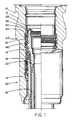
- Wellhead housing 12 includes internal downwardly tapering shoulder 14 on which first hanger 16 in landed and second hanger 18 is landed on upper tapered shoulder 19 on hanger 16.
- the landing and supporting hangers 16 and 18 on tapered shoulders 14 and 19 tends to provide a proper centralization of hangers 16 and 18 within housing 12.
- Seal assembly 20 is positioned within annular space 22 between the exterior of hanger 16 and the interior of housing 12 above support shoulder 14.
- Seal assembly 20′ is substantially the same as seal assembly 20 and is positioned within annular space 24 between the exterior of hanger 18 and the interior of housing 12.
- seal assembly 20′ is annular in shape and includes upper ring 26 having internal groove 28 therein for engagement by a suitable tool as hereinafter explained, central seal lip section 21 and lower wedge ring section 46.
- central seal section 21 includes center rim 23 to which outer upwardly facing seal lips 32 and 32a are attached with lip 32a being attached below and spaced from lip 32.
- Inner upwardly facing seal lips 30 and 30a are also attached to rim 23, with lip 30 being attached below and spaced from lip 30a.
- Outer lips 32 and 32a are in sealing engagement with inner bore sealing surface 36 of wellhead housing 12 to retain pressure which would occur above lips 32 and 32a due to well bore pressure from the interior of hanger 18.
- Inner lips 30 and 30a are in sealing engagement with outer seal surface 34 of hanger 18 to also retain pressure from above due to the wellbore pressure from the interior of hanger 18.
- outer downwardly facing seal lips 40 and 40a which are in sealing engagement with inner bore sealing surface 36 of wellhead housing 12 to retain wellbore pressure from the well formation acting on annular space 24 between housing 12 and hanger 18.
- Lip 40a is attached to center rim 23 below and spaced from lip 40.
- inner downwardly facing seal lips 38 and 38a are in sealing engagement with outer sealing surface 34 of hanger 18 to also retain wellbore pressure from below acting on annular space 24 between housing 12 and hanger 18.
- the two pairs of upwardly facing lips (30, 32, and 30a, 32a) in conjunction with center rim 23 form upwardly facing vee type seals, which alone are inherently pressure energized.
- the two pairs of downwardly facing lips (38, 40 and 38a, 40a) form vee type seals.
- radial holes 25 allow fluid communication through center rim 23.
- Inner shoulder 48 on upper ring 26 faces upwardly at a position below groove 28.
- Split lock down ring 50 is normally carried within groove 52 on the exterior of hanger 18 during running.
- an exclusion material 35 such as a 90 durometer rubber or a plastic material.
- a lock down ring, such as 50 may not be required or even desired and in such an application the exclusion material 35 may be omitted.
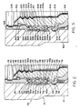
- Sealing enhancement means 56 are shown in the drawings.
- such seal enhancement means includes upper rims 58 and 60 and lower rims 62 and 64 positioned to provide the upper and lower sealing surfaces 34, 36, 42 and 44 for the upper and lower seal lips 30, 30a, 32, 32a and 38, 38a, 40 and 40a.
- Rims 58, 62 and 60, 64 are spaced from the interior and exterior surfaces of hanger 18 and housing 12 to which they are attached and provide recesses 66, 70, 68 and 72 respectively and sealing surfaces 34, 42 and 36, 44 respectively.
- the enhancement of the sealing is provided by the pressure which enters the recesses behind the rims and urges the rims in the direction of the respective sealing lips.
- Rims 58, 62 and 60, 64 should be integral with hanger 18 and housing 12 respectively. In some applications it may be possible to form the rims by machining the recesses into the hanger and housing. In other applications, it may be more desirably to weld the rims to the hanger and housing as shown at 63 and 63a. In this case it is anticipated that the upper outer rim 60 and the lower outer rim 64 both be two semicircular halves welded together.
- seal assembly 20′ After hanger 18 has been landed upon support shoulder 19, a suitable tool (not shown) is used to cause seal assembly 20′ to move downward into annular space 24. This movement moves all eight sealing lips to the positions shown in FIGURES 1 and 2 from a position above. This downward movement also moves lower wedge ring 46 into position within the upper portion of latching ring 74 to wedge ring 74 outward into latching engagement within groove 76 on the inner surface of housing 12. Since as shown in FIGURE 1, latching ring 74 after being moved into engagement in groove 76 also remains in engagement within groove 78 on the exterior of hanger 18, it locks hanger 18 within housing 12. Further, the downward movement of seal assembly 20′ brings shoulder 48 to the level of the lower portion of groove 52 which allows split ring 50 to move outwardly into position, thereby locking seal assembly 20′ to the exterior of hanger 18.
- seal assembly 120 uses only inner, upper and lower sealing surfaces 134 and 142 which are provided by rims 158 and 162.
- Rim 158 is spaced from the exterior surface of hanger 118 to provide an annular recess 166 which is open to the annular space 124 between housing 112 and hanger 118 above upper seal lips 130, 132 and 130a, 132a.
- Rim 162 is spaced from the exterior surface of hanger 118 to provide an annular recess 170 which is open to the annulus between housing 112 and hanger 114 below lower seal lips 138, 140 and 138a,140a.
- the modified form of the invention shown in FIGURE 4 has sealing enhancement means on only the lower part of the housing and hanger. Part markings are similar to previous figures but with the prefix "2" added.
- Seal assembly 220 uses only the rims 262 and 264 providing the pressure enhancement for the sealing against their surfaces 242 and 244 while upper sealing surfaces 234 and 236 are provided on the exterior of hanger 218 and the interior of housing 212.
- Rim 262 is spaced from the exterior of hanger 218 and rim 264 is spaced from the interior of housing 212 to provide the annular recesses 270 and 272 which are exposed to pressure within the annular space below seal assembly 220.
- FIGURE 5 Another modified form of the invention with sealing enhancement means on the housing only is shown in FIGURE 5 and uses similar part numbering but with the prefix "3" added.
- Seal assembly 320 uses only the outer upper and lower rims 360 and 364. This provides the recesses 368 and 372 which provides pressure enhancement for the sealing against the sealing surfaces 336 and 344.
- the pressure in the annular space is effective to provide the pressure enhancement from both above and below depending on the source of the pressure.
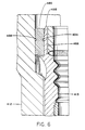
- FIGURE 6 Still another modified form of the present invention is shown in FIGURE 6 using similar numbering with the prefix "4" added.
- Seal assembly 420 utilizes the rim 458 on hanger 418 with the recess 466 exposed to pressure in the annular space above the sealing element 480 which is an annular element of soft metal positioned between the interior sealing surface 436 of the housing 412 and sealing surface 434 on the exterior of rim 458.
- the sealing element 480 is sufficiently large so that there is initial sealing of the element 480 against the sealing surfaces 434 and 436.
- this form of the invention only a single rim 458 and its attendant recess 466 are shown. It should be noted, however, that any of the four variations of this single rim and recess could be used and still achieve the improved pressure enhancement of the present invention.
- the recesses behind the rims could be filled with a suitable pressure transmitting material, such as silicone or RTV rubber, which will not interfere with the pressure enhancement but will protect the recesses from loading with well materials which might subsequently prevent proper operation of the pressure enhancement.
- a suitable pressure transmitting material such as silicone or RTV rubber
- FIGURES 1 and 2 While five forms of the present invention have been illustrated and described, it should be understood that the pressure enhancement achieved by the improvement of the present invention may be utilized singly or in any combination of the rims illustrated in FIGURES 1 and 2.
- the enhanced sealing is achieved only when the recess behind the rim is open to the pressure in the annulus.
- the rims are illustrated as being either integral with the hanger and the wellhead housing or being welded to such structures in a manner providing the necessary strength and the desired recess associated with the rim.
- the strength of the rims should be such that they respond to pressure within their recesses but not so weak that they are stressed beyond their yield point. Very slight movement of the rims is sufficient to provide a substantial improvement in the effective sealing of the sealing lips.
Landscapes
- Engineering & Computer Science (AREA)
- General Engineering & Computer Science (AREA)
- Life Sciences & Earth Sciences (AREA)
- Physics & Mathematics (AREA)
- Fluid Mechanics (AREA)
- Geology (AREA)
- Mining & Mineral Resources (AREA)
- Mechanical Engineering (AREA)
- Geochemistry & Mineralogy (AREA)
- Environmental & Geological Engineering (AREA)
- Architecture (AREA)
- General Life Sciences & Earth Sciences (AREA)
- Gasket Seals (AREA)
- Springs (AREA)
- Materials For Medical Uses (AREA)
- Polymers With Sulfur, Phosphorus Or Metals In The Main Chain (AREA)
- Paper (AREA)
- Glass Compositions (AREA)
- Seal Device For Vehicle (AREA)
- Supporting Of Heads In Record-Carrier Devices (AREA)
- Excavating Of Shafts Or Tunnels (AREA)
Priority Applications (1)
| Application Number | Priority Date | Filing Date | Title |
|---|---|---|---|
| AT88300170T ATE80440T1 (de) | 1987-04-30 | 1988-01-11 | Bohrlochkopfabdichtungen. |
Applications Claiming Priority (2)
| Application Number | Priority Date | Filing Date | Title |
|---|---|---|---|
| US44416 | 1987-04-30 | ||
| US07/044,416 US4771828A (en) | 1987-04-30 | 1987-04-30 | Wellhead seals |
Publications (3)
| Publication Number | Publication Date |
|---|---|
| EP0289106A2 true EP0289106A2 (fr) | 1988-11-02 |
| EP0289106A3 EP0289106A3 (en) | 1989-05-31 |
| EP0289106B1 EP0289106B1 (fr) | 1992-09-09 |
Family
ID=21932275
Family Applications (1)
| Application Number | Title | Priority Date | Filing Date |
|---|---|---|---|
| EP88300170A Expired - Lifetime EP0289106B1 (fr) | 1987-04-30 | 1988-01-11 | Joints pour tête de puits |
Country Status (10)
| Country | Link |
|---|---|
| US (1) | US4771828A (fr) |
| EP (1) | EP0289106B1 (fr) |
| JP (1) | JPS63272888A (fr) |
| AT (1) | ATE80440T1 (fr) |
| AU (1) | AU609079B2 (fr) |
| BR (1) | BR8801845A (fr) |
| CA (1) | CA1281282C (fr) |
| DE (1) | DE3874401T2 (fr) |
| NO (1) | NO881874L (fr) |
| SG (1) | SG36493G (fr) |
Cited By (3)
| Publication number | Priority date | Publication date | Assignee | Title |
|---|---|---|---|---|
| EP0405734A3 (en) * | 1989-06-28 | 1991-04-10 | Cooper Industries Inc. | Subsea hanger and running tool |
| AU609079B2 (en) * | 1987-04-30 | 1991-04-26 | Cooper Cameron Corporation | Wellhead seals |
| EP0405731A3 (en) * | 1989-06-30 | 1991-07-17 | Cooper Industries Inc. | Annular seal |
Families Citing this family (14)
| Publication number | Priority date | Publication date | Assignee | Title |
|---|---|---|---|---|
| GB8817554D0 (en) * | 1988-07-22 | 1988-08-24 | Cooper Ind Inc | Positioning components & energising sealing assemblies thereof |
| US5026074A (en) * | 1989-06-30 | 1991-06-25 | Cooper Industries, Inc. | Annular metal-to-metal seal |
| US5110144A (en) * | 1990-08-24 | 1992-05-05 | Cooper Industries, Inc. | Casing hanger seal assembly |
| US5129660A (en) * | 1991-02-25 | 1992-07-14 | Cooper Industries, Inc. | Seal assembly for a well housing hanger structure |
| US5193616A (en) * | 1991-08-06 | 1993-03-16 | Cooper Industries, Inc. | Tubing hanger seal assembly |
| US5285853A (en) * | 1991-12-10 | 1994-02-15 | Abb Vetco Gray Inc. | Casing hanger seal with test port |
| US6032958A (en) * | 1998-03-31 | 2000-03-07 | Hydril Company | Bi-directional pressure-energized metal seal |
| US6367844B1 (en) * | 1999-06-22 | 2002-04-09 | The United States Of America As Represented By The Administrator Of The National Aeronautics And Space Administration | Attachment fitting for pressure vessel |
| GB0318181D0 (en) * | 2003-08-02 | 2003-09-03 | Weatherford Lamb | Seal arrangement |
| US7861789B2 (en) * | 2005-02-09 | 2011-01-04 | Vetco Gray Inc. | Metal-to-metal seal for bridging hanger or tieback connection |
| US8307889B2 (en) | 2010-05-13 | 2012-11-13 | Randy Lewkoski | Assembly for controlling annuli between tubulars |
| US10113383B2 (en) * | 2012-05-10 | 2018-10-30 | Vetco Gray, LLC | Positive retention lock ring for tubing hanger |
| WO2017116871A1 (fr) * | 2015-12-30 | 2017-07-06 | Cameron International Corporation | Composants de tête de puits et procédés d'installation |
| CN114427233B (zh) * | 2022-03-01 | 2024-07-26 | 中国建筑第八工程局有限公司 | 降水井口封堵装置及其施工方法 |
Family Cites Families (13)
| Publication number | Priority date | Publication date | Assignee | Title |
|---|---|---|---|---|
| US1336738A (en) * | 1920-04-13 | Well-packer | ||
| US2047569A (en) * | 1930-02-24 | 1936-07-14 | Walter A Loomis | Safety tubing gate |
| US1983938A (en) * | 1933-01-23 | 1934-12-11 | Granville A Humason | Casing head equipment |
| US1944840A (en) * | 1933-02-24 | 1934-01-23 | Margia Manning | Control head for wells |
| US2075899A (en) * | 1933-09-12 | 1937-04-06 | Granville A Humason | Drilling head |
| US2405152A (en) * | 1943-02-20 | 1946-08-06 | Sulzer Ag | Packing for cylindrical parts |
| US2746486A (en) * | 1952-01-23 | 1956-05-22 | Gratzmuller Jean Louis | Fluid-tight assembly |
| US3279806A (en) * | 1964-02-21 | 1966-10-18 | Goodrich Co B F | Seal assembly |
| US4131287A (en) * | 1977-07-11 | 1978-12-26 | Exxon Production Research Company | Annular seal |
| US4302018A (en) * | 1980-02-29 | 1981-11-24 | Foster-Miller Associates, Inc. | Packer arrangements for oil wells and the like |
| US4595053A (en) * | 1984-06-20 | 1986-06-17 | Hughes Tool Company | Metal-to-metal seal casing hanger |
| US4641841A (en) * | 1985-08-26 | 1987-02-10 | Hughes Tool Company | Metal seal for a tubular connection |
| US4771828A (en) * | 1987-04-30 | 1988-09-20 | Cameron Iron Works, Usa, Inc. | Wellhead seals |
-
1987
- 1987-04-30 US US07/044,416 patent/US4771828A/en not_active Expired - Fee Related
-
1988
- 1988-01-11 AT AT88300170T patent/ATE80440T1/de not_active IP Right Cessation
- 1988-01-11 DE DE8888300170T patent/DE3874401T2/de not_active Expired - Fee Related
- 1988-01-11 EP EP88300170A patent/EP0289106B1/fr not_active Expired - Lifetime
- 1988-01-12 CA CA000556285A patent/CA1281282C/fr not_active Expired - Lifetime
- 1988-01-18 AU AU10347/88A patent/AU609079B2/en not_active Ceased
- 1988-01-27 JP JP63016768A patent/JPS63272888A/ja active Pending
- 1988-04-19 BR BR8801845A patent/BR8801845A/pt not_active IP Right Cessation
- 1988-04-29 NO NO881874A patent/NO881874L/no unknown
-
1993
- 1993-03-31 SG SG364/93A patent/SG36493G/en unknown
Cited By (3)
| Publication number | Priority date | Publication date | Assignee | Title |
|---|---|---|---|---|
| AU609079B2 (en) * | 1987-04-30 | 1991-04-26 | Cooper Cameron Corporation | Wellhead seals |
| EP0405734A3 (en) * | 1989-06-28 | 1991-04-10 | Cooper Industries Inc. | Subsea hanger and running tool |
| EP0405731A3 (en) * | 1989-06-30 | 1991-07-17 | Cooper Industries Inc. | Annular seal |
Also Published As
| Publication number | Publication date |
|---|---|
| EP0289106A3 (en) | 1989-05-31 |
| NO881874D0 (no) | 1988-04-29 |
| SG36493G (en) | 1993-06-11 |
| DE3874401T2 (de) | 1993-01-21 |
| US4771828A (en) | 1988-09-20 |
| AU609079B2 (en) | 1991-04-26 |
| DE3874401D1 (de) | 1992-10-15 |
| JPS63272888A (ja) | 1988-11-10 |
| ATE80440T1 (de) | 1992-09-15 |
| CA1281282C (fr) | 1991-03-12 |
| EP0289106B1 (fr) | 1992-09-09 |
| AU1034788A (en) | 1988-11-03 |
| NO881874L (no) | 1988-10-31 |
| BR8801845A (pt) | 1988-11-22 |
Similar Documents
| Publication | Publication Date | Title |
|---|---|---|
| EP0289106A2 (fr) | Joints pour tête de puits | |
| US4751965A (en) | Wellhead seal assembly | |
| US4932472A (en) | Packoff with flexible section for casing hanger | |
| US5060724A (en) | Casing hanger seal locking mechanism with detent | |
| US5026074A (en) | Annular metal-to-metal seal | |
| US4742874A (en) | Subsea wellhead seal assembly | |
| US4749047A (en) | Annular wellhead seal | |
| EP0290113B1 (fr) | Joint annulaire pour tête de puits | |
| EP0329895B1 (fr) | Dispositif de suspension et d'étanchéité | |
| EP0289105B1 (fr) | Joint pour tête de puits | |
| US5129660A (en) | Seal assembly for a well housing hanger structure | |
| US5110144A (en) | Casing hanger seal assembly | |
| EP0290112B1 (fr) | Ensemble d'étanchéité pour tête de puits immergée | |
| EP0359355B1 (fr) | Garniture d'étanchéité à coins pour une tête à puits | |
| US5094297A (en) | Casing weight set seal ring | |
| US4645214A (en) | Wellhead sealing assembly | |
| US4784222A (en) | Wellhead sealing assembly | |
| US4501441A (en) | Tension hanger landing bowl | |
| EP0340365B1 (fr) | Enceinte de puits et épaulement de mise en place | |
| US6176328B1 (en) | Drill pipe protection rings and method of using the same | |
| EP0405731B1 (fr) | Joint annulaire |
Legal Events
| Date | Code | Title | Description |
|---|---|---|---|
| PUAI | Public reference made under article 153(3) epc to a published international application that has entered the european phase |
Free format text: ORIGINAL CODE: 0009012 |
|
| AK | Designated contracting states |
Kind code of ref document: A2 Designated state(s): AT DE FR GB NL |
|
| PUAL | Search report despatched |
Free format text: ORIGINAL CODE: 0009013 |
|
| AK | Designated contracting states |
Kind code of ref document: A3 Designated state(s): AT DE FR GB NL |
|
| RAP1 | Party data changed (applicant data changed or rights of an application transferred) |
Owner name: CAMERON IRON WORKS USA, INC. (A DELAWARE CORP.) |
|
| 17P | Request for examination filed |
Effective date: 19891106 |
|
| RAP1 | Party data changed (applicant data changed or rights of an application transferred) |
Owner name: COOPER INDUSTRIES INC. |
|
| 17Q | First examination report despatched |
Effective date: 19910614 |
|
| GRAA | (expected) grant |
Free format text: ORIGINAL CODE: 0009210 |
|
| AK | Designated contracting states |
Kind code of ref document: B1 Designated state(s): AT DE FR GB NL |
|
| REF | Corresponds to: |
Ref document number: 80440 Country of ref document: AT Date of ref document: 19920915 Kind code of ref document: T |
|
| REF | Corresponds to: |
Ref document number: 3874401 Country of ref document: DE Date of ref document: 19921015 |
|
| ET | Fr: translation filed | ||
| PLBE | No opposition filed within time limit |
Free format text: ORIGINAL CODE: 0009261 |
|
| STAA | Information on the status of an ep patent application or granted ep patent |
Free format text: STATUS: NO OPPOSITION FILED WITHIN TIME LIMIT |
|
| 26N | No opposition filed | ||
| PGFP | Annual fee paid to national office [announced via postgrant information from national office to epo] |
Ref country code: DE Payment date: 19940127 Year of fee payment: 7 |
|
| PGFP | Annual fee paid to national office [announced via postgrant information from national office to epo] |
Ref country code: NL Payment date: 19940131 Year of fee payment: 7 |
|
| PGFP | Annual fee paid to national office [announced via postgrant information from national office to epo] |
Ref country code: AT Payment date: 19941214 Year of fee payment: 8 |
|
| PGFP | Annual fee paid to national office [announced via postgrant information from national office to epo] |
Ref country code: GB Payment date: 19941219 Year of fee payment: 8 |
|
| PGFP | Annual fee paid to national office [announced via postgrant information from national office to epo] |
Ref country code: FR Payment date: 19950113 Year of fee payment: 8 |
|
| PG25 | Lapsed in a contracting state [announced via postgrant information from national office to epo] |
Ref country code: NL Effective date: 19950801 |
|
| NLV4 | Nl: lapsed or anulled due to non-payment of the annual fee |
Effective date: 19950801 |
|
| PG25 | Lapsed in a contracting state [announced via postgrant information from national office to epo] |
Ref country code: DE Effective date: 19951003 |
|
| PG25 | Lapsed in a contracting state [announced via postgrant information from national office to epo] |
Ref country code: GB Effective date: 19960111 Ref country code: AT Effective date: 19960111 |
|
| REG | Reference to a national code |
Ref country code: GB Ref legal event code: 732E |
|
| GBPC | Gb: european patent ceased through non-payment of renewal fee |
Effective date: 19960111 |
|
| PG25 | Lapsed in a contracting state [announced via postgrant information from national office to epo] |
Ref country code: FR Effective date: 19960930 |
|
| REG | Reference to a national code |
Ref country code: FR Ref legal event code: ST |