EP0289214A1 - Ensemble compact de contrôle de débit de fluide et dispositif de distribution de liquide le comprenant - Google Patents
Ensemble compact de contrôle de débit de fluide et dispositif de distribution de liquide le comprenant Download PDFInfo
- Publication number
- EP0289214A1 EP0289214A1 EP88303596A EP88303596A EP0289214A1 EP 0289214 A1 EP0289214 A1 EP 0289214A1 EP 88303596 A EP88303596 A EP 88303596A EP 88303596 A EP88303596 A EP 88303596A EP 0289214 A1 EP0289214 A1 EP 0289214A1
- Authority
- EP
- European Patent Office
- Prior art keywords
- assembly
- condition
- pressure
- inlet
- liquid
- Prior art date
- Legal status (The legal status is an assumption and is not a legal conclusion. Google has not performed a legal analysis and makes no representation as to the accuracy of the status listed.)
- Granted
Links
- 239000007788 liquid Substances 0.000 title claims abstract description 50
- 239000012530 fluid Substances 0.000 title claims abstract description 43
- 238000006073 displacement reaction Methods 0.000 claims abstract description 14
- 230000004044 response Effects 0.000 claims abstract description 6
- 230000037452 priming Effects 0.000 claims description 16
- 235000013361 beverage Nutrition 0.000 claims description 6
- 238000006243 chemical reaction Methods 0.000 claims description 6
- 230000007246 mechanism Effects 0.000 claims description 5
- 239000006260 foam Substances 0.000 abstract description 29
- 235000013405 beer Nutrition 0.000 abstract description 23
- 235000001674 Agaricus brunnescens Nutrition 0.000 description 10
- 239000007789 gas Substances 0.000 description 7
- 230000000694 effects Effects 0.000 description 5
- 238000010926 purge Methods 0.000 description 5
- 238000011144 upstream manufacturing Methods 0.000 description 4
- 239000003570 air Substances 0.000 description 3
- 238000001514 detection method Methods 0.000 description 3
- 230000000717 retained effect Effects 0.000 description 3
- 238000007789 sealing Methods 0.000 description 3
- CURLTUGMZLYLDI-UHFFFAOYSA-N Carbon dioxide Chemical compound O=C=O CURLTUGMZLYLDI-UHFFFAOYSA-N 0.000 description 2
- 230000007423 decrease Effects 0.000 description 2
- 230000000994 depressogenic effect Effects 0.000 description 2
- 238000005086 pumping Methods 0.000 description 2
- IJGRMHOSHXDMSA-UHFFFAOYSA-N Atomic nitrogen Chemical compound N#N IJGRMHOSHXDMSA-UHFFFAOYSA-N 0.000 description 1
- 101100441413 Caenorhabditis elegans cup-15 gene Proteins 0.000 description 1
- 229910002092 carbon dioxide Inorganic materials 0.000 description 1
- 239000001569 carbon dioxide Substances 0.000 description 1
- 230000008859 change Effects 0.000 description 1
- 235000019987 cider Nutrition 0.000 description 1
- 230000009849 deactivation Effects 0.000 description 1
- 238000007599 discharging Methods 0.000 description 1
- 239000004615 ingredient Substances 0.000 description 1
- 235000015095 lager Nutrition 0.000 description 1
- 239000000203 mixture Substances 0.000 description 1
- 230000004048 modification Effects 0.000 description 1
- 238000012986 modification Methods 0.000 description 1
- JCXJVPUVTGWSNB-UHFFFAOYSA-N nitrogen dioxide Inorganic materials O=[N]=O JCXJVPUVTGWSNB-UHFFFAOYSA-N 0.000 description 1
- 238000002360 preparation method Methods 0.000 description 1
- 239000011435 rock Substances 0.000 description 1
- 235000014214 soft drink Nutrition 0.000 description 1
- 235000015106 stout Nutrition 0.000 description 1
Images
Classifications
-
- B—PERFORMING OPERATIONS; TRANSPORTING
- B67—OPENING, CLOSING OR CLEANING BOTTLES, JARS OR SIMILAR CONTAINERS; LIQUID HANDLING
- B67D—DISPENSING, DELIVERING OR TRANSFERRING LIQUIDS, NOT OTHERWISE PROVIDED FOR
- B67D1/00—Apparatus or devices for dispensing beverages on draught
- B67D1/08—Details
- B67D1/12—Flow or pressure control devices or systems, e.g. valves, gas pressure control, level control in storage containers
- B67D1/1202—Flow control, e.g. for controlling total amount or mixture ratio of liquids to be dispensed
- B67D1/1234—Flow control, e.g. for controlling total amount or mixture ratio of liquids to be dispensed to determine the total amount
- B67D1/1243—Flow control, e.g. for controlling total amount or mixture ratio of liquids to be dispensed to determine the total amount comprising flow or pressure sensors, e.g. for controlling pumps
Definitions
- the present invention relates to a unified assembly for control of fluid flow in a liquid dispensing system and to a liquid dispensing system which includes such an assembly.
- an exhaustible source such as a cask, keg, barrel or other container in the case of beverages
- the liquid is often pumped through lengthy piping to a dispensing tap
- air or other gas as may be used in the dispensing
- the present invention was primarily developed for use in dispensing systems for beverages such as beer, stout, lager, cider and so-called soft drinks which are themselves or have liquid ingredients which are supplied by fluid pressurising means such as a pump from an exhaustible container, it will be realised that the invention may readily be applied to liquid dispensing systems other than for beverages.
- a unified assembly for control of fluid flow in a liquid dispensing system and comprising an inlet port and an outlet port; electric switch means for controlling actuation of a fluid pressurising device by which liquid under pressure is intended to be supplied to the inlet port, said switch means having a first condition in which the pressurising device is intended to be operated and a second condition in which the pressurising device is intended to be inoperative; first pressure sensing means which is responsive to fluid pressure at the outlet and reacts when said fluid pressure exceeds a predetermined value to adjust the switch means from its first condition to its second condition; second pressure sensing means which is responsive to fluid pressure at the inlet and reacts when said fluid pressure is less than a second predetermined value to adjust the switch means from its first condition to its second condition, said second predetermined value being less than the first predetermined value; a bleed outlet; a bleed valve normally closing communication between the inlet and the bleed outlet, and a priming facility comprising first means for adjusting the bleed valve to
- a liquid dispensing system comprising a unified assembly as specified in the immediately preceding paragraph; a source of liquid to be dispensed; electrically controlled fluid pressurising means controlled by the switch means for supplying liquid under pressure from the source to the inlet of the assembly and a tap communicating with the outlet of the assembly and through which the liquid is to be dispensed.
- the fluid pressurising means will usually be in the form of an electrically driven pump by which the liquid is drawn from a container and supplied under pressure to the inlet and which is controlled by a simple on/off micro switch in the unified assembly; for convenience, the pressurising means will hereinafter be referred to as a pump although it will be appreciated that other such means can be utilised such as gas under pressure by which the liquid is displaced from its container where the gas pressure is electrically controlled as required for the supply of liquid to the inlet of the unified assembly.
- the pressure of liquid at the outlet of the unified assembly rapidly decreases until the fluid pressure sensed by the first sensing means becomes less than the first predetermined value and the first means reacts to adjust the switch device to its first condition to start the pump (it will be apparent that under these conditions and provided that the pump starts in its normal manner to restore and maintain pressure, the fluid pressure sensed at the inlet by the second means will still exceed the second predetermined value of fluid pressure so this second means is without effect on the switch means). It will also be realised that the first pressure sensing means effectively acts as a demand control for supply of the liquid as the dispensing tap is opened and closed.
- the rapidity of the reaction from the second pressure means to stop the pump when froth or foam is applied to the inlet is desirably such that the froth or foam is restricted in the conduiting of the system from the container, through the pump and to the part of the unified assembly where the low pressure froth or foam is detected by the second pressure sensing means while the system downstream of the unified assembly can remain charged with liquid.
- the unified assembly includes a non-return valve through which the inlet communicates with the outlet.
- This non-return valve may be biased, conveniently by adjustable spring means, to alleviate low pressure froth or foam from entering the system downstream of that non-return valve and serves to alleviate liquid in the aforementioned downstream part of the system from flowing into the froth or foam upstream of the non-return valve.
- the system can readily be purged of the froth or foam without discharging the froth or foam through the dispensing tap.
- the bleed valve is operated, preferably manually to open communication between the inlet and the bleed outlet; in addition the switch device is adjusted to its first condition to actuate the electric pump so that liquid is drawn from the source and applied under pressure to the inlet to drive the froth or foam through the bleed outlet.
- the bleed valve When liquid is observed to emerge from the bleed outlet, the bleed valve is permitted to close communication between the inlet and that outlet and the system is primed for further dispensing by operation of the dispensing tap.
- the second pressure sensing means will respond to the increased pressure of the liquid which purges the system of the froth or foam until the fluid pressure sensed by the second pressure sensing means exceeds the second predetermined value and the second pressure sensing means is without effect on the switch device which thereby reverts to a condition to operate the pump.
- the priming facility can be arranged to adjust the bleed valve to open communication from the inlet to the bleed outlet prior to, simultaneously with, or subsequent to the adjustment of the electrical switch device to its first condition; preferably however the pump starts while the inlet communicates with the bleed outlet or as that communication is being effected. It is also preferred, bearing in mind the aim to achieve a compact and unified assembly, that the second means of the priming facility for adjusting the electrical switch device is manually operable and is effected during operation of the first means of the priming facility to cause a reaction on the second pressure sensing means and that reaction serves to adjust the switch device from its second condition to its first condition and thereby causes the pump to operate.
- the switch device is conveniently biased to its first condition and each of the first and second pressure sensing means reacts on the switch to displace it against its biasing and thereby effect the adjustment from its normal first condition (corresponding to the pump being driven) to its second condition (corresponding to the pump being off).
- the first and second pressure sensing means preferably comprise biased sensing members which are displaceable in response to variations in fluid pressure at the inlet or outlet as the case may be and the displacement of these members causes an adjustment of the switch device as appropriate.
- the displaceable members of the first and second pressure sensing means control actuation of the switch means through a lever mechanism, preferably a rocking lever which is common to both the first and second pressure sensing means.
- the biased sensing member of the first pressure sensing means which is displaceable in response to variations in fluid pressure at the outlet will be displaceable under high liquid pressure and against its biasing to adjust the switch device from its first to its second condition while the biased sensing member of the second pressure sensing means which is displaceable in response to variations in fluid pressure at the inlet will be displaceable against low fluid pressure and under its biasing to adjust the switch means from its first to its second condition.
- the biasing of the sensing members for the first and second pressure sensing means is adjustable for setting-up the unified assembly to react with required first and second predetermined pressure values.
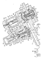
- liquid dispensing system which includes a unified assembly for control of fluid flow in accordance with the present invention will now be described, by way of example only, with reference to the accompanying illustrative drawing which shows the unified assembly in section while the remaining features of the system are shown in schematic form.
- the system illustrated schematically is typically that of a simple beverage dispensing system in which, say, beer from a cask 1 is drawn on demand by an electrically driven pump 2 to be supplied by way of a pipe 3 and a unified assembly 4 in the pipe 3 to a conventional open/closed dispensing tap 5.
- the unified assembly 4 provides a control for beer flow through the system and has an inlet passage 6 connected to the outlet from the pump 2.
- the passage 6 communicates by way of a port 7 and a non-return valve 8 with a pressure chamber 9.
- the chamber 9 is in constant communication (as indicated by the broken line 10) with an outlet 11 of the unified assembly and this outlet communicates through the pipe 3 with the dispensing tap 5.
- the non-return valve 8 comprises a pad 11 on a carrier 12 which is spring loaded at 13 to normally close the port 7.
- the pad 11 is lifted from the port 7 to open communication between that port and the chamber 9 from which beer can flow to the tap 5.
- the chamber 9 is associated with a high pressure sensing device and is partly defined by a piston 14 which is displaceable in a piston cylinder 15 formed in a housing 16 of the assembly and which is spring loaded at 17 in a sense to contract the chamber 9.
- the spring 17 reacts between a shoulder 18 of the piston and a cup 19 in the piston cylinder.
- the cup 19 is preferably restrained from rotation within the cylinder 15 but is axially adjustable along the cylinder by a screw thread mechanism 20 which connects a tubular stem 21 on the cup 15 with the housing 16. Access to the mechanism 20 for adjusting the axial position of the cup 19 within the piston cylinder is achieved through a port 22 which is normally closed by a removable cap 23.
- axial displacement of the cup 19 serves to adjust the biasing force exerted by the spring 17 on the piston.
- Projecting radially into the piston cylinder 15 and through an opening 24 in the wall of cup 19 is an end 25 of a rocking lever 26 which is pivotally mounted at 27 on the housing 16.
- the end 25 of the rocking lever is located to abut an end face 28 of the piston 14 axially remote from the pressure chamber 9 so that during axial displacement of the piston in a sense to increase the volume of chamber 9 causes the lever 26 to rock in a clockwise direction (as shown in the drawing) about the pivot 27.
- the rocking lever 26 controls operation of a microswitch 28 carried by the housing 16.
- the microswitch 28 has terminals 29 which are incorporated with terminals 30 of the electrical pump 2 and with a power source (not shown) in a circuit which serves to control the on/off operation of the pump 2.
- the switch 28 operation is determined by a displaceable plunger 31 of the switch which is spring loaded to be urged outwardly of the switch body and into a first condition of the switch in which the electrical circuit is normally closed and the pump 2 operates. Depression of the plunger 31 against its spring loading moves the switch 28 into a second condition where the electrical circuit is open and the pump 2 is inoperative. Movement of the plunger 31 is effected through an abutment 32 on the rocking lever 26 which is on the side of the pivot 27 remote from the lever end 25.
- the spring loaded carrier 12 of the non-return valve 8 is conveniently mounted coaxially within a bore of the piston 14 and the biasing spring 13 of the carrier 12 reacts against a rod 33 which is axially adjustable within the coaxial bore of the piston 14.
- the end of the rod remote from the valve 8 connects with a shaft 34 which screw threadedly engages with the bore of the tubular stem 21 on the cup 19 so that the axial position of the rod 33 can be adjusted relative to the cup 19.
- the rod 33 is in sealed sliding engagement with the piston 14 so that the piston can be displaced axially independently of the rod 33; it will be appreciated that by axial adjustment in the position of the rod 33 the biasing force exerted by the spring 13 on the non-return valve can be adjusted. This latter adjustment being effected through the port 22 and by rotation of the shaft 34 within the stem 21.
- a low pressure detection chamber 35 formed between a pair of opposing flexible diaphragms 36 and 37 having flanged outer peripheries which are sealed to the housing 16.
- the central region of the diaphragm 37 is connected to the end of a generally cylindrical plunger 38 which is displaceable in the housing 16 substantially parallel with the piston 14 and is located on the side of the microswitch plunger 31 remote from the piston 14.
- the end of the plunger 38 remote from the diaphragm 37 has an external flange 39 which is capable of abutment with an end 40 of the rocking lever 26, said end 40 being on the side of the switch plunger 31 remote from the pivot 27.
- the plunger 38 is biased axially by a spring 41 in a tubular part of that plunger and relative to the housing 16 in a sense to contract the chamber 35 (so that the diaphragm 37 is urged towards the diaphragm 36).
- the relationship between the flange 39 and end 40 of the rocking lever is such that if the plunger 38 is displaced under its spring loading to the end of travel permitted for the plunger 38 (as indicated by the broken lines in the drawing), the rocking lever 26 will be displaced about the pivot 27 in a clockwise direction (as shown by the broken lines) to depress the plunger 31, switch off the pump 2, and thereby provide a control for the pump which is independent of the piston 14 when the chamber 9 is in a contracted condition.
- the biasing force exerted by the spring 41 on the plunger 38 is adjustable by rotation of a screw threaded rod 42 relative to the housing 16 with which it screw threadedly engages at 42a and which rod is located within the tubular part of the plunger 38 so that its end reacts against the spring 41.
- the pressure within the chamber 35 is sufficient to displace the diaphragm 37 and thereby the plunger 38 against the spring biasing 41 to the position shown in the drawing and the spring biasing is adjusted accordingly.
- the rocking lever 26 With the pressure chamber 9 in a contracted condition during a dispensing operation, the rocking lever 26 has sufficient clearance beneath the flange 39 to be displaced, under the biasing force of the switch plunger 31, for the switch to be in its first condition in which the pump is operative.
- the rocking lever 26 can pivot to depress the plunger 31 and thereby switch off the pump 2 while the beer pressure in the chamber 35 is adequate to maintain that chamber in its expanded condition and thereby the plunger 38 in the position drawn.
- a mixture of beer and gas (usually one or more of air, nitrogen or carbon dioxide gases) will eventually be drawn into the pump and supplied as froth or foam to the inlet passage 6 and low pressure detection chamber 35. It is a usual condition of liquid pumps that their pressure performance when pumping gas, froth or foam is less than when pumping liquid. This froth or foam will then provide a relatively lower pressure in the chamber 35 than that provided by the normal through-flow of beer and this low pressure is inadequate to maintain the diaphragm 37 and plunger 38 against the force of the biasing spring 41.
- the spring loading on the non-return valve 8 is adjusted so that the low pressure of the froth or foam is inadequate to lift the non-return valve from its seating thereby ensuring that the froth or foam is retained in the system upstream of the non-return valve.
- the unified assembly 4 includes a priming facility shown generally at 45.
- This facility comprises a bleed valve 46 which is manually operable to open and close communication between the low pressure detection chamber 35 and a bleed outlet 47 in the housing.
- the bleed valve 46 has a mushroom valve member 48, the stem 49 of which extends through a port 50 in the diaphragm 36 coaxially with the plunger 38.
- the stem 49 has a flanged end 51 remote from its mushroom head which is seated within a sealing member 52 sealed to the housing 16.
- the sealing member 52 forms a chamber 53 with a recess in the housing 16 and the bleed outlet 47 is in constant communication with the chamber 53.
- a spring 54 reacts between the housing 16 and the flanged end 51 of the mushroom valve to bias the mushroom head into sealing engagement with the diaphragm 36.
- the port 50 is thereby normally closed to communication with the chamber 35 and the latter is thus normally closed to communication with the bleed outlet 47.
- Movably mounted on the housing is a cup 55 which abuts the seal 52 and therethrough bears on the flanged end 51 of the mushroom valve stem.
- the cup 55 presents a button which is manually displaceable to lift the mushroom valve member in the drawing and against the spring loading 54 to open communication between the chamber 35 and the port 50 thereby permitting the froth in the inlet passage 6 to communicate with the bleed outlet 47.
- the priming facility 45 includes means whereby the pump 2 will operate to draw beer into the system from the cask 1 and thereby drive the froth or foam from the inlet passage, through the open port 50 and to the bleed outlet 47.
- the manual displacement of the mushroom valve 48 against its spring biasing and to open the port 50 is arranged to be sufficient for the mushroom head of the valve to abut the diaphragm 37 (when that diaphragm is in the position shown by the broken line) and displace that diaphragm together with the plunger 38 against the biasing force of the spring 41 so that the diaphragm 37 and its plunger revert to the position shown in the drawing.
- the button 55 can now be released so that the mushroom head reverts to its normal condition to close the port 50 while the pressure of beer in the inlet passage 6 and chamber 35 retain the latter chamber in an expanded condition and the plunger 38 against its spring biasing in the position shown.
- the system is now in a condition for normal dispensing through the tap 5.
- the lengths of piping between the cask and the pump 2 and between the pump and the inlet passage 6 are as short as convenient, possibly with the unified assembly 4 being mounted on the pump 2. It will also be apparent that during the purging of froth or foam from the system and the priming of the system as discussed above, the non- return valve 8 alleviates beer in the system downstream thereof from flowing into the inlet passage 6.
- the piston 14 in the above described embodiment we have referred to the piston 14 as being axially slidable over the rod 33 while the latter is screw adjustable within the tubular stem 21 for the purpose of adjusting the spring biasing 13.
- the rod 33 may be axially slidable within the tubular stem 21 and in screw threaded engagement with the bore of the piston 14 so that rotation of the rod 33 in the piston adjusts the biasing force exerted by the spring 13 on the non-return valve.
- the rod 33 will be displaced axially in unison with the piston 14 and that the biasing force exerted by the spring 13 will vary during axial displacement of the piston 14.
Landscapes
- Chemical & Material Sciences (AREA)
- Analytical Chemistry (AREA)
- Devices For Dispensing Beverages (AREA)
- Loading And Unloading Of Fuel Tanks Or Ships (AREA)
- Sampling And Sample Adjustment (AREA)
- Pipe Accessories (AREA)
- Cyclones (AREA)
Priority Applications (1)
| Application Number | Priority Date | Filing Date | Title |
|---|---|---|---|
| AT88303596T ATE60305T1 (de) | 1987-04-27 | 1988-04-21 | Kompaktanlage zur durchflussueberwachung einer fluessigkeit und fluessigkeitsspendevorrichtung mit solcher anlage. |
Applications Claiming Priority (2)
| Application Number | Priority Date | Filing Date | Title |
|---|---|---|---|
| GB8709910 | 1987-04-27 | ||
| GB8709910A GB2204019B (en) | 1987-04-27 | 1987-04-27 | A unified assembly for control of fluid flow and a liquid dispensing system which includes such assembly. |
Publications (2)
| Publication Number | Publication Date |
|---|---|
| EP0289214A1 true EP0289214A1 (fr) | 1988-11-02 |
| EP0289214B1 EP0289214B1 (fr) | 1991-01-23 |
Family
ID=10616416
Family Applications (1)
| Application Number | Title | Priority Date | Filing Date |
|---|---|---|---|
| EP88303596A Expired - Lifetime EP0289214B1 (fr) | 1987-04-27 | 1988-04-21 | Ensemble compact de contrôle de débit de fluide et dispositif de distribution de liquide le comprenant |
Country Status (13)
| Country | Link |
|---|---|
| US (1) | US4811862A (fr) |
| EP (1) | EP0289214B1 (fr) |
| JP (1) | JP2589539B2 (fr) |
| AT (1) | ATE60305T1 (fr) |
| AU (1) | AU590480B2 (fr) |
| CA (1) | CA1283636C (fr) |
| DE (1) | DE3861618D1 (fr) |
| ES (1) | ES2020329B3 (fr) |
| GB (1) | GB2204019B (fr) |
| GR (1) | GR3001422T3 (fr) |
| IE (1) | IE60322B1 (fr) |
| MY (1) | MY103269A (fr) |
| NZ (1) | NZ224350A (fr) |
Cited By (2)
| Publication number | Priority date | Publication date | Assignee | Title |
|---|---|---|---|---|
| EP0515993A1 (fr) * | 1991-05-26 | 1992-12-02 | Joseph Feldman | Valve de dosage de sirop dans une installation de préparation de boissons carboniques aromatisées |
| EP1343714A4 (fr) * | 2000-11-15 | 2006-05-31 | Shurflo Pump Mfg Co Inc | Dispositif et procede de distribution rapide de fluides comestibles au moyen d'un diffuseur |
Families Citing this family (3)
| Publication number | Priority date | Publication date | Assignee | Title |
|---|---|---|---|---|
| GB9207384D0 (en) * | 1992-04-03 | 1992-05-13 | Diversey Corp | Dispenser |
| US5244119A (en) * | 1992-07-07 | 1993-09-14 | Pittman Phillip D | Apparatus for monitoring dispensed fluid |
| US5896898A (en) * | 1993-04-05 | 1999-04-27 | Diversey Lever, Inc. | Dispenser |
Citations (4)
| Publication number | Priority date | Publication date | Assignee | Title |
|---|---|---|---|---|
| GB1545447A (en) * | 1977-11-05 | 1979-05-10 | Pektron Ltd | Arrangement for dispensing liquids |
| GB2094269A (en) * | 1981-03-06 | 1982-09-15 | Distillers Co Carbon Dioxide | Apparatus for dispensing beer or other liquid from a container |
| US4456149A (en) * | 1981-10-21 | 1984-06-26 | Venturon Corporation, Inc. | Water dispensing system |
| GB2140389A (en) * | 1983-05-26 | 1984-11-28 | Itt Jabsco Limited | Beverage dispensing apparatus |
Family Cites Families (5)
| Publication number | Priority date | Publication date | Assignee | Title |
|---|---|---|---|---|
| US3446238A (en) * | 1964-10-06 | 1969-05-27 | Britt Tech Corp | Pressure actuated valve |
| FR2106788A5 (fr) * | 1970-09-24 | 1972-05-05 | Equip Menager Fse | |
| US3711222A (en) * | 1971-01-11 | 1973-01-16 | E Hartley | Pumping system |
| US3878970A (en) * | 1974-02-11 | 1975-04-22 | Perlick Company Inc | Beer dispensing instrumentalities and method |
| US4081621A (en) * | 1976-04-26 | 1978-03-28 | Carr-Griff, Inc. | Pressure switch with diaphragm and valve means |
-
1987
- 1987-04-27 GB GB8709910A patent/GB2204019B/en not_active Expired - Lifetime
-
1988
- 1988-04-21 ES ES88303596T patent/ES2020329B3/es not_active Expired - Lifetime
- 1988-04-21 DE DE8888303596T patent/DE3861618D1/de not_active Expired - Fee Related
- 1988-04-21 AT AT88303596T patent/ATE60305T1/de not_active IP Right Cessation
- 1988-04-21 EP EP88303596A patent/EP0289214B1/fr not_active Expired - Lifetime
- 1988-04-22 NZ NZ224350A patent/NZ224350A/xx unknown
- 1988-04-25 JP JP63102326A patent/JP2589539B2/ja not_active Expired - Lifetime
- 1988-04-26 MY MYPI88000435A patent/MY103269A/en unknown
- 1988-04-26 CA CA000565051A patent/CA1283636C/fr not_active Expired - Lifetime
- 1988-04-27 AU AU15213/88A patent/AU590480B2/en not_active Ceased
- 1988-04-27 US US07/186,614 patent/US4811862A/en not_active Expired - Lifetime
- 1988-04-28 IE IE124988A patent/IE60322B1/en not_active IP Right Cessation
-
1991
- 1991-01-31 GR GR91400123T patent/GR3001422T3/el unknown
Patent Citations (4)
| Publication number | Priority date | Publication date | Assignee | Title |
|---|---|---|---|---|
| GB1545447A (en) * | 1977-11-05 | 1979-05-10 | Pektron Ltd | Arrangement for dispensing liquids |
| GB2094269A (en) * | 1981-03-06 | 1982-09-15 | Distillers Co Carbon Dioxide | Apparatus for dispensing beer or other liquid from a container |
| US4456149A (en) * | 1981-10-21 | 1984-06-26 | Venturon Corporation, Inc. | Water dispensing system |
| GB2140389A (en) * | 1983-05-26 | 1984-11-28 | Itt Jabsco Limited | Beverage dispensing apparatus |
Cited By (2)
| Publication number | Priority date | Publication date | Assignee | Title |
|---|---|---|---|---|
| EP0515993A1 (fr) * | 1991-05-26 | 1992-12-02 | Joseph Feldman | Valve de dosage de sirop dans une installation de préparation de boissons carboniques aromatisées |
| EP1343714A4 (fr) * | 2000-11-15 | 2006-05-31 | Shurflo Pump Mfg Co Inc | Dispositif et procede de distribution rapide de fluides comestibles au moyen d'un diffuseur |
Also Published As
| Publication number | Publication date |
|---|---|
| AU590480B2 (en) | 1989-11-02 |
| NZ224350A (en) | 1989-09-27 |
| MY103269A (en) | 1993-05-29 |
| JPS6423992A (en) | 1989-01-26 |
| GB2204019A (en) | 1988-11-02 |
| AU1521388A (en) | 1988-10-27 |
| ES2020329B3 (es) | 1991-08-01 |
| DE3861618D1 (de) | 1991-02-28 |
| US4811862A (en) | 1989-03-14 |
| IE881249L (en) | 1988-10-27 |
| GB8709910D0 (en) | 1987-06-03 |
| CA1283636C (fr) | 1991-04-30 |
| GB2204019B (en) | 1990-09-26 |
| ATE60305T1 (de) | 1991-02-15 |
| JP2589539B2 (ja) | 1997-03-12 |
| GR3001422T3 (en) | 1992-09-25 |
| EP0289214B1 (fr) | 1991-01-23 |
| IE60322B1 (en) | 1994-06-29 |
Similar Documents
| Publication | Publication Date | Title |
|---|---|---|
| EP1096873B1 (fr) | Distributeur de liquide sous pression utilisant une source de gaz sous pression separee | |
| US5178799A (en) | Carbonated beverage dispensing apparatus | |
| US6196418B1 (en) | Carbonated and non-carbonated water source and water pressure booster | |
| EP0105526B1 (fr) | Dispositif de commande d'une pompe à actionnement pneumatique | |
| US5855296A (en) | Combined carbonator and water pressure booster apparatus | |
| US4818444A (en) | Fluid pressure control valve and a system which includes such a valve | |
| US4350503A (en) | Fluid flow metering device | |
| EP1113977A1 (fr) | Dispositif de surete pour aerateur de liquides | |
| US6216913B1 (en) | Self-contained pneumatic beverage dispensing system | |
| EP0289214B1 (fr) | Ensemble compact de contrôle de débit de fluide et dispositif de distribution de liquide le comprenant | |
| AU2025202738A1 (en) | Systems and methods for dispensing a beverage | |
| RU2433947C2 (ru) | Раздаточное устройство для жидкости | |
| US3788343A (en) | Liquid dispensing apparatus | |
| GB2066932A (en) | Pressure regulator and safety valve assembly | |
| EP0300701A1 (fr) | Distributeur de liquides | |
| GB2438395A (en) | Liquid dispenser | |
| US7766309B1 (en) | Carbon dioxide manifold | |
| GB2190007A (en) | Liquid aerating apparatus with safety valve | |
| US3032055A (en) | Liquid dispenser | |
| WO2003087969A1 (fr) | Regulateur de pression | |
| JPH0612494B2 (ja) | 感温式ガス圧力調整弁 | |
| JP2003104495A (ja) | 減圧弁 |
Legal Events
| Date | Code | Title | Description |
|---|---|---|---|
| PUAI | Public reference made under article 153(3) epc to a published international application that has entered the european phase |
Free format text: ORIGINAL CODE: 0009012 |
|
| AK | Designated contracting states |
Kind code of ref document: A1 Designated state(s): AT BE CH DE ES FR GB GR IT LI LU NL SE |
|
| 17P | Request for examination filed |
Effective date: 19881006 |
|
| RAP1 | Party data changed (applicant data changed or rights of an application transferred) |
Owner name: GUINNESS BREWING WORLDWIDE LIMITED |
|
| 17Q | First examination report despatched |
Effective date: 19900612 |
|
| GRAA | (expected) grant |
Free format text: ORIGINAL CODE: 0009210 |
|
| AK | Designated contracting states |
Kind code of ref document: B1 Designated state(s): AT BE CH DE ES FR GR IT LI LU NL SE |
|
| REF | Corresponds to: |
Ref document number: 60305 Country of ref document: AT Date of ref document: 19910215 Kind code of ref document: T |
|
| REF | Corresponds to: |
Ref document number: 3861618 Country of ref document: DE Date of ref document: 19910228 |
|
| ET | Fr: translation filed | ||
| ITF | It: translation for a ep patent filed | ||
| PLBE | No opposition filed within time limit |
Free format text: ORIGINAL CODE: 0009261 |
|
| STAA | Information on the status of an ep patent application or granted ep patent |
Free format text: STATUS: NO OPPOSITION FILED WITHIN TIME LIMIT |
|
| 26N | No opposition filed | ||
| REG | Reference to a national code |
Ref country code: GR Ref legal event code: FG4A Free format text: 3001422 |
|
| EPTA | Lu: last paid annual fee | ||
| EAL | Se: european patent in force in sweden |
Ref document number: 88303596.6 |
|
| PGFP | Annual fee paid to national office [announced via postgrant information from national office to epo] |
Ref country code: AT Payment date: 19950412 Year of fee payment: 8 |
|
| PGFP | Annual fee paid to national office [announced via postgrant information from national office to epo] |
Ref country code: CH Payment date: 19950413 Year of fee payment: 8 |
|
| PGFP | Annual fee paid to national office [announced via postgrant information from national office to epo] |
Ref country code: SE Payment date: 19950419 Year of fee payment: 8 |
|
| PGFP | Annual fee paid to national office [announced via postgrant information from national office to epo] |
Ref country code: GR Payment date: 19950428 Year of fee payment: 8 |
|
| PGFP | Annual fee paid to national office [announced via postgrant information from national office to epo] |
Ref country code: LU Payment date: 19950601 Year of fee payment: 8 |
|
| PGFP | Annual fee paid to national office [announced via postgrant information from national office to epo] |
Ref country code: FR Payment date: 19960410 Year of fee payment: 9 |
|
| PG25 | Lapsed in a contracting state [announced via postgrant information from national office to epo] |
Ref country code: LU Free format text: LAPSE BECAUSE OF NON-PAYMENT OF DUE FEES Effective date: 19960421 Ref country code: AT Effective date: 19960421 |
|
| PG25 | Lapsed in a contracting state [announced via postgrant information from national office to epo] |
Ref country code: SE Effective date: 19960422 |
|
| PGFP | Annual fee paid to national office [announced via postgrant information from national office to epo] |
Ref country code: ES Payment date: 19960429 Year of fee payment: 9 Ref country code: DE Payment date: 19960429 Year of fee payment: 9 |
|
| PG25 | Lapsed in a contracting state [announced via postgrant information from national office to epo] |
Ref country code: LI Effective date: 19960430 Ref country code: CH Effective date: 19960430 |
|
| PGFP | Annual fee paid to national office [announced via postgrant information from national office to epo] |
Ref country code: NL Payment date: 19960430 Year of fee payment: 9 |
|
| PGFP | Annual fee paid to national office [announced via postgrant information from national office to epo] |
Ref country code: BE Payment date: 19960612 Year of fee payment: 9 |
|
| PG25 | Lapsed in a contracting state [announced via postgrant information from national office to epo] |
Ref country code: GR Free format text: THE PATENT HAS BEEN ANNULLED BY A DECISION OF A NATIONAL AUTHORITY Effective date: 19961031 |
|
| REG | Reference to a national code |
Ref country code: GR Ref legal event code: MM2A Free format text: 3001422 |
|
| REG | Reference to a national code |
Ref country code: CH Ref legal event code: PL |
|
| EUG | Se: european patent has lapsed |
Ref document number: 88303596.6 |
|
| PG25 | Lapsed in a contracting state [announced via postgrant information from national office to epo] |
Ref country code: ES Free format text: LAPSE BECAUSE OF NON-PAYMENT OF DUE FEES Effective date: 19970422 |
|
| PG25 | Lapsed in a contracting state [announced via postgrant information from national office to epo] |
Ref country code: BE Effective date: 19970430 |
|
| BERE | Be: lapsed |
Owner name: GUINNESS BREWING WORLDWIDE LTD Effective date: 19970430 |
|
| PG25 | Lapsed in a contracting state [announced via postgrant information from national office to epo] |
Ref country code: NL Effective date: 19971101 |
|
| PG25 | Lapsed in a contracting state [announced via postgrant information from national office to epo] |
Ref country code: FR Free format text: LAPSE BECAUSE OF NON-PAYMENT OF DUE FEES Effective date: 19971231 |
|
| PG25 | Lapsed in a contracting state [announced via postgrant information from national office to epo] |
Ref country code: DE Free format text: LAPSE BECAUSE OF NON-PAYMENT OF DUE FEES Effective date: 19980101 |
|
| NLV4 | Nl: lapsed or anulled due to non-payment of the annual fee |
Effective date: 19971101 |
|
| REG | Reference to a national code |
Ref country code: FR Ref legal event code: ST |
|
| REG | Reference to a national code |
Ref country code: ES Ref legal event code: FD2A Effective date: 19990301 |
|
| PG25 | Lapsed in a contracting state [announced via postgrant information from national office to epo] |
Ref country code: IT Free format text: LAPSE BECAUSE OF NON-PAYMENT OF DUE FEES;WARNING: LAPSES OF ITALIAN PATENTS WITH EFFECTIVE DATE BEFORE 2007 MAY HAVE OCCURRED AT ANY TIME BEFORE 2007. THE CORRECT EFFECTIVE DATE MAY BE DIFFERENT FROM THE ONE RECORDED. Effective date: 20050421 |