EP0289364A2 - Systèmes de suspension de véhicule - Google Patents
Systèmes de suspension de véhicule Download PDFInfo
- Publication number
- EP0289364A2 EP0289364A2 EP88303978A EP88303978A EP0289364A2 EP 0289364 A2 EP0289364 A2 EP 0289364A2 EP 88303978 A EP88303978 A EP 88303978A EP 88303978 A EP88303978 A EP 88303978A EP 0289364 A2 EP0289364 A2 EP 0289364A2
- Authority
- EP
- European Patent Office
- Prior art keywords
- strut
- struts
- pair
- chamber
- wheels
- Prior art date
- Legal status (The legal status is an assumption and is not a legal conclusion. Google has not performed a legal analysis and makes no representation as to the accuracy of the status listed.)
- Granted
Links
Images

Classifications
-
- B—PERFORMING OPERATIONS; TRANSPORTING
- B60—VEHICLES IN GENERAL
- B60G—VEHICLE SUSPENSION ARRANGEMENTS
- B60G17/00—Resilient suspensions having means for adjusting the spring or vibration-damper characteristics, for regulating the distance between a supporting surface and a sprung part of vehicle or for locking suspension during use to meet varying vehicular or surface conditions, e.g. due to speed or load
- B60G17/015—Resilient suspensions having means for adjusting the spring or vibration-damper characteristics, for regulating the distance between a supporting surface and a sprung part of vehicle or for locking suspension during use to meet varying vehicular or surface conditions, e.g. due to speed or load the regulating means comprising electric or electronic elements
- B60G17/018—Resilient suspensions having means for adjusting the spring or vibration-damper characteristics, for regulating the distance between a supporting surface and a sprung part of vehicle or for locking suspension during use to meet varying vehicular or surface conditions, e.g. due to speed or load the regulating means comprising electric or electronic elements characterised by the use of a specific signal treatment or control method
-
- B—PERFORMING OPERATIONS; TRANSPORTING
- B60—VEHICLES IN GENERAL
- B60G—VEHICLE SUSPENSION ARRANGEMENTS
- B60G21/00—Interconnection systems for two or more resiliently-suspended wheels, e.g. for stabilising a vehicle body with respect to acceleration, deceleration or centrifugal forces
- B60G21/02—Interconnection systems for two or more resiliently-suspended wheels, e.g. for stabilising a vehicle body with respect to acceleration, deceleration or centrifugal forces permanently interconnected
- B60G21/06—Interconnection systems for two or more resiliently-suspended wheels, e.g. for stabilising a vehicle body with respect to acceleration, deceleration or centrifugal forces permanently interconnected fluid
-
- B—PERFORMING OPERATIONS; TRANSPORTING
- B60—VEHICLES IN GENERAL
- B60G—VEHICLE SUSPENSION ARRANGEMENTS
- B60G2204/00—Indexing codes related to suspensions per se or to auxiliary parts
- B60G2204/80—Interactive suspensions; arrangement affecting more than one suspension unit
Definitions
- the present invention relates to vehicle suspensions.
- a suspension system of the type defined for a vehicle having a structure supported on at least two pairs of wheels by means of a liquid-filled strut for each wheel of first and second pairs of wheels, first and second valves controlled by sensors responsive to up-and-down movement of respective wheels of a first wheel pair to admit liquid under pressure or release liquid to or from a chamber of the respective struts to resist vehicle roll, a third valve controlled by a sensor responsive to up-and-down movement of the structure relative to the second pair of wheels to admit or release liquid under pressure to or from both struts of the second pair, the struts of the second pair each having a second liquid chamber the volume of which varies with the up-and-down movement, each such second chamber being in open communication with the chamber of a strut of the first pair so that the pressure in said second chamber of each strut of the second pair varies with the pressure in the first chamber of one of the struts
- a suspension system of the type defined is modified in that each strut has a sensor associated therewith for indicating the amount and sense of departure from a datum position and the system includes means for controlling the flow rate through each valve to or from the associated struts in such a manner that each said flow rate is proportional to the sensed departure (or the algebraic sum of the sensed departures) from the datum position or positions, the direction of flow being such as to restore the associated strut or struts to datum position(s).
- each valve whenever it senses movement from a predetermined position opens fully to connect the associated strut or struts either fully to the high pressure source of liquid or fully to drain.
- the suspension system shown in Figure 1 serves to support a vehicle structure 1 on a pair of rear wheels 2 and a pair of steered front wheels 3.
- Each rear wheel 2 is connected to the structure for example by means of a swing axle 4 while each front wheel 3 is connected to the structure 1 by a suspension linkage 5.
- the structure 1 is also supported on the swing axles 4 and suspension linkages 5 by means of telescopic struts 6 and 7 at the rear and front of the vehicle respectively.
- Each of the rear struts 6 has a liquid chamber 8 of volume which varies in accordance with the length of the strut and which is connected by a line 9 to a liquid chamber 10 of the front strut on the opposite side of the vehicle.
- the liquid chambers 8 are formed in the upper parts of the struts 6, above the piston-forming portion 11 of the struts, the chambers 10 of the front struts 7 are formed below the pistons 12 of the front struts. Accordingly, liquid displaced from a rear chamber 8 by upward movement of the associated wheel 2 relative to the structure 1 will increase the volume of the chamber 10 of the front strut 7 on the opposite side of the vehicle, thereby shortening the effective length of this front strut and thus opposing vehicle roll.
- Futher variable-volume liquid chambers 13 are bounded within the front struts 7 by the pistons 12, on the opposite side of the pistons to the chambers 10.
- Each rear gas spring unit 14 has a gas-containing chamber 16 filled with gas to the required pressure to support the vehicle.
- the gas-containing chamber 16 is separated by a movable partition 17, here in the form of a diaphragm, from a liquid-containing chamber 18 connected to the associated suspension strut liquid chamber 8 by a line 19 to which the associated line 9 may conveniently be connected.
- the front gas spring unit 15 has a gas-containing chamber 21 precharged with gas under pressure and a liquid-containing chamber 22 separated from the gas-chamber 21 by a movable partition 23 in the form of a diaphragm.
- the liquid-containing chamber 22 is connected by lines 24 to both of the upper liquid chambers 13 of the two front suspension struts 7.
- each of the struts 6 and 7 has associated with it an extension sensor 26 and 27 respectively in the form of a potentiometer, the resistive element of which may be formed by an electrically conductive plastics material housed within the strut.
- Each potentiometer 26 and 27 is connected to an on-board computer 28 which cyclicly assesses the amount and direction by which the reading of each potentiometer differs from a predetermined datum value.
- further liquid under pressure can be admitted to the chambers 8 and 13 from a pressurised supply line 30 or some liquid can be allowed to escape to a reservoir T.
- An engine-driven hydraulic pump 32 draws liquid from the reservoir T and delivers the liquid under pressure to a hydraulic pressure accumulator 31 and the line 30.
- the pump 32 may be driven for example from the engine camshaft and is preferably of the constant-pressure variable-delivery kind, for example a swash-plate pump, the pump delivery being controlled in known manner in accordance with the demand on the line 30.
- the front levelling control valve 33 is connected by a line 34 to the line 24 and is also connected to the pressure supply line 30 and to the reservoir 31.
- two rear levelling control valves 35 are connected by lines 36 to the lines 19 and are also connected to the pressure supply line 30 and the reservoir 31.
- Each of the three level control valves 33, 35 is electrically controlled by the computer 28 to which it is connected and is constructed to pass a flow of liquid at a flow rate determined by the control signal supplied to it by the computer 28.
- the flow rate into the associated strut chamber 8 from the line 30 or out of the chamber 8 to reservoir 31 is controlled by the valve 35 so as to be proportional to the amount by which the strut length differs from the predetermined value corresponding to a predetermined value of ride height. Liquid is admitted or withdrawn in accordance with whether the volume of the chamber 8 is reduced below the predetermined value or has increased above it respectively.
- the computer 28 controls the single front levelling valve 33 effectively in accordance with the arithmetic mean of the readings of the two front potentiometers 27, the flow rate delivered by the valve 33 being proportional to the amount by which this arithmetic mean differs, positively or negatively from the predetermined value.
- the suspension system may be damped in known manner by means of the damping characteristics of the gas spring units 15 and 16.
- the computer 28 may assess the degree of damping which is achieved by the suspension.
- the computer can be arranged to damping of the suspension in accordance with the requirements.
- pressure sensors 41 and 42 may be connected to the hydraulic lines 24 and 19.
- the computer 28 can be accordingly programmed to adjust the datum position for the front struts 7 to cause the valve 33 to admit further liquid from the line 30 and thus maintain the ride height of the front of the vehicle despite the tendancy of the vehicle to "dive" under heavy braking.
- the front pressure sensor 41 and outer pressure sensor 42 when the vehicle is cornering hard will cause the computer to cause the outer rear strut 6 to be lengthened to compensate for radial compression of the outer tyres.
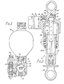
- FIG. 2 shows one of the rear suspension struts 6 in axial section.
- the strut comprises a lower piston portion 61 slidable in an upper, barrel assembly 62 (with appropriate sealing means S), both assemblies having eyes 63 and 64 for articulation to a swing axle and the vehicle structure respectively.
- the body 26a of the potentiometer 26 has its upper end secured in a recess in the barrel assembly 62 which is formed with a passage 65 for leadwires (not shown) for connecting the potentiometer 26 to the computer.
- the slider (not shown) within the casing 26a is connected by a rod 26b to the lower part of the plunger 61.
- the housing 26a carries a peg 66 which is clamped by a set screw 67.
- variable-volume chamber 8 within the strut 6 is connected by a transverse bore 68 both to a port 69 for connection to the lines 9 and 19, a pressure sensor (not shown) connected to the computer, and to the passage 36 which is here formed by an extension of the bore 68 and leads into the leveling control valve 35.
- the valve 35 is a series E050 minature proportional servo-valve supplied by Moog Controls Limited of Ashchurch, Tewksbury, GL20 8NA, England.
- the valve has a polarized torque motor which moves a pilot valve element between two opposed inlet pilot orifices to throttle the flow through one or other of these orifices.
- the resultant differentials in the back pressures in these orifices are applied to opposite ends of a hydraulic servo spool-valve controlling the flow to or from the passage 36.
- FIG. 3 shows a damper construction inserted between the line 19 and the gas spring 14 which is here in the form of a hydraulic pressure accumulator.
- the liquid port 71 is mounted in one end of a bore 72 extending through a damper housing 73 to a threaded connection 74 for the line 9.
- a disk-type damper valve 75 is slidable in an enlarged portion 76 of the bore 75 between two opposed shoulders.
- An adjustable throttle valve assembly 77 having an adjustable screw 78 with a conical end provides a preset flow resistance between passages 79 and 80 on opposite sides of the damper valve 75.
- a non return valve formed by a ball 81 allows flow through the valve 77 only in one direction.
- the resistance to flow in the opposite direction is independently adjustable by means of a similar assembly 82 connected in the opposite direction between the passages 79 and 80.
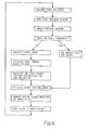
- Figure 4 shows a flow chart of the computing operations carried out by the computer.
Landscapes
- Engineering & Computer Science (AREA)
- Mechanical Engineering (AREA)
- Vehicle Body Suspensions (AREA)
Applications Claiming Priority (2)
| Application Number | Priority Date | Filing Date | Title |
|---|---|---|---|
| GB8710240 | 1987-04-30 | ||
| GB8710240A GB2204286B (en) | 1987-04-30 | 1987-04-30 | Vehicle suspension systems |
Publications (3)
| Publication Number | Publication Date |
|---|---|
| EP0289364A2 true EP0289364A2 (fr) | 1988-11-02 |
| EP0289364A3 EP0289364A3 (en) | 1990-02-07 |
| EP0289364B1 EP0289364B1 (fr) | 1992-07-29 |
Family
ID=10616614
Family Applications (1)
| Application Number | Title | Priority Date | Filing Date |
|---|---|---|---|
| EP88303978A Expired EP0289364B1 (fr) | 1987-04-30 | 1988-05-03 | Systèmes de suspension de véhicule |
Country Status (6)
| Country | Link |
|---|---|
| US (1) | US4861066A (fr) |
| EP (1) | EP0289364B1 (fr) |
| JP (1) | JPS6452521A (fr) |
| DE (1) | DE3873147T2 (fr) |
| ES (1) | ES2034215T3 (fr) |
| GB (1) | GB2204286B (fr) |
Cited By (1)
| Publication number | Priority date | Publication date | Assignee | Title |
|---|---|---|---|---|
| EP0328840A1 (fr) * | 1988-01-12 | 1989-08-23 | Automobiles Peugeot | Dispositif de suspension hydropneumatique semi-active et véhicule automobile équipé de ce dispositif |
Families Citing this family (5)
| Publication number | Priority date | Publication date | Assignee | Title |
|---|---|---|---|---|
| US5004264A (en) * | 1988-07-29 | 1991-04-02 | Nippondenso Co., Ltd. | Position control device and automotive suspension system employing same |
| AT394161B (de) * | 1990-01-24 | 1992-02-10 | Steyr Daimler Puch Ag | Vierraedriges kraftfahrzeug |
| US6220613B1 (en) | 1997-07-25 | 2001-04-24 | Actuant Corporation | Hydro-pneumatic vehicle suspension system |
| US6418360B1 (en) | 1999-01-08 | 2002-07-09 | Shockware | Sensor structure for measuring vehicle suspension related information |
| DE102018010153B4 (de) * | 2018-12-28 | 2021-10-28 | Bomag Gmbh | Baumaschine, insbesondere Straßenfräse, sowie Verfahren zur Steuerung der Hubposition einer Kolben-Zylinder-Einheit einer Hubsäule einer Baumaschine |
Family Cites Families (24)
| Publication number | Priority date | Publication date | Assignee | Title |
|---|---|---|---|---|
| FR1283959A (fr) * | 1960-12-28 | 1962-02-09 | Renault | Procédé et dispositif pour la correction de niveau et/ou d'assiette pour suspension pneumatique, en particulier hydropneumatique de véhicules |
| GB1174149A (en) * | 1967-08-16 | 1969-12-10 | Automotive Prod Co Ltd | Improvements in and relating to Suspension Systems for Vehicles |
| GB1197812A (en) * | 1968-01-15 | 1970-07-08 | Automotive Prod Co Ltd | Improvements in or relating to Vehicle Suspensions. |
| GB1396890A (en) * | 1971-07-09 | 1975-06-11 | Rover Co Ltd | Vehicle suspension systems |
| GB1419091A (en) * | 1972-02-21 | 1975-12-24 | Automotive Prod Co Ltd | Vehicle suspension systems |
| GB1384454A (en) * | 1972-03-08 | 1975-02-19 | Automotive Prod Co Ltd | Vehicle suspension |
| GB1367320A (en) * | 1972-07-19 | 1974-09-18 | Automotive Prod Co Ltd | Pneumatic suspension systems for vehicles |
| GB1450696A (en) * | 1973-11-08 | 1976-09-22 | Automotive Prod Co Ltd | Vehicle suspension systems |
| GB1484673A (en) * | 1973-11-28 | 1977-09-01 | Automotive Prod Co Ltd | Vehicle suspensions |
| GB1488254A (en) * | 1974-12-23 | 1977-10-12 | Automotive Prod Co Ltd | Vehicle suspensions |
| GB1466101A (en) * | 1975-08-26 | 1977-03-02 | Automotive Prod Co Ltd | Vehicle suspension |
| GB1587614A (en) * | 1976-12-01 | 1981-04-08 | Automotive Prod Co Ltd | Self-levelling vehicle suspension system |
| US4191274A (en) * | 1977-08-22 | 1980-03-04 | Spring Hill Laboratories, Inc. | Adjusting automobile suspension system |
| GB2025863B (en) * | 1978-06-08 | 1982-07-14 | Alfa Romeo Spa | Vehicle suspension systems |
| GB2097344B (en) * | 1981-04-08 | 1984-05-16 | Lucas Ind Plc | Self-leveling suspension system |
| FR2503641A1 (fr) * | 1981-04-10 | 1982-10-15 | Peugeot | Dispositif d'amortissement pour suspension de vehicule |
| US4468050A (en) * | 1983-08-15 | 1984-08-28 | Woods Lonnie K | Computer optimized adaptive suspension system |
| IT1164365B (it) * | 1983-08-04 | 1987-04-08 | Alfa Romeo Auto Spa | Dispositivo ammortizzatore delle oscillazioni per un autoveicolo |
| JPS6092914A (ja) * | 1983-10-27 | 1985-05-24 | Nippon Denso Co Ltd | 車高制御装置 |
| DE3414257C2 (de) * | 1984-04-14 | 1993-12-02 | Bosch Gmbh Robert | Federelement mit veränderbarer Härte für Fahrzeuge |
| GB8502135D0 (en) * | 1985-01-29 | 1985-02-27 | Lucas Ind Plc | Control system |
| JPS61175110A (ja) * | 1985-01-30 | 1986-08-06 | Nissan Motor Co Ltd | 車高調整装置 |
| JPS61184107A (ja) * | 1985-02-12 | 1986-08-16 | Mazda Motor Corp | 自動車の車高調整装置 |
| US4693493A (en) * | 1985-10-22 | 1987-09-15 | Toyota Jidosha Kabushiki Kaisha | System for vehicle body roll control utilizing steering angle detection |
-
1987
- 1987-04-30 GB GB8710240A patent/GB2204286B/en not_active Expired - Fee Related
-
1988
- 1988-04-28 JP JP63104382A patent/JPS6452521A/ja active Pending
- 1988-04-29 US US07/187,952 patent/US4861066A/en not_active Expired - Lifetime
- 1988-05-03 DE DE8888303978T patent/DE3873147T2/de not_active Expired - Fee Related
- 1988-05-03 ES ES198888303978T patent/ES2034215T3/es not_active Expired - Lifetime
- 1988-05-03 EP EP88303978A patent/EP0289364B1/fr not_active Expired
Cited By (1)
| Publication number | Priority date | Publication date | Assignee | Title |
|---|---|---|---|---|
| EP0328840A1 (fr) * | 1988-01-12 | 1989-08-23 | Automobiles Peugeot | Dispositif de suspension hydropneumatique semi-active et véhicule automobile équipé de ce dispositif |
Also Published As
| Publication number | Publication date |
|---|---|
| JPS6452521A (en) | 1989-02-28 |
| DE3873147D1 (de) | 1992-09-03 |
| GB2204286A (en) | 1988-11-09 |
| ES2034215T3 (es) | 1993-04-01 |
| DE3873147T2 (de) | 1993-03-18 |
| GB8710240D0 (en) | 1987-06-03 |
| GB2204286B (en) | 1991-02-06 |
| EP0289364A3 (en) | 1990-02-07 |
| EP0289364B1 (fr) | 1992-07-29 |
| US4861066A (en) | 1989-08-29 |
Similar Documents
| Publication | Publication Date | Title |
|---|---|---|
| US6264212B1 (en) | Vehicle suspension system | |
| US5562305A (en) | Vehicle suspension system | |
| EP0599882B1 (fr) | Suspension de vehicule | |
| US4700972A (en) | Computerized, central hydraulic, electronic variable suspension | |
| US4468050A (en) | Computer optimized adaptive suspension system | |
| US2757376A (en) | Autoamtic load responsive suspension for vehicles | |
| CA1102829A (fr) | Traduction non-disponible | |
| US5601307A (en) | Vehicle suspension system | |
| US4468739A (en) | Computer optimized adaptive suspension system having combined shock absorber/air spring unit | |
| US7637513B2 (en) | Vehicle suspension system | |
| US4607861A (en) | Hydraulic stabilizing system for vehicle suspension | |
| GB2309205A (en) | Active roll control | |
| US4826206A (en) | Tension actuator load suspension system | |
| EP0493490A4 (en) | Interconnected fluid suspension for vehicles | |
| WO1995011814A1 (fr) | Dispositif de suspension de vehicule | |
| EP0289364B1 (fr) | Systèmes de suspension de véhicule | |
| US3836166A (en) | Pneumatic suspension systems for vehicles | |
| GB1496430A (en) | Vehicle suspension system | |
| EP0387269B1 (fr) | Systemes de suspension pour vehicule | |
| US5110152A (en) | Active suspension system | |
| JPH0490917A (ja) | ハイドロニューマチックサスペンション装置 | |
| JPH0314715A (ja) | 車輌懸架系 | |
| GB2337730A (en) | An active vehicle anti-roll apparatus | |
| JP2625164B2 (ja) | 車両用アンチローリング装置 | |
| IE990714A1 (en) | Vehicle suspension system |
Legal Events
| Date | Code | Title | Description |
|---|---|---|---|
| PUAI | Public reference made under article 153(3) epc to a published international application that has entered the european phase |
Free format text: ORIGINAL CODE: 0009012 |
|
| AK | Designated contracting states |
Kind code of ref document: A2 Designated state(s): DE ES FR GB IT SE |
|
| PUAL | Search report despatched |
Free format text: ORIGINAL CODE: 0009013 |
|
| AK | Designated contracting states |
Kind code of ref document: A3 Designated state(s): DE ES FR GB IT SE |
|
| 17P | Request for examination filed |
Effective date: 19900316 |
|
| 17Q | First examination report despatched |
Effective date: 19910805 |
|
| GRAA | (expected) grant |
Free format text: ORIGINAL CODE: 0009210 |
|
| AK | Designated contracting states |
Kind code of ref document: B1 Designated state(s): DE ES FR GB IT SE |
|
| REF | Corresponds to: |
Ref document number: 3873147 Country of ref document: DE Date of ref document: 19920903 |
|
| ITF | It: translation for a ep patent filed | ||
| ET | Fr: translation filed | ||
| REG | Reference to a national code |
Ref country code: ES Ref legal event code: FG2A Ref document number: 2034215 Country of ref document: ES Kind code of ref document: T3 |
|
| PLBE | No opposition filed within time limit |
Free format text: ORIGINAL CODE: 0009261 |
|
| STAA | Information on the status of an ep patent application or granted ep patent |
Free format text: STATUS: NO OPPOSITION FILED WITHIN TIME LIMIT |
|
| 26N | No opposition filed | ||
| EAL | Se: european patent in force in sweden |
Ref document number: 88303978.6 |
|
| REG | Reference to a national code |
Ref country code: GB Ref legal event code: IF02 |
|
| PGFP | Annual fee paid to national office [announced via postgrant information from national office to epo] |
Ref country code: GB Payment date: 20040428 Year of fee payment: 17 |
|
| PGFP | Annual fee paid to national office [announced via postgrant information from national office to epo] |
Ref country code: SE Payment date: 20040506 Year of fee payment: 17 |
|
| PGFP | Annual fee paid to national office [announced via postgrant information from national office to epo] |
Ref country code: FR Payment date: 20040510 Year of fee payment: 17 |
|
| PGFP | Annual fee paid to national office [announced via postgrant information from national office to epo] |
Ref country code: DE Payment date: 20040513 Year of fee payment: 17 |
|
| PGFP | Annual fee paid to national office [announced via postgrant information from national office to epo] |
Ref country code: ES Payment date: 20040518 Year of fee payment: 17 |
|
| PG25 | Lapsed in a contracting state [announced via postgrant information from national office to epo] |
Ref country code: IT Free format text: LAPSE BECAUSE OF NON-PAYMENT OF DUE FEES Effective date: 20050503 Ref country code: GB Free format text: LAPSE BECAUSE OF NON-PAYMENT OF DUE FEES Effective date: 20050503 |
|
| PG25 | Lapsed in a contracting state [announced via postgrant information from national office to epo] |
Ref country code: SE Free format text: LAPSE BECAUSE OF NON-PAYMENT OF DUE FEES Effective date: 20050504 Ref country code: ES Free format text: LAPSE BECAUSE OF NON-PAYMENT OF DUE FEES Effective date: 20050504 |
|
| PG25 | Lapsed in a contracting state [announced via postgrant information from national office to epo] |
Ref country code: DE Free format text: LAPSE BECAUSE OF NON-PAYMENT OF DUE FEES Effective date: 20051201 |
|
| EUG | Se: european patent has lapsed | ||
| GBPC | Gb: european patent ceased through non-payment of renewal fee |
Effective date: 20050503 |
|
| PG25 | Lapsed in a contracting state [announced via postgrant information from national office to epo] |
Ref country code: FR Free format text: LAPSE BECAUSE OF NON-PAYMENT OF DUE FEES Effective date: 20060131 |
|
| REG | Reference to a national code |
Ref country code: FR Ref legal event code: ST Effective date: 20060131 |
|
| REG | Reference to a national code |
Ref country code: ES Ref legal event code: FD2A Effective date: 20050504 |