EP0289480A2 - Vorrichtung zur Herstellung einer feuerfesten Auskleidung auf der Innenwand eines metallurgischen Gefässes - Google Patents
Vorrichtung zur Herstellung einer feuerfesten Auskleidung auf der Innenwand eines metallurgischen Gefässes Download PDFInfo
- Publication number
- EP0289480A2 EP0289480A2 EP88870071A EP88870071A EP0289480A2 EP 0289480 A2 EP0289480 A2 EP 0289480A2 EP 88870071 A EP88870071 A EP 88870071A EP 88870071 A EP88870071 A EP 88870071A EP 0289480 A2 EP0289480 A2 EP 0289480A2
- Authority
- EP
- European Patent Office
- Prior art keywords
- lance
- carriage
- degrees
- longitudinal axis
- raceway
- Prior art date
- Legal status (The legal status is an assumption and is not a legal conclusion. Google has not performed a legal analysis and makes no representation as to the accuracy of the status listed.)
- Withdrawn
Links
Images

Classifications
-
- B—PERFORMING OPERATIONS; TRANSPORTING
- B22—CASTING; POWDER METALLURGY
- B22D—CASTING OF METALS; CASTING OF OTHER SUBSTANCES BY THE SAME PROCESSES OR DEVICES
- B22D41/00—Casting melt-holding vessels, e.g. ladles, tundishes, cups or the like
- B22D41/02—Linings
- B22D41/023—Apparatus used for making or repairing linings
Definitions
- the present invention relates to a device for depositing a protective coating on the inner wall of a metallurgical vessel.
- This invention relates more particularly to continuous casting distribution baskets, which generally consist of a metal carcass internally covered with a permanent refractory lining.
- This permanent lining is itself covered with a protective coating intended to ensure its protection against the physical and chemical stresses to which it is exposed.
- Patent BE-A-891,980 discloses a process for depositing by spraying (hot gunning) a protective coating of the aforementioned type in a distribution basket for continuous casting.
- the object of the present invention is to propose a device allowing the economical implementation of this method of gunning, particularly in the case of a metallurgical container provided with a cover, such as for example a basket for distributing continuous casting.
- said first carriage comprises means for ensuring the tilting of the metallurgical container around a horizontal axis substantially parallel to the direction of translation of the first carriage.
- said first carriage comprises means for pivoting said metallurgical container around a substantially vertical axis.
- the projection lance comprises a rectilinear tubular portion which is provided, at its end directed towards said first carriage, with means for deflecting the materials projected from a certain angle relative to the longitudinal axis of said tubular portion straight.
- said deflection means consist of a rectilinear tubular section fixed with respect to said rectilinear tubular portion and whose longitudinal axis forms, with the longitudinal axis of said rectilinear tubular portion, an angle between 5 degrees and 30 degrees, and preferably essentially equal to 15 degrees.
- said deflection means consist of a rectilinear tubular section articulated to said rectilinear tubular portion and orientable by an angle variable between 0 degrees and 30 degrees in any plane passing through the longitudinal axis of said rectilinear tubular portion .
- the means for rotating the lance around its longitudinal axis comprise a motor and at least one switch system arranged so as to impart to the lance an alternating axial rotation movement of an amplitude less than 360 degrees.
- the means for pivoting said lance also comprise a motor and at least one switch system arranged so as to impart to the lance an alternating transverse pivoting movement of an amplitude less than 360 degrees .
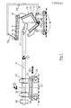
- a distributor basket 10 for continuous casting is provided with a cover 11 intended to limit the heat losses by radiation.
- the distributor basket 10 consists of a metal carcass 12 and a permanent lining 13, the latter itself having to be covered with a protective coating, not shown in FIG. 1.
- the cover 11 comprises a metal support 14 provided with an interior refractory lining 15; there is normally no protective coating provided on the inner lining of the cover 11, since the latter is not subjected to the physical and chemical stresses applied by the liquid steel and slag. The presence and the installation of such a protective coating on the interior lining of the cover 11 are not however incompatible with the present invention.
- the cover 11 is fixed to the distribution basket 10 by two articulations 16, 17 situated on opposite edges of the basket; the basket-lid assembly can therefore be opened on either side, depending on the edge of the lid that is lifted.
- the distributor basket 10, provided with its cover 11, is placed on a first carriage 18, which can move in translation on a raceway 19, in the direction perpendicular to the plane of the drawing and shown by the arrows 1.
- the basket 10 is shown in an inclined position to the left, with its cover 11 raised by rotation around the articulation 16.
- the basket can be rotated 180 degrees around a substantially vertical axis; this movement, symbolized by the arrow 5, is carried out in combination with a change of the opening side of the basket to ensure the treatment of the entire interior surface of the basket 10.
- a second carriage 20, carrying a gunning lance 21, can move in translation on a second raceway 22 in a direction, symbolized by the arrow 4, substantially perpendicular to that of the movement of the first carriage 18.
- the length of the lance 21 and the relative arrangement of the tracks 19, 22 and the carriages 18, 20 are such that the end of the lance 21 can enter or leave the basket 10 by simple translation of the second carriage 20.
- the lance 21 is supported in bearings 23, 24 mounted on a plate 25 disposed on the carriage 20. This plate 25 can rotate around a substantially vertical axis along arrow 3, by means of a circular raceway shown diagrammatically by rollers 26.
- the lance 21 can rotate, in the bearings 23, 24, around its longitudinal axis along arrow 2.
- the lance 21 carries, at its end directed towards the basket 10, a rectilinear tubular section 27 inclined at an angle ⁇ between 5 degrees and 30 degrees relative to the longitudinal axis of the lance 21.
- the lance 21 carries a counterweight 28 intended in particular to ensure the balance of the carriage 20.
- Fig. 2 illustrates, in a schematic perspective view, the relative position and the relative movements of the lance 21 and of the basket 10. It clearly shows that the gunning of all the walls of the distributor basket can be carried out by means of the combination of simple movements symbolized by arrows 1 to 5.
- the rotation of the lance 21 around its longitudinal axis allows, thanks to the bent end 27, to vertically move the impact zone of the gunning.
- the 180-degree rotation of the basket around a vertical axis makes it possible to reach any point on the interior wall of the basket 10, regardless of the depth thereof.
- the device of the invention is also advantageous for the device of the invention to be equipped with means for lifting the cover of the metallurgical container in which it is desired to deposit by projection a refractory protective lining.
- These means advantageously include a device for adjusting the degree of opening of this cover, in order to guarantee the best possible access for the spray lance without unacceptably reducing the action of the cover in terms of limiting thermal losses by radiation.
- These means consist for example of a bracket 29 fixed to the first carriage 18 and a jack 30 articulated on the one hand to said bracket and hung on the other hand at the end of the cover 11 to be lifted.
- the device of the invention also makes it possible to treat any other type of metallurgical container, such as a ladle.
Landscapes
- Engineering & Computer Science (AREA)
- Mechanical Engineering (AREA)
- Furnace Housings, Linings, Walls, And Ceilings (AREA)
- Treatment Of Steel In Its Molten State (AREA)
Applications Claiming Priority (2)
| Application Number | Priority Date | Filing Date | Title |
|---|---|---|---|
| BE8700471 | 1987-04-30 | ||
| BE8700471A BE1000516A6 (fr) | 1987-04-30 | 1987-04-30 | Dispositif pour deposer un revetement protecteur sur la paroi interieure d'un recipient metallurgique. |
Publications (2)
| Publication Number | Publication Date |
|---|---|
| EP0289480A2 true EP0289480A2 (de) | 1988-11-02 |
| EP0289480A3 EP0289480A3 (de) | 1989-10-04 |
Family
ID=3882633
Family Applications (1)
| Application Number | Title | Priority Date | Filing Date |
|---|---|---|---|
| EP88870071A Withdrawn EP0289480A3 (de) | 1987-04-30 | 1988-04-27 | Vorrichtung zur Herstellung einer feuerfesten Auskleidung auf der Innenwand eines metallurgischen Gefässes |
Country Status (2)
| Country | Link |
|---|---|
| EP (1) | EP0289480A3 (de) |
| BE (1) | BE1000516A6 (de) |
Cited By (2)
| Publication number | Priority date | Publication date | Assignee | Title |
|---|---|---|---|---|
| WO1990012666A1 (fr) * | 1989-04-26 | 1990-11-01 | Daussan Et Compagnie | Procede et installation pour realiser un revetement sur les parois interieures d'un recipient metallurgique |
| EP0976478A4 (de) * | 1997-11-25 | 2001-11-07 | Shinagawa Refractories Co | Vorrichtung zum speichern von ungebranntem feuerfestem erzeugnis |
Family Cites Families (3)
| Publication number | Priority date | Publication date | Assignee | Title |
|---|---|---|---|---|
| JPS5479104A (en) * | 1977-12-08 | 1979-06-23 | Kurosaki Refractories Co | Lining apparatus equipped with television camera |
| DE2851259C3 (de) * | 1978-10-13 | 1981-10-01 | Spribag Ag, Widen-Mutschellen | Spritzanlage zur Heißreparatur von metallurgischen Gefäßen |
| BE891980A (fr) * | 1982-02-01 | 1982-05-27 | Centre Rech Metallurgique | Procede pour deposer un revetement protecteur sur la paroi interieure d'un panier repartiteur de coulee continue |
-
1987
- 1987-04-30 BE BE8700471A patent/BE1000516A6/fr not_active IP Right Cessation
-
1988
- 1988-04-27 EP EP88870071A patent/EP0289480A3/de not_active Withdrawn
Cited By (5)
| Publication number | Priority date | Publication date | Assignee | Title |
|---|---|---|---|---|
| WO1990012666A1 (fr) * | 1989-04-26 | 1990-11-01 | Daussan Et Compagnie | Procede et installation pour realiser un revetement sur les parois interieures d'un recipient metallurgique |
| FR2646367A1 (fr) * | 1989-04-26 | 1990-11-02 | Daussan & Co | Procede et installation pour realiser un revetement sur les parois interieures d'un recipient metallurgique |
| AU627585B2 (en) * | 1989-04-26 | 1992-08-27 | Daussan Et Compagnie | Production of a monolithic lining in a ladle |
| US5160692A (en) * | 1989-04-26 | 1992-11-03 | Daussan Et Compagnie | Process and plant for producing a lining on the inner walls of a metallurgical vessel |
| EP0976478A4 (de) * | 1997-11-25 | 2001-11-07 | Shinagawa Refractories Co | Vorrichtung zum speichern von ungebranntem feuerfestem erzeugnis |
Also Published As
| Publication number | Publication date |
|---|---|
| EP0289480A3 (de) | 1989-10-04 |
| BE1000516A6 (fr) | 1989-01-10 |
Similar Documents
| Publication | Publication Date | Title |
|---|---|---|
| EP3449029B1 (de) | Vorrichtung zur kontinuierlichen heisstauchbeschichtung eines metallbandes und zugehöriges verfahren | |
| BE1004322A3 (fr) | Dispositif de manutention d'une goulotte de distribution d'un four a cuve et mecanisme d'entrainement adapte a ce dispositif. | |
| EP0220543B1 (de) | Vorrichtung zum Zustellen der Wände eines Bauwerkes | |
| EP3449030B2 (de) | Vorrichtung zur kontinuierlichen schmelztauchbeschichtung eines metallbandes und zugehöriges verfahren | |
| LU86272A1 (fr) | Installation automatisee pour briqueter la paroi interieure d'une enceint | |
| EP1129221B1 (de) | Verteilerschurre für schüttgut | |
| EP0289480A2 (de) | Vorrichtung zur Herstellung einer feuerfesten Auskleidung auf der Innenwand eines metallurgischen Gefässes | |
| EP0078760B1 (de) | Veränderbare Giessöffnung | |
| EP0672806A1 (de) | Schalungsvorrichtung und Verfahren zur Anwendung | |
| EP0079290A1 (de) | Vorrichtung zum Temperaturmessen und/oder Probenehmen bei einer Frischeinrichtung | |
| EP3179194B1 (de) | Haltevorrichtung einer granate für artilleriewaffe | |
| EP0213042A2 (de) | Vorrichtung zum Schutz eines flüssigen Giesstrahls gegen Oxydation und/oder Nitrierung | |
| WO2006016202A1 (fr) | Lame de decrassage de reacteur metallurgique | |
| EP0160593A1 (de) | Vorrichtung zur Handhabung eines Schutzrohres für einen Giessstrahl | |
| BE1011299A6 (fr) | Appareil de manutention automatique d'un tube de coulee. | |
| EP0226576B1 (de) | Ausrüstung zur wiederherstellung und zur reparatur von hochöfen | |
| EP0844310B1 (de) | Schlackenabstreifanlage für die Rüssel eines Vakuumbehandlungsgefässes für Stahlschmelzen | |
| EP0128136A1 (de) | Verfahren und vorrichtung zum auskleiden von gefässen, insbesondere gefässen der metallurgie | |
| EP0064418B1 (de) | Einrichtung zur Stahlherstellung, bestehend aus einem Konverter, einer Abgashaube und einer Sauerstofflanze | |
| BE566916A (de) | ||
| EP0424346B1 (de) | Vorrichtung zum kontinuierlichen Messen der Temperatur eines Metallbades und deren Anwendungsverfahren | |
| FR2627510A1 (fr) | Convertisseur d'elaboration de metal | |
| FR2650851A1 (fr) | Console a angle variable, notamment pour l'industrie du batiment | |
| FR2503737A1 (fr) | Installation de production d'acier comportant un convertisseur, une hotte et une lance de soufflage | |
| EP0954615A1 (de) | Verfahren und vorrichtung zur pfannenbehandlung von stahl |
Legal Events
| Date | Code | Title | Description |
|---|---|---|---|
| PUAI | Public reference made under article 153(3) epc to a published international application that has entered the european phase |
Free format text: ORIGINAL CODE: 0009012 |
|
| AK | Designated contracting states |
Kind code of ref document: A2 Designated state(s): AT DE FR GB IT LU SE |
|
| PUAL | Search report despatched |
Free format text: ORIGINAL CODE: 0009013 |
|
| AK | Designated contracting states |
Kind code of ref document: A3 Designated state(s): AT DE FR GB IT LU SE |
|
| STAA | Information on the status of an ep patent application or granted ep patent |
Free format text: STATUS: THE APPLICATION IS DEEMED TO BE WITHDRAWN |
|
| 18D | Application deemed to be withdrawn |
Effective date: 19900405 |