EP0289514B1 - Anordnung zum verdichten von haushaltsabfällen - Google Patents
Anordnung zum verdichten von haushaltsabfällen Download PDFInfo
- Publication number
- EP0289514B1 EP0289514B1 EP87900910A EP87900910A EP0289514B1 EP 0289514 B1 EP0289514 B1 EP 0289514B1 EP 87900910 A EP87900910 A EP 87900910A EP 87900910 A EP87900910 A EP 87900910A EP 0289514 B1 EP0289514 B1 EP 0289514B1
- Authority
- EP
- European Patent Office
- Prior art keywords
- compressing
- container
- unit
- arrangement
- arrangement according
- Prior art date
- Legal status (The legal status is an assumption and is not a legal conclusion. Google has not performed a legal analysis and makes no representation as to the accuracy of the status listed.)
- Expired - Lifetime
Links
Images


Classifications
-
- B—PERFORMING OPERATIONS; TRANSPORTING
- B30—PRESSES
- B30B—PRESSES IN GENERAL
- B30B9/00—Presses specially adapted for particular purposes
- B30B9/30—Presses specially adapted for particular purposes for baling; Compression boxes therefor
- B30B9/3082—Presses specially adapted for particular purposes for baling; Compression boxes therefor with compression means other than rams performing a rectilinear movement
Definitions
- the present invention relates to an arrangement for the compressing of refuse and similar material by means of a roller-shape self-propelled compressing body acting in a container or similar receptacle and moving along the container so as to compress the material.
- a roller-shape self-propelled compressing body acting in a container or similar receptacle and moving along the container so as to compress the material.
- Such a device is known by PE-A-3 406 879.
- the principal object of the present invention is, in the first place, to make available an arrangment of the kind referred to above which more effectively compress material of varying kinds without the need for a major labour input.
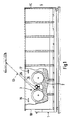
- an arrangement 3 in accordance with the present invention is intended to be capable of acting in such a way as to break up and compress the material 2 effectively, thus enabling a large quantity of material 2 to be contained therein.
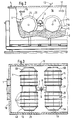
- the arrangement 3 comprises a number of roller-shaped compressing bodies 4, 5 connected together to form a unit which is so arranged as to be self-propelled and to be freely accommodated inside the container 1 in question and to be controlled from the outside 6 of the container.
- Two compressing bodies 4, 5 are appropriately connected together via, for example, a connecting tube 7, 8 or some other suitable connecting device extending radially from each compressing body 4, 5, which tubes are connected to one another via a link 9, 10, which can be rigid or fixed, as in the first embodiment illustrated, or which can be moving, as illustrated in fig. 6, for example.
- a drive motor 11 with a gearbox 12 attached to it can be enclosed within each compressing body 41, 51, as shown in Fig. 5 in the second embodiment of an arrangement 31.
- a connection 13 which can consist of an electric cable mounted on a cable drum, or some other suitable connection for transmitting energy and/or drive information to the unit 3, can be capable of connection to the unit and can be so installed as to be connected to the outside 6 of the container.
- Drive information to the unit 3 can be transmitted from a control panel situated at a certain distance from the inside 1A of the container, which control panel can include a control for starting and stopping the arrangement and a control for actuating the time relay for the purpose of setting the desired period for which the arrangement 3 is to operate inside the container 1 or the period after which it shall change direction, depending on the length of the container.
- the aforementioned compressing bodies 4, 5 and 41, 51 are provided with devices 14, 15 which are so arranged as to be capable of breaking up material 2, such as household and/or industrial refuse containing paper, wood, plastic and metal, etc., for the period during which the compressing bodies 4, 5; 41, 51 are caused to rotate in the direction 16, 17 in which the arrangement 3; 31 is intended to move inside the container.
- the aforementioned devices 14 for breaking up the material can consist of several annular knives which are attached to, for example, a preferably polygonal core 18 in the compressing body 4, 5 and are distributed along the axis of rotation 19 of the body, as illustrated in Fig. 3, for example.
- the knives 14 can exhibit a width such that they extend beyond the boundary edge of the core, measured in the radial sense, or essentially reach as far as the aforementioned boundary edge of the core 18.
- the aforementioned polygonal core 18, which in the illustrated embodiment exhibits eight lateral edges 20, but which can exhibit four, six or more lateral edges, is so arranged as to compact the material 2 which has been broken up by the knives 14, at the same time as the arrangement is caused to move inside the container 1 between the boundary halls 1B, 1C of the container by the rotation of the compressing bodies 4, 5; 41, 51.
- the aforementioned lateral edges 20 of the body and the edges 21 which are situated between the edges and extend across the direction of travel press the material 2 into a compressed, compact mass, which exhibits high density, and constitute the equivalent of running wheels for the arrangement as the arrangement 3 is caused by its own power to move freely inside the container 1 between the aforementioned walls 1B, 1C.
- the core 181 can also exhibit cylindrical form, as shown in Figs. 4 and 5, in which case consideration may be given to the possibility either of providing helical cutting devices 15 extending, for example, radially outwards from the core along its external surface 181A, in addition to the knives of the kind described above, or of providing such cutting devices 15 on their own.
- the aforementioned cutting devices 15 can be strip-shaped and can be so arranged as to extend between the ends 22, 23 and the central part 24 of the compressing body, and can be attached by welding, for example.
- the form of these cutting devices 15 may vary, although their function at all times remains to cut off portions from the intended material 2 and to grind this down, and then to compress the material into a compact mass.
- the cutting devices 15 can exhibit a cutting edge 15A on at least one of their lateral edge surfaces 15B, 15C.
- the compressing bodies 4, 5; 41, 51 can be provided at each of their ends 4A, 4B, 5A, 5B; 41A, 41B, 51A, 51B with suitable, easily replaced guards 25, for example a shock-absorbing disc consisting of a flexible material, which are so arranged as to be capable of interacting with each of the side walls 1D, 1E of the container when the unit 1 approaches too close to these and when the bodies arrive at the walls 1D, 1E. Thanks to the compressibility of the guards 25, impacts are absorbed effectively by them.
- guards 25 for example a shock-absorbing disc consisting of a flexible material
- means for sensing the position of the arrangement can be provided, for example in the form of a safety system controlled by an IR photo-cell and a logic relay system.
- the unit 3 can be raised by means of a hoist, for example, after having been attached to the lifting hook via an eye 26 on the unit 3, and can be lowered into a container with the bodies 4, 5 held in the position illustrated in Fig. 3.
- the arrangement 3 is caused to move forwards and backwards inside the container 1, in conjunction with which, at the same time as it breaks up the material 2 and compresses it, it also packs down the material so as to permit the effective filling of the container to its maximum level.
- the appropriate kind of compressing bodies 4, 5; 41, 51 and devices 14, 15 for breaking up the material can be fitted, depending on the composition of the material.
- the unit 3 is stopped after a pre-set period or by manual actuation of the drive and control devices of the unit when material is no longer being filled into the container, and is subsequently restarted as the need arises.
- the time relay control system which can be adjusted according to the length of the container, determines the running time of the unit in each direction 16, 17 before the unit 3 is automatically caused to change its direction of travel so as to move in the opposite direction.
- the unit 3 can be lifted down from the container 1 for use in an unfilled container.
- the moving link 10 as shown in Fig. 6, amongst others, consists of discs 27, 28 accommodated between two body arms 71, 81, which discs are secured by means of bolts 29 to the respective body arms 71, 81 and are connected to one another via a rod 30 and a nut 31 in such a way as to be free to move.
- This link permits the bodies to rotate relative to one another about the axis 32 of the link in the direction of the arrow 33.
Landscapes
- Engineering & Computer Science (AREA)
- Mechanical Engineering (AREA)
- Refuse Collection And Transfer (AREA)
Claims (10)
Priority Applications (1)
| Application Number | Priority Date | Filing Date | Title |
|---|---|---|---|
| AT87900910T ATE64353T1 (de) | 1986-01-23 | 1987-01-19 | Anordnung zum verdichten von haushaltsabfaellen. |
Applications Claiming Priority (2)
| Application Number | Priority Date | Filing Date | Title |
|---|---|---|---|
| SE8600296A SE456737B (sv) | 1986-01-23 | 1986-01-23 | Anordning foer komprimering av avfall |
| SE8600296 | 1986-01-23 |
Publications (2)
| Publication Number | Publication Date |
|---|---|
| EP0289514A1 EP0289514A1 (de) | 1988-11-09 |
| EP0289514B1 true EP0289514B1 (de) | 1991-06-12 |
Family
ID=20363197
Family Applications (1)
| Application Number | Title | Priority Date | Filing Date |
|---|---|---|---|
| EP87900910A Expired - Lifetime EP0289514B1 (de) | 1986-01-23 | 1987-01-19 | Anordnung zum verdichten von haushaltsabfällen |
Country Status (6)
| Country | Link |
|---|---|
| US (1) | US4960045A (de) |
| EP (1) | EP0289514B1 (de) |
| AU (1) | AU6897387A (de) |
| ES (1) | ES2003663A6 (de) |
| SE (1) | SE456737B (de) |
| WO (1) | WO1987004409A1 (de) |
Families Citing this family (5)
| Publication number | Priority date | Publication date | Assignee | Title |
|---|---|---|---|---|
| AUPN446595A0 (en) * | 1995-07-31 | 1995-08-24 | Hewitt, Geoffrey John | Cotton module builder assembly |
| AU686952B2 (en) * | 1995-07-31 | 1998-02-12 | G.T. Enterprises Pty Ltd | Cotton module builder assembly |
| GB2510541A (en) * | 2014-05-26 | 2014-08-06 | Carl Matthew Hughes | Waste crushing systems |
| US11839880B1 (en) * | 2021-01-29 | 2023-12-12 | Daniel L. Dillon | Mobile trash compactor and pulverizer |
| CN113230067B (zh) * | 2021-04-29 | 2022-11-18 | 宿州市久协医药信息咨询有限公司 | 一种儿科用配药推车 |
Family Cites Families (14)
| Publication number | Priority date | Publication date | Assignee | Title |
|---|---|---|---|---|
| US1394580A (en) * | 1919-04-11 | 1921-10-25 | Glenn N Rager | Compressing mechanism |
| US2832574A (en) * | 1956-02-01 | 1958-04-29 | Armstrong Cork Co | Tumbler for mixing plastic composition |
| US3069742A (en) * | 1956-07-21 | 1962-12-25 | Walchhuetter Ulrico | Electric and electronic circuits for controlling friction presses |
| FR1181358A (fr) * | 1956-08-20 | 1959-06-15 | Presse, en particulier pour silos à fourrage | |
| US3011430A (en) * | 1959-02-02 | 1961-12-05 | Bloomquist Machine Mfg Company | Orange juice extractor |
| DE1175028B (de) * | 1961-10-24 | 1964-07-30 | Peter Mario Amann | Vorrichtung zum Walzen von Gaerfutter |
| AT258801B (de) * | 1966-02-21 | 1967-12-11 | Friedrich Jaroschik | Vorrichtung zum Pressen des Gutes in Flachsilos |
| GB1597948A (en) * | 1976-09-18 | 1981-09-16 | Cincinnati Milacron Inc | Power press provided with a contactless switch |
| FI56873C (fi) * | 1978-08-25 | 1980-04-10 | Matti Sakari Sinkkonen | Med formkuggar foersedd valskonstruktion foer avfallskrossanordning avsedd foer avstjaelpningsplatser |
| DE3166299D1 (en) * | 1980-06-24 | 1984-10-31 | Heinz Bergmann | Device to compact refuse in open containers |
| DE3326007A1 (de) * | 1982-10-15 | 1984-04-19 | Heinz 4474 Lathen Bergmann | Vorrichtung zum verdichten von aus verpackungsmaterial und leicht pressbaren abfaellen bestehenden muell |
| US4530620A (en) * | 1983-02-17 | 1985-07-23 | Bernard Mccartney Limited | Landfill compactor vehicles |
| DE3406879A1 (de) * | 1984-02-25 | 1985-08-29 | Heinz 4474 Lathen Bergmann | Vorrichtung zum verdichten von aus verpackungsmaterial und leicht pressbaren abfaellen bestehendem muell |
| FI842678A7 (fi) * | 1984-07-04 | 1986-01-05 | Tana Jyrae Ky | Foerfarande foer framstaellning av vaeltar samt vaeltar och vaeltserie framstaellda medelst foerfarandet. |
-
1986
- 1986-01-23 SE SE8600296A patent/SE456737B/sv not_active IP Right Cessation
-
1987
- 1987-01-19 AU AU68973/87A patent/AU6897387A/en not_active Abandoned
- 1987-01-19 EP EP87900910A patent/EP0289514B1/de not_active Expired - Lifetime
- 1987-01-19 WO PCT/SE1987/000018 patent/WO1987004409A1/en not_active Ceased
- 1987-01-23 ES ES8700172A patent/ES2003663A6/es not_active Expired
-
1989
- 1989-11-27 US US07/443,050 patent/US4960045A/en not_active Expired - Fee Related
Also Published As
| Publication number | Publication date |
|---|---|
| SE8600296L (sv) | 1987-07-24 |
| WO1987004409A1 (en) | 1987-07-30 |
| AU6897387A (en) | 1987-08-14 |
| SE456737B (sv) | 1988-10-31 |
| ES2003663A6 (es) | 1988-11-01 |
| US4960045A (en) | 1990-10-02 |
| SE8600296D0 (sv) | 1986-01-23 |
| EP0289514A1 (de) | 1988-11-09 |
Similar Documents
| Publication | Publication Date | Title |
|---|---|---|
| EP0289514B1 (de) | Anordnung zum verdichten von haushaltsabfällen | |
| US5277014A (en) | Bag discharge station | |
| US2691338A (en) | Paper shredding and baling machine | |
| US5584762A (en) | Apparatus and method for compacting cotton materials in a basket | |
| US3527161A (en) | Refuse compactor apparatus | |
| US3893386A (en) | Box baling machine and cart | |
| US3720844A (en) | Control circuit for trash compactor | |
| EP1940706B1 (de) | Abfallbehälter mit verdichtungsmitteln | |
| CN210545603U (zh) | 一种玻璃回收破碎设备 | |
| JPH05505558A (ja) | 物体を破砕する装置 | |
| US3903461A (en) | Electrical circuitry for refuse compactor | |
| US3254777A (en) | Silo unloader | |
| US2888253A (en) | Silo unloader having wall cleaning means | |
| US6588330B1 (en) | Trash compactor system | |
| US4155297A (en) | Self-packing container | |
| CN110332550A (zh) | 一种危险废物焚烧线的炉渣回收装置 | |
| EP0618863B1 (de) | Müllpresse. | |
| US6520072B2 (en) | Waste compacting method and machine | |
| CN107638927A (zh) | 一种废旧纸箱的回收粉碎装置 | |
| JP3294719B2 (ja) | 破砕機の駆動装置 | |
| SU1590418A1 (ru) | Устройство дл уплотнени мусора в контейнерах | |
| WO2006010789A1 (en) | Waste press device | |
| CN211491822U (zh) | 纸质品生产用具备保护功能的切纸机 | |
| US6684762B1 (en) | Method of reducing the volume of empty packaging and compression device for empty packaging | |
| US3911810A (en) | Baling machine |
Legal Events
| Date | Code | Title | Description |
|---|---|---|---|
| PUAI | Public reference made under article 153(3) epc to a published international application that has entered the european phase |
Free format text: ORIGINAL CODE: 0009012 |
|
| 17P | Request for examination filed |
Effective date: 19880707 |
|
| AK | Designated contracting states |
Kind code of ref document: A1 Designated state(s): AT BE CH DE FR GB IT LI LU NL SE |
|
| 17Q | First examination report despatched |
Effective date: 19900420 |
|
| GRAA | (expected) grant |
Free format text: ORIGINAL CODE: 0009210 |
|
| AK | Designated contracting states |
Kind code of ref document: B1 Designated state(s): AT BE CH DE FR GB IT LI LU NL SE |
|
| PG25 | Lapsed in a contracting state [announced via postgrant information from national office to epo] |
Ref country code: SE Effective date: 19910612 Ref country code: NL Effective date: 19910612 Ref country code: BE Effective date: 19910612 Ref country code: IT Free format text: LAPSE BECAUSE OF FAILURE TO SUBMIT A TRANSLATION OF THE DESCRIPTION OR TO PAY THE FEE WITHIN THE PRE;WARNING: LAPSES OF ITALIAN PATENTS WITH EFFECTIVE DATE BEFORE 2007 MAY HAVE OCCURRED AT ANY TIME BEFORE 2007. THE CORRECT EFFECTIVE DATE MAY BE DIFFERENT FROM THE ONE RECORDED.SCRIBED TIME-LIMIT Effective date: 19910612 Ref country code: CH Effective date: 19910612 Ref country code: LI Effective date: 19910612 Ref country code: AT Effective date: 19910612 |
|
| REF | Corresponds to: |
Ref document number: 64353 Country of ref document: AT Date of ref document: 19910615 Kind code of ref document: T |
|
| REF | Corresponds to: |
Ref document number: 3770811 Country of ref document: DE Date of ref document: 19910718 |
|
| REG | Reference to a national code |
Ref country code: CH Ref legal event code: PL |
|
| EN | Fr: translation not filed | ||
| PG25 | Lapsed in a contracting state [announced via postgrant information from national office to epo] |
Ref country code: FR Effective date: 19911031 |
|
| NLV1 | Nl: lapsed or annulled due to failure to fulfill the requirements of art. 29p and 29m of the patents act | ||
| PG25 | Lapsed in a contracting state [announced via postgrant information from national office to epo] |
Ref country code: GB Effective date: 19920119 |
|
| PG25 | Lapsed in a contracting state [announced via postgrant information from national office to epo] |
Ref country code: LU Free format text: LAPSE BECAUSE OF NON-PAYMENT OF DUE FEES Effective date: 19920131 |
|
| PLBE | No opposition filed within time limit |
Free format text: ORIGINAL CODE: 0009261 |
|
| STAA | Information on the status of an ep patent application or granted ep patent |
Free format text: STATUS: NO OPPOSITION FILED WITHIN TIME LIMIT |
|
| 26N | No opposition filed | ||
| REG | Reference to a national code |
Ref country code: GB Ref legal event code: PCNP |
|
| PG25 | Lapsed in a contracting state [announced via postgrant information from national office to epo] |
Ref country code: DE Effective date: 19921001 |
|
| REG | Reference to a national code |
Ref country code: FR Ref legal event code: ST |