EP0289635A1 - Appareil électrique de chauffage soufflant - Google Patents
Appareil électrique de chauffage soufflant Download PDFInfo
- Publication number
- EP0289635A1 EP0289635A1 EP87106552A EP87106552A EP0289635A1 EP 0289635 A1 EP0289635 A1 EP 0289635A1 EP 87106552 A EP87106552 A EP 87106552A EP 87106552 A EP87106552 A EP 87106552A EP 0289635 A1 EP0289635 A1 EP 0289635A1
- Authority
- EP
- European Patent Office
- Prior art keywords
- housing
- reflector
- fan heater
- halogen lamp
- fan
- Prior art date
- Legal status (The legal status is an assumption and is not a legal conclusion. Google has not performed a legal analysis and makes no representation as to the accuracy of the status listed.)
- Withdrawn
Links
- 229910052736 halogen Inorganic materials 0.000 claims abstract description 40
- 150000002367 halogens Chemical class 0.000 claims abstract description 38
- 239000002241 glass-ceramic Substances 0.000 claims abstract description 18
- 238000005485 electric heating Methods 0.000 claims abstract description 5
- 239000010453 quartz Substances 0.000 claims abstract description 3
- VYPSYNLAJGMNEJ-UHFFFAOYSA-N silicon dioxide Inorganic materials O=[Si]=O VYPSYNLAJGMNEJ-UHFFFAOYSA-N 0.000 claims abstract description 3
- 238000010438 heat treatment Methods 0.000 claims description 11
- 230000008719 thickening Effects 0.000 claims description 3
- 230000001105 regulatory effect Effects 0.000 claims description 2
- 230000005855 radiation Effects 0.000 abstract description 2
- 230000004308 accommodation Effects 0.000 abstract 1
- 238000004519 manufacturing process Methods 0.000 description 3
- 238000002474 experimental method Methods 0.000 description 2
- 239000000919 ceramic Substances 0.000 description 1
- 230000000694 effects Effects 0.000 description 1
- 238000009413 insulation Methods 0.000 description 1
- 239000000463 material Substances 0.000 description 1
- 239000007769 metal material Substances 0.000 description 1
- 238000013021 overheating Methods 0.000 description 1
- 229920003023 plastic Polymers 0.000 description 1
- 239000004033 plastic Substances 0.000 description 1
Images
Classifications
-
- F—MECHANICAL ENGINEERING; LIGHTING; HEATING; WEAPONS; BLASTING
- F24—HEATING; RANGES; VENTILATING
- F24H—FLUID HEATERS, e.g. WATER OR AIR HEATERS, HAVING HEAT-GENERATING MEANS, e.g. HEAT PUMPS, IN GENERAL
- F24H3/00—Air heaters
- F24H3/02—Air heaters with forced circulation
- F24H3/04—Air heaters with forced circulation the air being in direct contact with the heating medium, e.g. electric heating element
- F24H3/0405—Air heaters with forced circulation the air being in direct contact with the heating medium, e.g. electric heating element using electric energy supply, e.g. the heating medium being a resistive element; Heating by direct contact, i.e. with resistive elements, electrodes and fins being bonded together without additional element in-between
- F24H3/0411—Air heaters with forced circulation the air being in direct contact with the heating medium, e.g. electric heating element using electric energy supply, e.g. the heating medium being a resistive element; Heating by direct contact, i.e. with resistive elements, electrodes and fins being bonded together without additional element in-between for domestic or space-heating systems
- F24H3/0417—Air heaters with forced circulation the air being in direct contact with the heating medium, e.g. electric heating element using electric energy supply, e.g. the heating medium being a resistive element; Heating by direct contact, i.e. with resistive elements, electrodes and fins being bonded together without additional element in-between for domestic or space-heating systems portable or mobile
Definitions
- the invention relates to an electrically operated fan heater with a housing for accommodating an electrical heating device and regulating and control devices and, if appropriate, for receiving an electric motor for driving a fan.
- the electrical heating device is designed as an electrical resistance heater.
- This electrical resistance heater is arranged inside the fan housing. It consists of insulating plates, which are usually arranged in a star shape and which accommodate one or more, usually coiled, electrical resistance wires.
- the fan is driven by an electric motor and is intended to distribute the heat coming from the electrical resistance heater or to convey it out of the housing.
- the electrical resistance heaters used in the known electric fan heaters require a great deal of effort. Because it is necessary not only to produce the most coiled resistance wire but also this must then also be attached to insulation plates, which are usually arranged in a star shape around a carrier hub. All of this requires considerable manufacturing and assembly times. In addition, the electrical resistance heaters used up to now have a very long start-up time. This means that after the electrical current is switched on, it takes a long time until the electrical resistance heater releases its maximum thermal energy. On the other hand, the known electrical resistance heaters give off heat for a while after the current has been switched off, even when it is no longer required.
- the invention has for its object to further improve electrically operated fan heaters of the type characterized in more detail at the outset.
- the electric heating device assigned to the fan heaters should be such that it can be manufactured and assembled more easily in comparison with the known device.
- the efficiency of these heating devices is to be improved.
- the electric heating device consist of at least one halogen lamp, such as an infrared quartz radiator, the halogen lamp being partially surrounded by a reflector, the front opening of which is covered by a plate that transmits infrared rays, such as a glass ceramic plate, and in which air guiding channels are formed between the boundary walls of the housing and the reflector.
- halogen lamp such as an infrared quartz radiator
- the halogen lamp being partially surrounded by a reflector, the front opening of which is covered by a plate that transmits infrared rays, such as a glass ceramic plate, and in which air guiding channels are formed between the boundary walls of the housing and the reflector.
- the halogen lamp used as a heating device has the advantage over the electrical resistance heating used previously that it requires practically no heating time. Rather, after the electrical current is switched on, the halogen lamp releases the full thermal energy practically immediately. After switching off a halogen lamp, the heat emission stops immediately.
- the the halogen The reflector surrounding the lamp serves to protect the housing of the electrically operated fan heater from the effects of heat. Since the rays falling on the reflector are practically completely thrown back by the reflector, it is possible to use such materials, such as plastics, for the manufacture of the housing that can be subjected to relatively low temperatures.
- the glass ceramic plate When the electrically operated fan heater according to the invention is used as intended, the glass ceramic plate is heated and it stores heat. This heat is then also given off to the room to be heated.
- the glass ceramic plate acts as a diffuser, so there is no directional heat emission.
- Another advantage of using a halogen lamp is that it provides another light source in the room to be heated.
- the electrically operated fan heater designed according to the invention is installed in a relatively cold room, then it is advisable to switch on the electric motor in the initial phase of operation, which in turn drives the fan. With the help of this fan, the heat is distributed more quickly in the room to be heated.
- it is provided to form air guiding channels between the boundary walls of the housing on the one hand and the reflector on the other hand. The air masses sucked into the housing are guided through these air-guiding channels in such a way that they can exit from the front outlet opening of the housing, but first reach the area of influence of the infrared or heat rays.
- the electric motor can either be switched off manually, or it can also be controlled by a thermostat, so that the electric motor is switched off automatically when the desired set room temperature is reached. Conversely, when the temperature drops again via the thermostat, the electric motor can be switched on again.
- the automatic control of the operation of the electric motor is to be given preference, because then an undesired continued running is prevented with certainty. Overheating protection can also be provided.
- the electrically operated fan heater according to the invention works extremely quietly after switching off the electric motor for the fan. As tests have shown, the existing air circulation is sufficient even without fan operation. This has the further advantage that there are no unpleasant drafts for the person who is in the room to be heated. Rather, the heat emitted by the fan heater according to the invention is felt to be pleasant. It follows from this that the fan driven by an electric motor is by no means absolutely necessary. It should be present in the housing, but should only be used in special cases.
- the halogen lamp is arranged in the focal point of a reflector which is semicircular in cross section, and the center of curvature of the reflector lies in the plane of the glass ceramic plate.
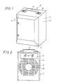
- the fan heater on which the exemplary embodiment is based is generally designated by l0. It has a housing 11 with an upper end wall 12. There, in the selected exemplary embodiment, a support bracket 15 is provided, which is fastened to the housing 11 with fastening elements, such as screws. With the help of such a bracket, the fan heater l0 is easy to transport and to be set up at the desired location in the room to be heated.
- the housing 11 also has side walls 13 of approximately rectangular shape. Connected to this and to the upper and lower end walls are front wall portions 14 which are beveled towards the front and which limit an opening 21 which is approximately rectangular in cross section, as can best be seen in FIG. 1.
- the rear wall of the housing 11 is designated 16. It has a control box 17 in its upper area, in which the switching and control devices can be accommodated.
- the front free ends of switches 18 protrude from the switch box 17, with which the switching and control devices accommodated in the switch box can be operated from the outside.
- Fig. 2 also shows that there are a plurality of openings 19 in the rear wall 16, which are designed slot-like and lie horizontally. Air can be drawn into the interior of the housing through the slots 19 when the fan is in operation.
- the rear wall 16 there is also a round opening 20 lying in the middle. This lies at the level of an electric motor 22, which has a known design and is therefore only shown schematically in FIG. 3.
- a fan 23 is driven, which sits on the drive shaft of the electric motor and also has a design known per se.
- a halogen lamp 24 is arranged as a heating device.
- a single halogen lamp 24 is present, which is designed as an elongated hollow cylinder body. It is a commercially available halogen lamp, which also applies to the associated sockets 27, which are fastened to diametrically opposite side walls of the housing 11 using a respective holding plate 28.
- Known connecting elements such as screws or the like, can be used to fasten the holding plates.
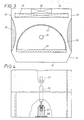
- the halogen lamp 24 is - as can best be seen in FIG. 3 of the drawing - surrounded by a reflector gate 25 which is semicircular in cross section and is made of a metallic material.
- the front free opening of the reflector 25 is covered by a glass ceramic plate 26. It can be a glass ceramic plate that is commercially available under the trademark "Ceran".
- the arrangement is such that the center of the halogen lamp lies at the focal point of the reflector 25, which is semicircular in cross section.
- the center of curvature of the reflector 25, which is semicircular in cross section, lies in the plane of the glass ceramic plate.
- the rays emanating from the halogen lamp 24 either go directly through the glass ceramic plate 26 and the opening 21 in the housing 11 into the room to be heated or they are first emitted in the direction of the inner wall of the reflector and thrown back from there and then reach the same way through the opening 21 of the housing 11 to the outside.
- the fan 23 driven by the electric motor 11 is generally used only in the heating phase, i.e. when the fan heater is installed in a cold room. If a certain temperature of the room is reached, the fan 23 can be switched off. This can be done either manually or automatically, for example using a thermal switch. If the fan 23 is in operation, air is drawn in through the slots 19 in the rear wall 16 of the housing 11. It is conveyed via air guide channels 30 in the direction of the opening of the housing 11. In order to achieve good air flow here, the air guide channels 30 are limited on the one hand by regions of the outer jacket of the reflector 25 and on the other hand by thickenings 29 which are provided on the inner walls of the housing 11.
- the heater housing had the dimensions 185 x 170 x 250 mm
- the ceramic plate had the dimensions 150 x 8 x 210 mm.
- the output of the halogen lamp was 750 watts.
- the temperature of the glass ceramic plate reached 250 ° C
- the temperature of the air near the fan heater reached 70 ° C.
- the air flow was 98.5 m3 / h
- the air speed was 0.76 m / sec.
- halogen lamp other than that shown could be accommodated in a housing. It would also be next to it possible to accommodate more than one halogen lamp in the interior of the reflector 25, or one could also mount several reflectors in one housing, one halogen lamp then being assigned to each reflector. This results in the possibility of carrying out a separate power supply to the individual halogen lamps via the control and switching directions, so that, for example, the entire halogen lamps housed in one housing burn together. In addition, individual or group operation of the halogen lamps is also possible.
- the housing of the fan heater has only a single outlet opening 21.
- the arrangement and design could also be such that a plurality of openings 21 are present in the housing 11, for example on diametrically opposite sides. This would of course have to be taken into account when arranging the halogen lamp and the associated reflector. In this case, radiation would take place in different directions. With such a design, it would be advisable to dimension the halogen lamp accordingly with regard to its power output.
Landscapes
- Engineering & Computer Science (AREA)
- Physics & Mathematics (AREA)
- Thermal Sciences (AREA)
- Chemical & Material Sciences (AREA)
- Combustion & Propulsion (AREA)
- Mechanical Engineering (AREA)
- General Engineering & Computer Science (AREA)
- Electric Stoves And Ranges (AREA)
- Direct Air Heating By Heater Or Combustion Gas (AREA)
Priority Applications (2)
| Application Number | Priority Date | Filing Date | Title |
|---|---|---|---|
| DE19853541423 DE3541423A1 (de) | 1985-11-23 | 1985-11-23 | Elektrisch betriebener heizluefter |
| EP87106552A EP0289635A1 (fr) | 1987-05-06 | 1987-05-06 | Appareil électrique de chauffage soufflant |
Applications Claiming Priority (1)
| Application Number | Priority Date | Filing Date | Title |
|---|---|---|---|
| EP87106552A EP0289635A1 (fr) | 1987-05-06 | 1987-05-06 | Appareil électrique de chauffage soufflant |
Publications (1)
| Publication Number | Publication Date |
|---|---|
| EP0289635A1 true EP0289635A1 (fr) | 1988-11-09 |
Family
ID=8196959
Family Applications (1)
| Application Number | Title | Priority Date | Filing Date |
|---|---|---|---|
| EP87106552A Withdrawn EP0289635A1 (fr) | 1985-11-23 | 1987-05-06 | Appareil électrique de chauffage soufflant |
Country Status (1)
| Country | Link |
|---|---|
| EP (1) | EP0289635A1 (fr) |
Cited By (3)
| Publication number | Priority date | Publication date | Assignee | Title |
|---|---|---|---|---|
| RU2156926C1 (ru) * | 2000-01-24 | 2000-09-27 | Бодров Виктор Георгиевич | Нагреватель воздуха |
| AT12731U1 (de) * | 2011-08-02 | 2012-10-15 | Abatec Products Gmbh | Infrarotstrahler |
| CN115682103A (zh) * | 2021-07-28 | 2023-02-03 | 美的集团武汉制冷设备有限公司 | 辐射模块、空调室内机以及空调器 |
Citations (4)
| Publication number | Priority date | Publication date | Assignee | Title |
|---|---|---|---|---|
| CH341923A (de) * | 1954-10-28 | 1959-10-31 | Siemens Ag | Elektrischer Raumheizofen mit Lüfter für die Erzeugung eines an einem Heizkörper vorbeistreichenden Luftstromes |
| US3240915A (en) * | 1962-09-19 | 1966-03-15 | Fostoria Corp | Infra-red heater |
| US3278722A (en) * | 1961-12-29 | 1966-10-11 | Hupp Corp | Electric infra-red radiant space heater unit |
| DE3541423A1 (de) * | 1985-11-23 | 1987-05-27 | Krups Stiftung | Elektrisch betriebener heizluefter |
-
1987
- 1987-05-06 EP EP87106552A patent/EP0289635A1/fr not_active Withdrawn
Patent Citations (4)
| Publication number | Priority date | Publication date | Assignee | Title |
|---|---|---|---|---|
| CH341923A (de) * | 1954-10-28 | 1959-10-31 | Siemens Ag | Elektrischer Raumheizofen mit Lüfter für die Erzeugung eines an einem Heizkörper vorbeistreichenden Luftstromes |
| US3278722A (en) * | 1961-12-29 | 1966-10-11 | Hupp Corp | Electric infra-red radiant space heater unit |
| US3240915A (en) * | 1962-09-19 | 1966-03-15 | Fostoria Corp | Infra-red heater |
| DE3541423A1 (de) * | 1985-11-23 | 1987-05-27 | Krups Stiftung | Elektrisch betriebener heizluefter |
Cited By (3)
| Publication number | Priority date | Publication date | Assignee | Title |
|---|---|---|---|---|
| RU2156926C1 (ru) * | 2000-01-24 | 2000-09-27 | Бодров Виктор Георгиевич | Нагреватель воздуха |
| AT12731U1 (de) * | 2011-08-02 | 2012-10-15 | Abatec Products Gmbh | Infrarotstrahler |
| CN115682103A (zh) * | 2021-07-28 | 2023-02-03 | 美的集团武汉制冷设备有限公司 | 辐射模块、空调室内机以及空调器 |
Similar Documents
| Publication | Publication Date | Title |
|---|---|---|
| EP0236851B1 (fr) | Couveuse pour bébé | |
| DE1540782C3 (de) | Elektrisches Raumheizgerat mit Zwangsluftumlauf | |
| CH642829A5 (de) | Haartrockner mit einer infrarotwaermequelle. | |
| DE3104677A1 (de) | Backofen, vorzugsweise mit einer thermischen heizeinrichtung sowie mit einer mikrowellen-heizeinrichtung | |
| DE69929556T2 (de) | Kühlvorrichtung für Halogenlampen in Mikrowellenöfen | |
| DE4015639C2 (fr) | ||
| EP0289635A1 (fr) | Appareil électrique de chauffage soufflant | |
| CH642506A5 (de) | Mikrowellenofen. | |
| DE3317714A1 (de) | Trockenvorrichtung fuer eine sich bewegende materialbahn | |
| CH637794A5 (en) | Microwave oven | |
| DE3541423A1 (de) | Elektrisch betriebener heizluefter | |
| WO2001071868A1 (fr) | Armoire de commande et ensemble pour armoire de commande | |
| DE2615604B2 (de) | Backofen, insbesondere mit Mitteln zur pyrolytischen Reinigung mit einem Kühlluftgebläse | |
| DE3442848A1 (de) | Backofen | |
| DE8120029U1 (de) | Infrarot-bestrahlungsgeraet fuer wellenlaengen von ungefaehr 800 bis 1200 nm | |
| DE202018006669U1 (de) | Vorrichtung zur thermischen Wildkrautbeseitigung | |
| EP0003764A1 (fr) | Four de cuisson double, en particulier four de cuisson encastré | |
| DE3412848C2 (de) | Handhabungsgerät | |
| EP0142621A1 (fr) | Machine à coudre les fourrures | |
| DE3404282A1 (de) | Hochleistungs-foengeraet | |
| DE20302352U1 (de) | Vorrichtung zum Erwärmen von Geschirrteilen | |
| DE3147044C2 (fr) | ||
| DE3049922C2 (de) | Mikrowellen-kochherd | |
| DE2836118C2 (de) | Backofen | |
| DE3703125A1 (de) | Konvektionsheizung |
Legal Events
| Date | Code | Title | Description |
|---|---|---|---|
| PUAI | Public reference made under article 153(3) epc to a published international application that has entered the european phase |
Free format text: ORIGINAL CODE: 0009012 |
|
| AK | Designated contracting states |
Kind code of ref document: A1 Designated state(s): AT BE FR GB IT NL |
|
| 17P | Request for examination filed |
Effective date: 19881019 |
|
| 17Q | First examination report despatched |
Effective date: 19890118 |
|
| STAA | Information on the status of an ep patent application or granted ep patent |
Free format text: STATUS: THE APPLICATION HAS BEEN WITHDRAWN |
|
| 18W | Application withdrawn |
Withdrawal date: 19891205 |
|
| R18W | Application withdrawn (corrected) |
Effective date: 19891205 |
|
| RIN1 | Information on inventor provided before grant (corrected) |
Inventor name: HOFFMANN, ERICH |