EP0289645A1 - Infrarotsignalsystem zum Erfassen eines vorbestimmten Zustandes eines Hochspannungsgeräts - Google Patents
Infrarotsignalsystem zum Erfassen eines vorbestimmten Zustandes eines Hochspannungsgeräts Download PDFInfo
- Publication number
- EP0289645A1 EP0289645A1 EP87111186A EP87111186A EP0289645A1 EP 0289645 A1 EP0289645 A1 EP 0289645A1 EP 87111186 A EP87111186 A EP 87111186A EP 87111186 A EP87111186 A EP 87111186A EP 0289645 A1 EP0289645 A1 EP 0289645A1
- Authority
- EP
- European Patent Office
- Prior art keywords
- housing
- semaphore
- reflecting surface
- predetermined condition
- arm
- Prior art date
- Legal status (The legal status is an assumption and is not a legal conclusion. Google has not performed a legal analysis and makes no representation as to the accuracy of the status listed.)
- Withdrawn
Links
- 230000011664 signaling Effects 0.000 title claims abstract description 11
- 238000001514 detection method Methods 0.000 claims abstract description 18
- 238000000034 method Methods 0.000 claims description 6
- 230000008859 change Effects 0.000 claims description 3
- 238000006073 displacement reaction Methods 0.000 claims description 2
- 230000000149 penetrating effect Effects 0.000 claims 1
- 230000001681 protective effect Effects 0.000 claims 1
- 230000004308 accommodation Effects 0.000 abstract 1
- 230000007246 mechanism Effects 0.000 description 3
- 239000000470 constituent Substances 0.000 description 2
- 239000012212 insulator Substances 0.000 description 2
- 230000000007 visual effect Effects 0.000 description 2
- 240000008042 Zea mays Species 0.000 description 1
- 230000035508 accumulation Effects 0.000 description 1
- 238000009825 accumulation Methods 0.000 description 1
- 230000009471 action Effects 0.000 description 1
- 230000004913 activation Effects 0.000 description 1
- 230000008901 benefit Effects 0.000 description 1
- 230000005540 biological transmission Effects 0.000 description 1
- 230000008878 coupling Effects 0.000 description 1
- 238000010168 coupling process Methods 0.000 description 1
- 238000005859 coupling reaction Methods 0.000 description 1
- 239000007788 liquid Substances 0.000 description 1
- 239000002184 metal Substances 0.000 description 1
- 238000009738 saturating Methods 0.000 description 1
Images
Classifications
-
- H—ELECTRICITY
- H01—ELECTRIC ELEMENTS
- H01H—ELECTRIC SWITCHES; RELAYS; SELECTORS; EMERGENCY PROTECTIVE DEVICES
- H01H9/00—Details of switching devices, not covered by groups H01H1/00 - H01H7/00
- H01H9/16—Indicators for switching condition, e.g. "on" or "off"
- H01H9/168—Indicators for switching condition, e.g. "on" or "off" making use of an electromagnetic wave communication
-
- H—ELECTRICITY
- H01—ELECTRIC ELEMENTS
- H01H—ELECTRIC SWITCHES; RELAYS; SELECTORS; EMERGENCY PROTECTIVE DEVICES
- H01H31/00—Air-break switches for high tension without arc-extinguishing or arc-preventing means
- H01H31/26—Air-break switches for high tension without arc-extinguishing or arc-preventing means with movable contact that remains electrically connected to one line in open position of switch
- H01H31/28—Air-break switches for high tension without arc-extinguishing or arc-preventing means with movable contact that remains electrically connected to one line in open position of switch with angularly-movable contact
Definitions
- the present invention relates to a semaphore for use in a detection system as well as a method for detecting a predetermined condition in a high voltage (HV) device, and according to which when the predetermined condition of the device is detected, it results therefrom.
- HV high voltage
- a signaling system is described associated with a high voltage device hereinafter called a disconnector device, intended to detect the relative position of a movable contact relative to a fixed contact.
- the system as described in this patent is of the ultrasonic type. It is extremely expensive to build and is not effective when the climate is severe, especially during a snowstorm, when the reflecting surface of the mirrors in the receiving device can be obstructed by snow and ice, thus making the receiver imprecise.
- the infrared signaling system according to the present invention has been designed for use with a high voltage disconnector of the type described in the patent referred to above, which is provided with a fixed contact and with a movable contact, and such than used in an electrical distribution and transport network.
- the detection system can have other applications with other high voltage devices, in particular for signaling a gas pressure or liquid level threshold in a very high voltage device.
- One aspect of the present invention is a detection system using a semaphore to signal a predetermined condition of a high voltage device by reflecting infrared signals continuously generated towards the retroreflector of the semaphore, the signals then being returned by the retroreflector. pivotally mounted in the semaphore housing.
- Another aspect of the present invention resides in a method of detecting a predetermined condition of a high-voltage device using an infrared detection system consisting of a semaphore comprising a retroreflective element pivotally mounted to reflect the infrared signals generated continuously towards the retroreflector of the semaphore, upon detection of a predetermined condition of the device high tension.
- the present invention relates to a semaphore for use in a detection system for a high voltage device (HT) and for signaling a predetermined condition of the device.
- the semaphore includes a housing inside which a retroreflective element is supported.
- the housing has a port and the retroreflector has a reflective surface which is supported to align with the port.
- Means are provided for mounting the housing near the device.
- a link is connected to the housing as well as to the device and is activated when a predetermined condition occurs placing the reflecting surface inside the housing in a position to reflect signals through the orifice.
- a remote sensing device continuously generates infrared signals towards the retroreflector, and detects signals reflected by the reflecting surface of the retroreflector.
- the present invention constitutes a method for detecting a predetermined condition of a high voltage (HV) device.
- the method is characterized in that a retroreflective device is supported in a housing provided with an orifice aligned with the retroreflective device.
- the retroreflective device has a reflecting surface and is pivoted so as to adopt a reflecting position and non-reflective.
- a predetermined condition of a high voltage device is perceived through a connecting means mounted to rotate the retroreflective device.
- Infrared signals are transmitted to the retroreflector, and a detector detects infrared signals that are returned by the reflective surface of the retroreflector when the latter is placed in the reflective position by the link, while the predetermined condition of the HT device occurs.
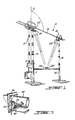
- a high voltage disconnector which is usually connected to a transmission line of a three-phase electric transport network (not illustrated).
- the disconnector essentially consists of two metal support structures 11 and 12, each having a procelain insulator column 13 and 15, respectively.
- An additional column of insulators 15 is connected with the contact displacement arm 16 of the disconnector and can be rotated by the motorized drive mechanism 17 so as to cause the axial rotation of the contact blade 16.
- a structure of this kind is well known in the art.
- the fixed contact comprises pairs of contact fingers mounted one opposite the other, in particular the fingers 19 and 20, the contact finger 19 being carried towards the fixed finger 20 by means of a spring.
- the drive 17 makes it undergo an axial rotation so as to assume the position illustrated in FIG. 2, the contact jaw then being open and a pressure exerted on the blade by the contact fingers 19 and 20. This ensures good electrical conduction through the fixed contact.
- a cable 21 is provided with an internal movable wire 22 connected to the movable contact finger 19 so as to transmit a mechanical signal translating the position of the movable finger when this the latter is engaged by the blade, as can be seen in FIG. 2.
- the internal wire 22 may also be called upon to move by using forged fingers specially shaped, and mounted close to normal fingers.
- the detection and signaling system consists of a semaphore 25 and 25 ⁇ respectively connected to the movable contact 16 and the fixed contact 18.
- the set of two devices infrared detection 26 and 26 ⁇ is associated with its respective semaphore 25 and 25 ⁇ , and generates and detects a narrow beam of infrared signals at their respective semaphores, more precisely at the orifice 33 thereof.
- These detectors 26 are well known in the art and are supplied by Banner, Model SBLX-1, which is a detector for retroreflector for very precise purposes for long range applications.
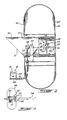
- the semaphore consists of a sub-assembly comprising a housing 27, containing a retroreflective element 28.
- a second sub-assembly comprising a housing 29 consists of 'a rounded wall so as to protect against the discharge of emanations emitted by the surrounding high-voltage circuits, and prevent direct sunlight from saturating the receiver incorporated in the detection device 26.
- the front face 30 of the housing 29 is preferably made of a non-reflective finish.
- a tubing 31 is also an inherent part of the sub-assembly 27 and constitutes a housing for the retroreflector 28.
- the tubing also defines the orifice 33 which receives the infrared signals and reflects them when the retroreflector 28 is in the reflecting position. as illustrated in Figure 2.
- a screen 32 is formed by an extension of the tubing 31 which projects beyond the front face 30 in order to prevent accumulations of snow pushed by the wind on the retroreflector.
- the retroreflector is a tetrahedral type reflector having a reflective surface 34 and disposed on a pivot connection, fixed to the disc 35 located outside the tubing 32 (see Figure 3).
- the retroreflective disc 28 can move from a non-reflective position, illustrated in dotted lines by the reference numeral 28 ⁇ , to a reflective position as illustrated in Figure 2. This movement is effected by means of a rocker link comprising a pivoting arm 36 having an intermediate pivot 37.
- the wire 22 from the movable contact finger 19 is fixed to one end of the pivoting arm 36 by means of a suitable clip 38.
- the other end of the arm is provided with a flexible connection element constituted by a spring connection 39, the spring having one end 40 connected to the arm 36 and the other end 41 connected to the disc 35.
- the pivoting arm 36 is normally biased downwards by a tension spring 42, while the disc takes the non-reflecting position illustrated in 28 ⁇ .
- the infrared signals generated by the detector consisted of pulsed infrared signals, and these had the advantage of preventing the detector from being affected by ambient infrared rays which could be indirectly emitted by the sun or any other light source, including electric arcs.
- the link should include a pressure gauge 50, a connection 51 of which disengages from a connection 52 associated with the retro-reflector 53.
- the connectors 51 and 52 would disengage 35 would cause the retroreflector 53 to take a horizontal position resulting from the action of a spring biasing means, not illustrated, in order to prevent the reflection of the infrared rays 54 which are directed towards the orifice 55 of housing 56.
- the present invention provides a method and system for detecting a predetermined condition in a high voltage (HV) device via a retroreflective device supported in a housing.
- the housing is provided with a hole aligned with the retroreflector.
- the retroreflective device has a reflecting surface which is pivotally mounted to move between a reflecting position and a non-reflecting position.
- a predetermined condition of the HT device is perceived by a link which is connected with the retroreflective device so as to rotate the latter, so that upon detection of the predetermined condition, the retroreflective surface is placed so as to return the infrared signals which are continuously transmitted towards the opening to the retroreflector by means of a detection device located at a distance from the semaphore.
Landscapes
- Physics & Mathematics (AREA)
- Electromagnetism (AREA)
- Photometry And Measurement Of Optical Pulse Characteristics (AREA)
- Switches Operated By Changes In Physical Conditions (AREA)
- Testing Electric Properties And Detecting Electric Faults (AREA)
- Protection Of Static Devices (AREA)
Applications Claiming Priority (2)
| Application Number | Priority Date | Filing Date | Title |
|---|---|---|---|
| CA000534870A CA1262268A (fr) | 1987-04-16 | 1987-04-16 | Systeme de signalisation a l'infrarouge pour detecter une condition predeteriminee d'un dispositif a haute tension |
| CA534870 | 1987-04-16 |
Publications (1)
| Publication Number | Publication Date |
|---|---|
| EP0289645A1 true EP0289645A1 (de) | 1988-11-09 |
Family
ID=4135446
Family Applications (1)
| Application Number | Title | Priority Date | Filing Date |
|---|---|---|---|
| EP87111186A Withdrawn EP0289645A1 (de) | 1987-04-16 | 1987-08-03 | Infrarotsignalsystem zum Erfassen eines vorbestimmten Zustandes eines Hochspannungsgeräts |
Country Status (4)
| Country | Link |
|---|---|
| US (1) | US4806925A (de) |
| EP (1) | EP0289645A1 (de) |
| JP (1) | JPS63263477A (de) |
| CA (1) | CA1262268A (de) |
Cited By (1)
| Publication number | Priority date | Publication date | Assignee | Title |
|---|---|---|---|---|
| EP1788599A1 (de) * | 2005-11-22 | 2007-05-23 | Schneider Electric Industries Sas | Vorrichtung und Überwachungsverfahren für elektrische Einrichtungen |
Families Citing this family (2)
| Publication number | Priority date | Publication date | Assignee | Title |
|---|---|---|---|---|
| US5200851A (en) * | 1992-02-13 | 1993-04-06 | Minnesota Mining And Manufacturing Company | Infrared reflecting cube-cornered sheeting |
| US7626287B2 (en) * | 2005-04-06 | 2009-12-01 | Dean Sanders | High voltage loadbreak switch safety indicator |
Citations (4)
| Publication number | Priority date | Publication date | Assignee | Title |
|---|---|---|---|---|
| FR1010779A (fr) * | 1948-10-23 | 1952-06-16 | Electricite De France | Perfectionnements apportés aux moyens pour assurer la commande et la surveillance d'appareils électriques à haute tension, tels que disjoncteurs, sectionneurs, etc. |
| FR2036481A5 (de) * | 1968-09-02 | 1970-12-24 | Transformatorenwerk | |
| EP0088155A2 (de) * | 1981-12-24 | 1983-09-14 | Hydro-Quebec | Ultraschall-Positionsmelder für Trennschalter |
| US4570062A (en) * | 1982-05-01 | 1986-02-11 | Hitachi Kidenkogyo Kabushiki Kaisha | System for optically transferring information between a moving object and a fixed position |
Family Cites Families (5)
| Publication number | Priority date | Publication date | Assignee | Title |
|---|---|---|---|---|
| US3852556A (en) * | 1969-12-31 | 1974-12-03 | Westinghouse Electric Corp | Combination hand-jack, semaphore and travel indicator for high-voltage circuit interrupter |
| US3659949A (en) * | 1970-04-20 | 1972-05-02 | Technidyne Inc | Laser beam systems and apparatus for detecting and measuring parametric deviations between surfaces and the like |
| DE2711416C2 (de) * | 1977-03-16 | 1982-12-09 | Werner Turck Gmbh & Co Kg, 5884 Halver | Anordnung zur Anzeige des Schaltungszustandes der Schalter |
| DE7815175U1 (de) * | 1978-05-19 | 1978-10-12 | Erwin Sick Gmbh Optik-Elektronik, 7808 Waldkirch | Lichtschrankenempfaenger |
| DE3237035C1 (de) * | 1982-10-06 | 1984-01-26 | Erwin Sick Gmbh Optik-Elektronik, 7808 Waldkirch | Reflexionslichtschranke |
-
1987
- 1987-04-16 CA CA000534870A patent/CA1262268A/fr not_active Expired
- 1987-04-24 US US07/042,441 patent/US4806925A/en not_active Expired - Fee Related
- 1987-07-29 JP JP62189968A patent/JPS63263477A/ja active Pending
- 1987-08-03 EP EP87111186A patent/EP0289645A1/de not_active Withdrawn
Patent Citations (4)
| Publication number | Priority date | Publication date | Assignee | Title |
|---|---|---|---|---|
| FR1010779A (fr) * | 1948-10-23 | 1952-06-16 | Electricite De France | Perfectionnements apportés aux moyens pour assurer la commande et la surveillance d'appareils électriques à haute tension, tels que disjoncteurs, sectionneurs, etc. |
| FR2036481A5 (de) * | 1968-09-02 | 1970-12-24 | Transformatorenwerk | |
| EP0088155A2 (de) * | 1981-12-24 | 1983-09-14 | Hydro-Quebec | Ultraschall-Positionsmelder für Trennschalter |
| US4570062A (en) * | 1982-05-01 | 1986-02-11 | Hitachi Kidenkogyo Kabushiki Kaisha | System for optically transferring information between a moving object and a fixed position |
Non-Patent Citations (1)
| Title |
|---|
| ELEKTOR, vol. 9, no. 11, novembre 1983, pages 1158-1160, Canterbury, Kent, GB; L. VAN BOVEN: "Ultrasonic/infrared barrier" * |
Cited By (3)
| Publication number | Priority date | Publication date | Assignee | Title |
|---|---|---|---|---|
| EP1788599A1 (de) * | 2005-11-22 | 2007-05-23 | Schneider Electric Industries Sas | Vorrichtung und Überwachungsverfahren für elektrische Einrichtungen |
| FR2893742A1 (fr) * | 2005-11-22 | 2007-05-25 | Schneider Electric Ind Sas | Dispositif et procede de surveillance pour appareillage c electrique |
| CN1971648B (zh) * | 2005-11-22 | 2010-08-18 | 施耐德电器工业公司 | 用于监控电设备的方法和设备 |
Also Published As
| Publication number | Publication date |
|---|---|
| CA1262268A (fr) | 1989-10-10 |
| JPS63263477A (ja) | 1988-10-31 |
| US4806925A (en) | 1989-02-21 |
Similar Documents
| Publication | Publication Date | Title |
|---|---|---|
| EP0046096A1 (de) | Einrichtung zur Bestimmung der Lage und der Verriegelung einer Schubumkehrvorrichtung eines Turboreaktors | |
| EP1542253B1 (de) | Anzeigeeinrichtung einer Auslöseeinrichtung eines elektrischen Schutzgeräts | |
| EP3499541B1 (de) | Elektrisches schutzgerät, das ein pyrotechnisches betätigungssystem umfasst | |
| CA2238903A1 (fr) | Methode de controle et diagnostic du fonctionnement d'un appareillage electrique a haute tension | |
| EP0540398B1 (de) | Verbindungsbaugruppe vom Typ Schaltungsschleife | |
| EP0289645A1 (de) | Infrarotsignalsystem zum Erfassen eines vorbestimmten Zustandes eines Hochspannungsgeräts | |
| EP2717284B1 (de) | Bedienungsvorrichtung eines elektrischen Schutzschaltgeräts, und diese umfassendes elektrisches Schutzschaltgerät | |
| EP0773573B1 (de) | Sicherungseinsatz mit Ansprechanzeiger | |
| EP0088155B1 (de) | Ultraschall-Positionsmelder für Trennschalter | |
| CH666766A5 (fr) | Disjoncteur a contact escamotable telecommande en un point centre sur l'axe de deplacement de l'electro-aimant de telecommande. | |
| FR2746957A1 (fr) | Mecanisme de commande d'un disjoncteur a grand angle d'ouverture | |
| WO2008031838A1 (fr) | Systeme anti-intrusion pour la protection de composants electroniques | |
| WO2011135034A1 (fr) | Sectionneur de terre a encombrement reduit | |
| EP3868988B1 (de) | Verbesserte verriegelungsvorrichtung | |
| FR2801875A1 (fr) | Dispositif de securite d'une porte d'ascenseur | |
| EP1544884B1 (de) | Beweglicher Schutzschalter mit Rückstellberechtigungsmechanismus. | |
| EP0926694B1 (de) | Magnetothermische Steuervorrichtung und mit einer solchen Vorrichtung ausgerüsteter Schutzschalter | |
| EP0390618B1 (de) | Hindernisdetektor | |
| EP4453986B1 (de) | Elektrisches schaltgerät mit hilfskontakt | |
| EP2642502B1 (de) | Auslöseblock für elektrisches Sicherungsgerät, und mit einem solchen Block ausgestattetes elektrisches Sicherungsgerät | |
| EP0936120B1 (de) | Betätigungsvorrichtung für eine gelenkige Einstiegsstufe für ein Fahrzeug und Einstiegsvorrichtung für ein Fahrzeug, insbesondere Eisenbahnfahrzeug, mit einer solchen Betätigungsvorrichtung | |
| FR2954851A1 (fr) | Dispositif securise de controle de position d'appareil haute tension | |
| FR2694444A1 (fr) | Perfectionnements aux dispositifs de coupure de ligne électrique. | |
| EP0881654B1 (de) | Elektrische Sicherung | |
| EP1749305A1 (de) | Steuervorrichtung für ein elektrisches gerät |
Legal Events
| Date | Code | Title | Description |
|---|---|---|---|
| PUAI | Public reference made under article 153(3) epc to a published international application that has entered the european phase |
Free format text: ORIGINAL CODE: 0009012 |
|
| AK | Designated contracting states |
Kind code of ref document: A1 Designated state(s): AT BE CH DE ES FR GB GR IT LI LU NL SE |
|
| 17P | Request for examination filed |
Effective date: 19881221 |
|
| 17Q | First examination report despatched |
Effective date: 19910918 |
|
| STAA | Information on the status of an ep patent application or granted ep patent |
Free format text: STATUS: THE APPLICATION IS DEEMED TO BE WITHDRAWN |
|
| 18D | Application deemed to be withdrawn |
Effective date: 19920129 |
|
| RIN1 | Information on inventor provided before grant (corrected) |
Inventor name: BELANGER, YVES Inventor name: SIMARD, JULIEN Inventor name: LESSARD, RAYMOND |