EP0289675A1 - Procédé et disposition de soupape pour améliorer le mélange air-carburant - Google Patents
Procédé et disposition de soupape pour améliorer le mélange air-carburant Download PDFInfo
- Publication number
- EP0289675A1 EP0289675A1 EP87304131A EP87304131A EP0289675A1 EP 0289675 A1 EP0289675 A1 EP 0289675A1 EP 87304131 A EP87304131 A EP 87304131A EP 87304131 A EP87304131 A EP 87304131A EP 0289675 A1 EP0289675 A1 EP 0289675A1
- Authority
- EP
- European Patent Office
- Prior art keywords
- valve
- air
- fuel
- cylinder
- seat
- Prior art date
- Legal status (The legal status is an assumption and is not a legal conclusion. Google has not performed a legal analysis and makes no representation as to the accuracy of the status listed.)
- Granted
Links
Images
Classifications
-
- F—MECHANICAL ENGINEERING; LIGHTING; HEATING; WEAPONS; BLASTING
- F01—MACHINES OR ENGINES IN GENERAL; ENGINE PLANTS IN GENERAL; STEAM ENGINES
- F01L—CYCLICALLY OPERATING VALVES FOR MACHINES OR ENGINES
- F01L3/00—Lift-valve, i.e. cut-off apparatus with closure members having at least a component of their opening and closing motion perpendicular to the closing faces; Parts or accessories thereof
- F01L3/22—Valve-seats not provided for in preceding subgroups of this group; Fixing of valve-seats
-
- F—MECHANICAL ENGINEERING; LIGHTING; HEATING; WEAPONS; BLASTING
- F02—COMBUSTION ENGINES; HOT-GAS OR COMBUSTION-PRODUCT ENGINE PLANTS
- F02B—INTERNAL-COMBUSTION PISTON ENGINES; COMBUSTION ENGINES IN GENERAL
- F02B31/00—Modifying induction systems for imparting a rotation to the charge in the cylinder
-
- Y—GENERAL TAGGING OF NEW TECHNOLOGICAL DEVELOPMENTS; GENERAL TAGGING OF CROSS-SECTIONAL TECHNOLOGIES SPANNING OVER SEVERAL SECTIONS OF THE IPC; TECHNICAL SUBJECTS COVERED BY FORMER USPC CROSS-REFERENCE ART COLLECTIONS [XRACs] AND DIGESTS
- Y02—TECHNOLOGIES OR APPLICATIONS FOR MITIGATION OR ADAPTATION AGAINST CLIMATE CHANGE
- Y02T—CLIMATE CHANGE MITIGATION TECHNOLOGIES RELATED TO TRANSPORTATION
- Y02T10/00—Road transport of goods or passengers
- Y02T10/10—Internal combustion engine [ICE] based vehicles
- Y02T10/12—Improving ICE efficiencies
Definitions
- This invention pertains to a novel method, and a valving arrangement for improving fuel/air mixing when gaseous fuel is directly injected either into a cylinder or into the cylinder's air intake passage during the intake process, and in particular, to such a method and valving arrangement which provides for a high-velocity air injection into the cylinder to improve air-fuel admixing swirl.
- the gaseous fuel is generally injected directly into the cylinder during the intake stroke.
- the mixing of the fuel and air streams depends on the flow pattern and turbulence which, in turn, are affected by the intake passage configuration, and the valve size and location relative to the fuel injection point.
- Experience shows us that the mixing is generally poor, and that the mixture at the end of the compression stroke is far from homogeneous.
- limited improvements can be made by optimizing the air intake passage direction to generate swirl, the results are not good enough, from the standpoint of minimizing exhaust emission, and cycle-to-cycle variations in firing pressure. An improved method and a valving arrangement for improving the mixing has been needed.
- the method for improving the air-fuel mixing in a gas engine is to inject the fuel into the air intake passage so that partial mixing is established prior to entry of the air and fuel through the value.
- the high-velocity of the air and fuel through the value, and the turbulence generated thereby, will cause further improved mixing in the cylinder.
- the air intake value for the cylinder closes down following the normal curve; i.e., as a fuel gas in injected, and the piston approaches bottom dead center.
- the value closes to about ten to two percent of its full displacement, it is teaching of this invention to keep the value at this limited opening until the piston completes the remainder of the downstroke. Due to expansion of the air in the cylinder, the pressure differential increases during this period when the value is merely cracked open, and therefore the velocity of the air jet entering the cylinder increases significantly.
- the momentum of the air jet is high enough to improve the flow field in the cylinder.
- the valve must be fully closed.
- the novel method also comprehends injecting a high-velocity air steam into the cylinder through only one side of the air intake valve just before the piston reaches bottom dead center.
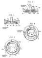
- an air intake valve 10 for a cylinder closes upon, and removes from, a valve seat 12, to control flow of fluid (i.e., air or air and fuel) therethrough from the inlet 14 to the outlet 16.
- fluid i.e., air or air and fuel
- the seat 12 has a land 18 which is concentric with a sealing surface 20 formed on the valve 10. Consequently, as is conventional, when the surface 20 closes upon the land 18, no fluid can flow between the inlet 14 and outlet 16.
- our valving arrangement comprises means for effecting an early closure of one side of the valve 10 before the closure of the other side.
- Seat 12 has a recess 22 formed of two radii.
- a first radius 24 forms the half 22a of the recess 22 which is at the left (in Figures 1 and 2), and a second radius 26 forms the half 22b of the recess 22 which is at the right.
- the valve 10 has an outermost shoulder 28 which effects a substantial closure of the valve at the left-hand side thereof, as the shoulder 28 and half 22a matingly substantially close upon each other; radius 24 closely approximates the radius of recess half 22a. Between recess half 22b and shoulder 28, however, these obtains a crescent-shaped space 20 which communicates with the annular void between land 18 and surface 20. It is through this space 30 that fluid enters the cylinder (not shown) at a high velocity to enhance a swirl in the cylinder, just prior to full valve closure.
- FIGS 3 and 4 depict an alternative valving arrangement in accordance with the invention.
- similar or same index numbers denote similar or same components or structures as are presented in Figures 1 and 2.
- a valve 10a has a seat 12a defining the inlet 14 and outlet 16. In this embodiment, early closure of one side (i.e., the left side) of the valve 10a occurs at the inlet 14, whereas in the Figures 1 and 2 embodiment it occurred at the outlet 16.
- the seat 12a has a surface 32 defined by two radii 24a and 26a.
- the former is a mating complement to a smaller-diameter should 28a formed on the valve 10a, whereas the latter defines another crescent-shaped space 30a with shoulder 28a.
Landscapes
- Engineering & Computer Science (AREA)
- Mechanical Engineering (AREA)
- General Engineering & Computer Science (AREA)
- Chemical & Material Sciences (AREA)
- Combustion & Propulsion (AREA)
- Fuel-Injection Apparatus (AREA)
Priority Applications (1)
| Application Number | Priority Date | Filing Date | Title |
|---|---|---|---|
| DE8787304131T DE3775390D1 (de) | 1986-05-05 | 1987-05-08 | Verfahren und vorrichtung bei ventilen zur verbesserung der luft-kraftstoff-mischung. |
Applications Claiming Priority (1)
| Application Number | Priority Date | Filing Date | Title |
|---|---|---|---|
| US85936686A | 1986-05-05 | 1986-05-05 |
Publications (2)
| Publication Number | Publication Date |
|---|---|
| EP0289675A1 true EP0289675A1 (fr) | 1988-11-09 |
| EP0289675B1 EP0289675B1 (fr) | 1991-12-18 |
Family
ID=25330750
Family Applications (1)
| Application Number | Title | Priority Date | Filing Date |
|---|---|---|---|
| EP87304131A Expired - Lifetime EP0289675B1 (fr) | 1986-05-05 | 1987-05-08 | Procédé et disposition de soupape pour améliorer le mélange air-carburant |
Country Status (4)
| Country | Link |
|---|---|
| US (1) | US4756281A (fr) |
| EP (1) | EP0289675B1 (fr) |
| DE (1) | DE3775390D1 (fr) |
| YU (1) | YU78487A (fr) |
Families Citing this family (14)
| Publication number | Priority date | Publication date | Assignee | Title |
|---|---|---|---|---|
| US5230310A (en) * | 1991-03-29 | 1993-07-27 | Mazda Motor Corporation | Combustion chamber of internal combustion engine |
| JP3394363B2 (ja) * | 1995-06-28 | 2003-04-07 | ヤマハ発動機株式会社 | エンジン用シリンダヘッド |
| US5558061A (en) * | 1995-12-22 | 1996-09-24 | General Motors Corporation | Engine cylinder intake port |
| US5601061A (en) * | 1996-05-16 | 1997-02-11 | Caterpillar Inc. | Engine intake air deflector |
| US5709183A (en) * | 1996-12-23 | 1998-01-20 | Chrysler Corporation | Shroud and combustion chamber for an internal combustion engine |
| US6089203A (en) * | 1998-12-23 | 2000-07-18 | Ford Global Technologies, Inc. | Internal combustion engine with offset intake valve seat for improved intake charge motion |
| SE521981C2 (sv) | 1999-06-11 | 2003-12-23 | Volvo Personvagnar Ab | Metod för att minska ämnen i avgaser från en förbränningsmotor |
| US6260530B1 (en) * | 1999-11-17 | 2001-07-17 | Joseph J. Keon, Jr. | Vortex-inducing valve seat insert |
| US6877525B2 (en) | 2001-11-07 | 2005-04-12 | Delphi Technologies, Inc. | Check valve for fuel pump |
| US6971405B2 (en) * | 2002-10-09 | 2005-12-06 | Delphi Technologies, Inc. | Check valve for fuel pump |
| US6994108B2 (en) * | 2003-03-04 | 2006-02-07 | Delphi Technologies, Inc. | Check valve for fuel pump |
| DE102007018917A1 (de) * | 2007-04-19 | 2008-10-23 | Mahle International Gmbh | Brennkraftmaschine |
| EP2698508A1 (fr) * | 2012-08-17 | 2014-02-19 | MWM GmbH | Tête de vérin avec fraisure |
| JP6360505B2 (ja) * | 2016-01-06 | 2018-07-18 | 本田技研工業株式会社 | 内燃機関 |
Citations (8)
| Publication number | Priority date | Publication date | Assignee | Title |
|---|---|---|---|---|
| FR685210A (fr) * | 1928-11-20 | 1930-07-08 | Fusion Moteurs | Perfectionnements apportés aux moteurs à explosions à quatre temps et à carburant liquide, notamment aux moteurs dits du type fixe |
| US3046960A (en) * | 1960-09-26 | 1962-07-31 | Fiat Motor Company | Internal combustion engines |
| US4064849A (en) * | 1974-01-17 | 1977-12-27 | Nissan Motor Co., Ltd. | Internal combustion engine |
| DE2749730A1 (de) * | 1976-11-08 | 1978-05-18 | Nissan Motor | Viertakt-kolben-verbrennungsmotor und verfahren zu dessen betrieb |
| US4133322A (en) * | 1976-04-02 | 1979-01-09 | Mitsubishi Jidosha Kogyo Kabushiki Kaisha | Internal combustion engine |
| EP0045669A1 (fr) * | 1980-06-04 | 1982-02-10 | Georges Durand | Procédé de fonctionnement d'un moteur à combustion interne à expansion prolongée avec suralimentation relative |
| DE3141663A1 (de) * | 1981-10-21 | 1983-05-05 | Bayerische Motoren Werke AG, 8000 München | Gemischverdichtende, fremdgezuendete brennkraftmaschine |
| DE3515043A1 (de) * | 1984-04-27 | 1985-11-07 | Mazda Motor Corp., Hiroshima | Brennkraftmaschine mit brennstoff-einspritzung |
Family Cites Families (6)
| Publication number | Priority date | Publication date | Assignee | Title |
|---|---|---|---|---|
| FR527918A (fr) * | 1920-12-04 | 1921-11-03 | Simon Mery | Came distributrice silencieuse pour moteurs à explosion |
| US2593769A (en) * | 1945-12-11 | 1952-04-22 | Kollsman Paul | Engine fuel injection |
| US2647500A (en) * | 1950-10-28 | 1953-08-04 | Lang Heinrich | Valve gear for diesel engines |
| US3146764A (en) * | 1962-02-24 | 1964-09-01 | Maschf Augsburg Nuernberg Ag | Engine supercharging |
| DE2429708C3 (de) * | 1974-06-20 | 1978-05-18 | Maschinenfabrik Augsburg-Nuernberg Ag, 8500 Nuernberg | Nocken zur Steuerung der Ventile einer Brennkraftmaschine |
| DE3164891D1 (en) * | 1980-09-23 | 1984-08-23 | Brico Eng | Valve seat inserts for internal combustion engines |
-
1987
- 1987-05-04 YU YU00784/87A patent/YU78487A/xx unknown
- 1987-05-08 DE DE8787304131T patent/DE3775390D1/de not_active Expired - Lifetime
- 1987-05-08 EP EP87304131A patent/EP0289675B1/fr not_active Expired - Lifetime
- 1987-08-14 US US07/085,507 patent/US4756281A/en not_active Expired - Fee Related
Patent Citations (8)
| Publication number | Priority date | Publication date | Assignee | Title |
|---|---|---|---|---|
| FR685210A (fr) * | 1928-11-20 | 1930-07-08 | Fusion Moteurs | Perfectionnements apportés aux moteurs à explosions à quatre temps et à carburant liquide, notamment aux moteurs dits du type fixe |
| US3046960A (en) * | 1960-09-26 | 1962-07-31 | Fiat Motor Company | Internal combustion engines |
| US4064849A (en) * | 1974-01-17 | 1977-12-27 | Nissan Motor Co., Ltd. | Internal combustion engine |
| US4133322A (en) * | 1976-04-02 | 1979-01-09 | Mitsubishi Jidosha Kogyo Kabushiki Kaisha | Internal combustion engine |
| DE2749730A1 (de) * | 1976-11-08 | 1978-05-18 | Nissan Motor | Viertakt-kolben-verbrennungsmotor und verfahren zu dessen betrieb |
| EP0045669A1 (fr) * | 1980-06-04 | 1982-02-10 | Georges Durand | Procédé de fonctionnement d'un moteur à combustion interne à expansion prolongée avec suralimentation relative |
| DE3141663A1 (de) * | 1981-10-21 | 1983-05-05 | Bayerische Motoren Werke AG, 8000 München | Gemischverdichtende, fremdgezuendete brennkraftmaschine |
| DE3515043A1 (de) * | 1984-04-27 | 1985-11-07 | Mazda Motor Corp., Hiroshima | Brennkraftmaschine mit brennstoff-einspritzung |
Also Published As
| Publication number | Publication date |
|---|---|
| YU78487A (en) | 1990-12-31 |
| EP0289675B1 (fr) | 1991-12-18 |
| US4756281A (en) | 1988-07-12 |
| DE3775390D1 (de) | 1992-01-30 |
Similar Documents
| Publication | Publication Date | Title |
|---|---|---|
| EP0289675A1 (fr) | Procédé et disposition de soupape pour améliorer le mélange air-carburant | |
| US3774581A (en) | Combination poppet and reed valve | |
| EP0382063A1 (fr) | Moteur à combustion interne à deux temps multicylindrique | |
| US4066050A (en) | Two-stroke I.C. engines | |
| JPH086585B2 (ja) | 2サイクル内燃機関 | |
| JPS555411A (en) | Vortex chamber type diesel engine | |
| JPS56113022A (en) | Intake controlling apparatus of internal combustion engine | |
| US4558670A (en) | Internal combustion engine | |
| CA1297412C (fr) | Moteur a combustion interne deux temps | |
| JPS55156243A (en) | Cylinder fuel injection engine | |
| US4331115A (en) | Internal combustion engine | |
| JPH0988617A (ja) | 2サイクルエンジン | |
| SE8008692L (sv) | Luftkomprimerande, direktinsprutande forbrenningsmotor | |
| US4162663A (en) | Stratified charge four-stroke engine | |
| US4094272A (en) | Externally ignited four cycle internal combustion engine | |
| JPH1089077A (ja) | 内燃機関における燃焼特性改善方法および内燃機関 | |
| US6089203A (en) | Internal combustion engine with offset intake valve seat for improved intake charge motion | |
| JP3109307B2 (ja) | 副室式ディーゼル機関 | |
| JPH03168352A (ja) | 2サイクルエンジンの吸気装置 | |
| JPS57198314A (en) | Spark-ignited internal combustion engine | |
| JPH0533650A (ja) | 2サイクル内燃機関 | |
| JPS5523315A (en) | Two-cycle internal combustion engine | |
| JP2501710Y2 (ja) | 内燃機関の燃料噴射装置 | |
| JPS56151219A (en) | Combustion chamber for cylinder fuel injection type internal combustion engine | |
| JPH045801B2 (fr) |
Legal Events
| Date | Code | Title | Description |
|---|---|---|---|
| PUAI | Public reference made under article 153(3) epc to a published international application that has entered the european phase |
Free format text: ORIGINAL CODE: 0009012 |
|
| AK | Designated contracting states |
Kind code of ref document: A1 Designated state(s): DE FR GB IT NL |
|
| 17P | Request for examination filed |
Effective date: 19890429 |
|
| 17Q | First examination report despatched |
Effective date: 19890831 |
|
| GRAA | (expected) grant |
Free format text: ORIGINAL CODE: 0009210 |
|
| AK | Designated contracting states |
Kind code of ref document: B1 Designated state(s): DE FR GB IT NL |
|
| ET | Fr: translation filed | ||
| REF | Corresponds to: |
Ref document number: 3775390 Country of ref document: DE Date of ref document: 19920130 |
|
| ITF | It: translation for a ep patent filed | ||
| PLBE | No opposition filed within time limit |
Free format text: ORIGINAL CODE: 0009261 |
|
| STAA | Information on the status of an ep patent application or granted ep patent |
Free format text: STATUS: NO OPPOSITION FILED WITHIN TIME LIMIT |
|
| 26N | No opposition filed | ||
| PGFP | Annual fee paid to national office [announced via postgrant information from national office to epo] |
Ref country code: FR Payment date: 19960415 Year of fee payment: 10 |
|
| PGFP | Annual fee paid to national office [announced via postgrant information from national office to epo] |
Ref country code: NL Payment date: 19960417 Year of fee payment: 10 |
|
| PGFP | Annual fee paid to national office [announced via postgrant information from national office to epo] |
Ref country code: DE Payment date: 19960423 Year of fee payment: 10 |
|
| PGFP | Annual fee paid to national office [announced via postgrant information from national office to epo] |
Ref country code: GB Payment date: 19960425 Year of fee payment: 10 |
|
| PG25 | Lapsed in a contracting state [announced via postgrant information from national office to epo] |
Ref country code: GB Effective date: 19970508 |
|
| PG25 | Lapsed in a contracting state [announced via postgrant information from national office to epo] |
Ref country code: NL Effective date: 19971201 |
|
| GBPC | Gb: european patent ceased through non-payment of renewal fee |
Effective date: 19970508 |
|
| PG25 | Lapsed in a contracting state [announced via postgrant information from national office to epo] |
Ref country code: FR Free format text: LAPSE BECAUSE OF NON-PAYMENT OF DUE FEES Effective date: 19980130 |
|
| NLV4 | Nl: lapsed or anulled due to non-payment of the annual fee |
Effective date: 19971201 |
|
| PG25 | Lapsed in a contracting state [announced via postgrant information from national office to epo] |
Ref country code: DE Free format text: LAPSE BECAUSE OF NON-PAYMENT OF DUE FEES Effective date: 19980203 |
|
| REG | Reference to a national code |
Ref country code: FR Ref legal event code: ST |
|
| PG25 | Lapsed in a contracting state [announced via postgrant information from national office to epo] |
Ref country code: IT Free format text: LAPSE BECAUSE OF NON-PAYMENT OF DUE FEES Effective date: 20050508 |