EP0289700B1 - Gerät zur Anzeige von Pulswellen - Google Patents
Gerät zur Anzeige von Pulswellen Download PDFInfo
- Publication number
- EP0289700B1 EP0289700B1 EP88101175A EP88101175A EP0289700B1 EP 0289700 B1 EP0289700 B1 EP 0289700B1 EP 88101175 A EP88101175 A EP 88101175A EP 88101175 A EP88101175 A EP 88101175A EP 0289700 B1 EP0289700 B1 EP 0289700B1
- Authority
- EP
- European Patent Office
- Prior art keywords
- contact element
- pulse wave
- arterial vessel
- main frame
- detecting apparatus
- Prior art date
- Legal status (The legal status is an assumption and is not a legal conclusion. Google has not performed a legal analysis and makes no representation as to the accuracy of the status listed.)
- Expired - Lifetime
Links
- 239000000945 filler Substances 0.000 claims description 11
- 230000001105 regulatory effect Effects 0.000 claims description 11
- 230000036772 blood pressure Effects 0.000 claims description 9
- 230000003534 oscillatory effect Effects 0.000 claims description 9
- 230000010349 pulsation Effects 0.000 claims description 9
- 230000033001 locomotion Effects 0.000 claims description 8
- 239000004065 semiconductor Substances 0.000 claims description 7
- 230000000994 depressogenic effect Effects 0.000 claims description 5
- 238000003825 pressing Methods 0.000 claims description 5
- 230000001276 controlling effect Effects 0.000 claims description 2
- 210000001367 artery Anatomy 0.000 description 45
- 210000000707 wrist Anatomy 0.000 description 14
- 210000002321 radial artery Anatomy 0.000 description 9
- 238000001514 detection method Methods 0.000 description 7
- 238000000034 method Methods 0.000 description 5
- 230000010355 oscillation Effects 0.000 description 4
- 238000004519 manufacturing process Methods 0.000 description 2
- 230000035945 sensitivity Effects 0.000 description 2
- 238000011179 visual inspection Methods 0.000 description 2
- 210000001715 carotid artery Anatomy 0.000 description 1
- 238000010586 diagram Methods 0.000 description 1
- 230000003205 diastolic effect Effects 0.000 description 1
- 238000006073 displacement reaction Methods 0.000 description 1
- 238000012544 monitoring process Methods 0.000 description 1
- 229910021421 monocrystalline silicon Inorganic materials 0.000 description 1
- 150000003376 silicon Chemical class 0.000 description 1
- 229910052710 silicon Inorganic materials 0.000 description 1
- 239000010703 silicon Substances 0.000 description 1
Images


Classifications
-
- A—HUMAN NECESSITIES
- A61—MEDICAL OR VETERINARY SCIENCE; HYGIENE
- A61B—DIAGNOSIS; SURGERY; IDENTIFICATION
- A61B5/00—Measuring for diagnostic purposes; Identification of persons
- A61B5/68—Arrangements of detecting, measuring or recording means, e.g. sensors, in relation to patient
- A61B5/6801—Arrangements of detecting, measuring or recording means, e.g. sensors, in relation to patient specially adapted to be attached to or worn on the body surface
- A61B5/6843—Monitoring or controlling sensor contact pressure
-
- A—HUMAN NECESSITIES
- A61—MEDICAL OR VETERINARY SCIENCE; HYGIENE
- A61B—DIAGNOSIS; SURGERY; IDENTIFICATION
- A61B5/00—Measuring for diagnostic purposes; Identification of persons
- A61B5/02—Detecting, measuring or recording for evaluating the cardiovascular system, e.g. pulse, heart rate, blood pressure or blood flow
- A61B5/021—Measuring pressure in heart or blood vessels
-
- A—HUMAN NECESSITIES
- A61—MEDICAL OR VETERINARY SCIENCE; HYGIENE
- A61B—DIAGNOSIS; SURGERY; IDENTIFICATION
- A61B5/00—Measuring for diagnostic purposes; Identification of persons
- A61B5/02—Detecting, measuring or recording for evaluating the cardiovascular system, e.g. pulse, heart rate, blood pressure or blood flow
- A61B5/024—Measuring pulse rate or heart rate
-
- A—HUMAN NECESSITIES
- A61—MEDICAL OR VETERINARY SCIENCE; HYGIENE
- A61B—DIAGNOSIS; SURGERY; IDENTIFICATION
- A61B2562/00—Details of sensors; Constructional details of sensor housings or probes; Accessories for sensors
- A61B2562/02—Details of sensors specially adapted for in-vivo measurements
- A61B2562/0247—Pressure sensors
-
- A—HUMAN NECESSITIES
- A61—MEDICAL OR VETERINARY SCIENCE; HYGIENE
- A61B—DIAGNOSIS; SURGERY; IDENTIFICATION
- A61B2562/00—Details of sensors; Constructional details of sensor housings or probes; Accessories for sensors
- A61B2562/04—Arrangements of multiple sensors of the same type
- A61B2562/043—Arrangements of multiple sensors of the same type in a linear array
Definitions
- the present invention relates generally to a pulse wave detecting apparatus, and more particularly to an apparatus capable of highly accurate detection of a pulse wave based on pulsations of an arterial vessel.
- Pulse wave Blood pressure pulsations which are produced by heartbeats of a living being and which propagate through arteries, or pulsations of the arterial vessel walls, are generally referred to simply as "pulse wave". It is known in the art that detecting such a pulse wave of a living body provides various medical information such as a working condition of the heart of the living being. To detect the pulse wave, there is available a detecting apparatus which has a presser or contactor member which is pressed against a portion of a skin or epidermal tissue of the human being which is right above an arterial vessel. The presser member has a contact element which is vibrated due to blood pressure pulsations of the arterial vessel.
- the detecting apparatus includes a converter such as a strain gauge or piezoelectric element, which converts the vibrations of the contact element caused by the pulsations of the arterial vessel, into electric signals as an output of the apparatus.
- a converter such as a strain gauge or piezoelectric element, which converts the vibrations of the contact element caused by the pulsations of the arterial vessel, into electric signals as an output of the apparatus.
- the contact element of the presser member of the detecting apparatus indicated above must be accurately positioned in place right above the artery, in order that the pulse wave is sensed with a high level of precision.
- the positioning of the contact element on the human being is manually conducted by an operator, who holds the frame or support structure holding the presser member, and places the frame into position on the appropriate portion of the human being, by way of visual inspection. This procedure does not necessarily permit the contact element to be exactly positioned right above the arterial vessel.
- the presser member is provided with a plurality of contact elements each of which is sufficiently smaller in size than the diameter of the arterial vessel as is known from US-A-44233738.
- This known pulse wave detecting apparatus comprises the features of the preamble of claim 1.
- the detecting apparatus is positioned such that the contact elements are arranged in a direction perpendicular to the vessel.
- the most optimally located one of the contact elements is selected based on the vibrating conditions of the individual contact elements.
- the sensitivity of the detecting apparatus is lowered as the size of the converter is reduced.
- the present invention was developed in light of the foregoing problem experienced in the prior art. It is therefore an object of the present invention to provide a pulse wave detecting apparatus which can be readily positioned such that contact elements of a presser member are located right above an arterial vessel, in order to assure highly accurate detection of a pulse wave of the vessel.
- the at least one contact element is disposed movably relative to the main frame which is fixedly attached to the surface of the body member of the living subject such as a human being, so that one of the at least one contact element is located right above the arterial vessel, by the positioning means. In this condition, the at least one contact element is depressed against the surface of the body member. Since the above-indicated one contact element is aligned right above the arterial vessel, the blood pressure pulse wave generated by the vessel can be accurately sensed by the contact element.
- the contact element or elements may have a larger size, than in a conventional arrangement in which a multiplicity of contact elements fixed to the main frame are arranged in the direction perpendicular to the arterial vessel.
- the size of the contact elements must be comparatively small so that one of the contact elements is always located right above the arterial vessel when the main frame is attached to the body member.
- the comparatively larger size of the contact element or elements of the detecting apparatus according to the invention means easier manufacture of the contact element or elements, and improved detecting accuracy or sensitivity of the apparatus.
- the present detecting apparatus may be operable with a single contact element.
- the contact element can be located right above the arterial vessel, by observing the oscillating condition of the contact element, for example, by monitoring a variation in the amplitude of a pulse wave which is obtained based on the oscillation of the contact element, while the contact element is moved by the positioning means in the direction perpendicular to the arterial vessel.
- the intermediate contact element is located right above the arterial vessel.
- the direction of dislocation of the intermediate contact element an be determined based on the oscillating condition of the intermediate contact element, as compared with those of the two outer contact elements. Accordingly, the intermediate contact element can be readily re-located into position.
- the positioning means is capable of moving the at least one contact element in the direction parallel to the arterial vessel, and adjusting the angle of inclination of the at least one contact element in a plane perpendicular to the arterial vessel, as well as moving the at least one contact element in the direction perpendicular to the vessel.
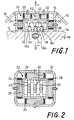
- reference numeral 10 designates a box-like main frame of a pulse wave detecting apparatus, which has an opening 12 at its lower end.
- the apparatus is provided with straps or bands 16 secured to the housing 10, so that the apparatus is removably held on a skin 14 of a wrist 18 of a human being such that the lower end face defining the opening 12 is held in contact with the skin of the wrist 18.
- the main frame 10 accommodates a presser member 32 which is supported by six bellows 20, 22, 24, 26, 28 and 30 also accommodated in the housing 10, such that the presser member 32 is movable relative to the main frame 10.
- the housing frame 10 is positioned on the wrist 18 such that the presser member 32 is located just above the radial artery 34.
- the presser member 32 includes a box-like housing member 38 which has a bottom wall 36 adapted to contact the skin 14 of the wrist 18, and a lid member 40 which closes an upper open end of the housing member 38. These housing member 38 and lid member 40 cooperate with each other to provide a housing structure of the presser member 32. Within this housing struture, there are disposed three oscillating plates 42, 44 and 46.
- each of the three oscillating plates 42, 44, 46 has relatively thick lateral end portions at which the plate is secured to the housing member 38, and a relatively thin inner portion which is elastically deformable and displaceable in a direction of thickness.
- strain gauges 48, 50, 52 are provided on the upper surfaces of the oscillating plates 42, 44, 46.
- Each oscillating plate 42, 44, 46 has a contact element 54, 56, 58 as an integral part thereof, which extends from the lower surface of the thin inner portion indicated above.
- Each contact element 54, 56, 58 takes the form of a cylinder whose diameter is smaller than that of the radial artery 34.
- the contact elements 54, 56, 58 extend through holes 36a, 36b, 36c formed through the thickness of the bottom wall of the housing member 38, such that there exists a small clearance between each contact element and the surface defining the corresponding hole.
- the contact elements 54, 56, 58 may be displaced in the vertical direction relative to the bottom wall of the housing member 38.
- the oscillating plates 42, 44, 46 are so dimensioned and positioned such that the free ends of the contact elements 54, 56, 58 are substantially flush with the lower end face of the housing member 38, so that the ends contact the skin 14 when the detecting apparatus is set on the wrist 18.
- the substantially enclosed space within the housing structure 38, 40 of the presser member 32 communicates with the ambient atmosphere, through an aperture 60 formed through the lid member 40, and an aperture 62 formed through the top wall of the main frame 10. These apertures 60, 62 permit the contact elements 54, 56, 58 of the oscillating plates 42, 44, 46 to be oscillated with high sensitivy, in response to the blood pressure pulsations of the radial artery 34.
- Each of the bellows 20, 22, 24, 26, 28 and 30 is air-tightly secured at its opposite ends, to the inner surface of the main frame 10 and the outer surface of the housing structure 38, 40 of the presser member 32.
- These bellows 20, 22, 24, 26, 28 and 30 communicate with respective conduits, through which are applied air pressures which are controlled by corresponding pressure regulating valves 64, 66, 68, 70, 72 and 74 illustrated in Fig. 4.
- These pressure regulating valves are connected to a suitable pressure source not shown.
- the two bellows 20 and 22 are interposed between the inner surface of the upper wall of the main frame 10 and the upper surface of the top wall of the housing structure of the presser member 32 (i.e., upper surface of the lid member 40).
- the two bellows 20, 22 are spaced apart from each other in the right and left direction as seen in Fig. 1, in a direction perpendicular to the radial artery 34, when the main frame 10 of the instant apparatus is set in position on the wrist 18. If the levels of the air pressures applied to these two bellows 20, 22 are equal to each other, the presser member 32 pressed on the skin 14 is held substantially parallel to the surface of the skin 14. However, the presser member 32 is inclined relative to the skin 14 in a plane perpendicular to the artery 34, if the air pressures applied to the bellows 20, 22 are different from each other.
- the main frame 10, and the housing member 38 of the presser member 32 both have a square shape as seen in the cross section of Fig. 2.
- Each of the four bellows 24, 26, 28 and 30 is disposed between the opposite inner and outer surfaces of the corresponding sides of the main frame 10 and the housing member 38. Described more specifically, each of the bellows 24, 26 is interposed between the corresponding sides of the main frame 10 and the housing member 38, which are spaced apart from each other in the direction perpendicular to the artery 34, when the main frame 10 is set in position on the wrist 18.
- each of the bellows 28 and 30 is interposed between the corresponding sides which are spaced apart from each other in the direction parallel to the artery 34.
- the presser member 32 is held in a substantially middle position within the main frame 10, in the direction perpendicular to the artery 34, i.e., in the right and left direction of Fig. 2. However, if the air pressures applied to these bellows 24, 26 are different, the presser member 32 is moved relative to the main frame 10 or to the skin 14 in the direction perpendicular to the artery 34.
- the presser member 32 is held in a substantially middle position within the main frame 10, in the direction parallel to the artery 34, i.e., in the vertical direction of Fig. 2. However, if the air pressures applied to these bellows 28, 30 are different, the presser member 32 is moved relative to the main frame 10 or to the skin 14 in the direction parallel to the artery 34.
- the electric signals generated from the strain gauges 48, 50, 52 are applied to a control device 76 as shown in Fig. 4.
- This control device 76 which is constituted by a microcomputer in this specific embodiment, is adapted to apply controlled drive signals to the pressure regulating valves 64, 66, 68, 70, 72, 74, based on the electric signals received from the strain gauges 48, 50, 52, so that the air pressures to be applied to the respective bellows 20, 22, 24, 26, 28, 30 are suitably regulated.
- the control device 76 is adapted to control a display and recording device 78, to indicate and record a pulse wave of the radial artery 34, based on the electric signal from the intermediate strain gauge 50.
- the main frame 10 is attached to the wrist 18 by the straps 16, such that the presser member 32 is positioned right above the radial artery 34.
- the contact element 56 of the intermediate oscillating plate 44 assigned to sense the pulse wave of the artery 34 be exactly aligned with the artery 34.
- control device 76 commences to control the first and second pressure regulating valves 64, 66, for applying the same air pressures to the bellows 20, 22, in order to force the bottom wall 36 and the contact elements 54, 56, 58 of the presser member 32 against the skin 14.
- the contact elements 54, 56, 58 are oscillated in response to blood pressure pulsations of the artery 34, whereby the strain gauges 48, 50, 52 produce electric signals indicative of their oscillatory motions, which represent the pulse wave of the artery 34.
- Amplitudes of the electric signals produced by the three strain gauges 48, 50, 52 differ from each other, depending upon the positions of the pressed contact elements 54, 56, 58 relative to the artery 34. Certainly, the electric signal produced by one of the strain gauges 48, 50, 52 which is closest to the artery 34 has the largest amplitude.
- the control device 76 operates to control the third and fourth pressure regulating valves 68, 70, based on the amplitudes of the electric signals received from the strain gauges 48, 50, 52, in order to adjust the air pressures applied to the bellows 24 and 26, and to thereby move the presser member 32 relative to the artery 34, to a position in which the electric signal from the intermediate strain gauge 50 has the largest amplitude, while the electric signals from the two outer strain gauges 48, 52 have comparatively low, substantially equal amplitudes.
- the contact element 56 of the intermediate oscillating plate 44 is positioned right above the artery 34, for achieving accurate detection of the pulse wave of the artery 34.
- the amplitude of the electric signal generated by the strain gauge 50 due to the oscillatory deformation of the contact element 56 thus positioned right above the radial artery 34 also varies depending upon the position of the presser member 32 in the direction parallel to the artery 34, and upon the specific posture of the presser member 32 relative to the artery, because of the presence of the radius and hypodermal tissue of the wrist 18.
- the control device 76 operates to control the fifth and sixth pressure regulating valves 72, 74, for adjusting the air pressures applied to the bellows 28, 30 and thereby moving the presser member 32 in the longitudinal direction of the artery 34, to a position in which the electric signal from the strain gauge 50 has the largest amplitude.
- first and second valves 64, 66 are controlled to adjust the pressures applied to the bellows 20, 22, for adjusting the posture or angle of inclination of the presser member 32 in a plane perpendicular to the artery 34, so that the electric signal from the strain gauge 50 has the largest amplitude.
- the positions of the contact element 56 in the directions perpendicular and parallel to the artery 34, and its posture relative to the skin 14, are adjusted relative to the main frame 10, so that the amplitude of the electric signal produced by the intermediate strain gauge 50 is the largest.
- the control device 76 controls the first and second valves 64, 66 to adjust the pressures applied to the bellows 20, 22, in order to change the posture or inclination of the presser member 32 in the plane of Fig. 1 (perpendicular to the extending direction of the artery 34), so that the electric signal of the strain gauge 50 has the largest amplitude. If this adjustment does not permit the strain gauge 50 to have an electric signal having the largest amplitude, the control device 76 commands the display and recording device 78, to provide an indication of this fact, advising the user that the main frame 10 must be re-positioned on the wrist 18.
- the control device 76 be operated to reduce the air pressures applied to the bellows 20, 22, or stop the supply of the pressuzied air to these bellows, or alternatively connect the bellows 20, 22 to a vacuum source, for reducing the depression force of the presser member 32 to a lower, zero, or negative level, before the presser member 32 is moved relative to the skin 14. After this adjustment of the presser member 32 is completed, the presser member 32 is again depressed against the skin 14 by the bellows 20, 22, and the electric signals from the strain gauges 48, 50, 52 are received by the control device 76.
- the air pressures applied to the bellows 20, 22 are equally raised or lowered, to adjust the depression force of the presser member 32 against the skin 14, so that the electric signal received from the strain gauge 50 has the larget amplitude.
- the artery 34 is completely occluded and provides no pulse wave.
- the pulse wave to be transmitted to the contact element 56 is weak if the depression force is excessively small.
- the amplitude of the electric signal produced by the strain gauge 50 is the largest when the artery 34 depressed by the presser member 32 takes an oval form in the transverse cross section.
- the electric signal produced by the strain gauge 50 of the thus oriented presser member 32 is continuously received by the control device 76, and the device 76 commands the display and recording device 78 to display and record a pulse wave of the artery 34 represented by the received signal.
- the control device 76 is adapted to diagnose the working conditions of the heart of the subject based on the detected waveform, and/or determine the maximum and minimum (systolic and diastolic) blood pressures based on the maximum and minimum values of the pulse wave.
- the control device 76 continues to compare the received electric signals from the three strain gauges 48, 50, 52 with each other, to adjust the air pressures applied to the bellows 24, 26, for moving the presser member 32 if the contact element 56 is dislocated due to movement of the wrist 18 of the subject, so that the contact element 56 is always held in the optimum position in the direction perpendicular to the artery 34.
- the three strain gauges 48, 50, 52 are provided, the direction in which the presser member 32 is dislocated can be readily detected, and the presser member 32 can be rapidly re-located into position.
- the positions and posture of the presser member 32 relative to the skin 14 are adjusted in the present embodiment, so as to hold the contact element 56 in an optimum position for detecting a pulse wave of the artery 34 with high accuracy.
- the detecting accuracy can be improved, because the instant embodiment is capable of adjusting the position of the presser member 32 in the longitudinal direction of the artery 34, and the posture of the presser member 32 relative to the skin 34, as well as the position of the presser member 32 in the direction perpendicular to the artery 34.
- the contact elements 54, 56, 58 may have a larger size, than those used in the conventional detecting apparatus wherein an element for detecting the pulse wave is selected from among a multiplicity of contact elements which are not movable relative to the artery 34 once the apparatus is set.
- the oscillating plates 44, 46, 48 having the contact elements 54, 56, 58, and the strain gauges 48, 50, 52 can be comparatively easily manufactured.
- the relatively large strain gauges 48, 50, 52 assure comparatively higher detecting accuracy, than the conventionally used strain gauges or other converter means which are relatively small in size.
- the comparatively high detecting accuracy of the instant detecting apparatus is also assured even when the presser member 32 is more or less disclocated due to movement of the subject, since the positions and posture of the presser member 32 are adjusted while the apparatus is in the process of detecting the pulse wave.
- the control device 76 can readily determine the direction of dislocation of the presser member 32, and therefore rapidly re-orient the dislocated presser member 32.
- the bellows 20, 22, 24, 26, 28 and 30, pressure regulating valves 64, 66, 68, 70, 72 and 74, and control device 76 cooperate to provide positioning means for moving the presser member 32 relative to the subject. Further, the bellows 20, 22, pressure regulating valves 64, 66 and control device 76 also function as pressing means for forcing the presser member 32 against the subject.
- strain gauges 48, 50, 52 adapted to sense the oscillatory deformation of the oscillating plates 42, 44, 46 may be semiconductor strain gauges, or may be replaced by various other means known for detecting a pulse wave.
- An example of an alternative detecting arrangement is illustrated in Fig. 5, in which a single-crystal silicon chip 80 is secured to the housing member 38 so as to form a bottom wall in place of the bottom wall 36 of the preceding embodiment.
- the semiconductor chip 80 is provided at its thin-walled portions with three piezoelectric elements 82, 84, 86.
- This silicon chip 80 is adapted such that blood pressure pulsations of the artery 34 are transmitted to the thin-walled portions and the corresponding piezoelectric elements 82, 84, 86 through three rubber fillers 88, 90, 92, respectively. More specifically, the thin-wall portions of the chip 80 define three recesses which are open in the outer surface of the chip. The rubber fillers 88, 90, 92 are secured to the chip 80 such that the fillers fill the respective recesses. Resulting oscillatory pressure vibrations of the thin-walled portions of the chip 80 are converted by the piezoelectric elements 82, 84, 86 into corresponding electric signals. In this modified embodiment of Fig. 5, the rubber fillers 88, 90, 92 correspond to the contact elements of the presser member. It is desirable that the diameter of each filler 88, 90, 92 be smaller than the diameter of the artery 34.
- the pneumatically operated bellows 20, 22, 24, 26, 28 and 30 are used to move the presser member 32 relative to the main frame 10 along the mutually perpendicular three axes.
- these bellows may be replaced by feed screws driven by motors to position the presser member 32, or replaced by springs or elastomeric members to force the presser member 32 against the skin 14.
- the principle of the present invention may be practiced, provided that the contact element 56 may be moved at least in the direction perpendicular to the artery 34, so as to be positioned right above the artery 34 and depressed against the skin 14.
- the positions and posture of the presser member 32 are adjusted by controlling the pressures of the air to be supplied to the bellows 20, 22, 24, 26, 28, 30, it is possible to positively discharge the pressurized air from the bellows, for positioning or orienting the presser member 32.
- the three oscillating plates 42, 44, 46 are used, and the pulse wave detection is effected based on the oscillatory deformation of the intermediate oscillating plate 44.
- the principle of the invention may be practiced even if a single oscillating plate is provided.
- the pulse wave detection is not necessarily based on the oscillation of the intermediate plate 44, but may be achieved based on one of the three oscillating plates 42, 44, 46 whose output signal has the largest amplitude.
- the presser member 32 may include four or more oscillating plates, or the chip 80 may have four or more piezoelectric elements, as far as one of the plates or elements is brought into an optimum pulse wave detecting position by moving the presser member 32 or the chip 80 relative to the main frame 10 of the apparatus.
- the positional adjustment of the presser member 32 in the illustrated embodiments is based on the amplitude of the electric signals generated by the strain gauges 48, 50, 52, the adjustment may be achieved with the intensity of the signals taken into account.
- each oscillating plates 42, 44, 46 has the single strain gauge 48, 50, 52 so that the deformation of the plate is converted into an electric signal.
- each oscillating plate may have two or four strain gauges arranged in a bridge circuit to provide a single electric signal.
- the diameter of the contact elements 54, 56, 58, or the diameter of the rubber fillers 88, 90, 92 is smaller than the diameter of the artery 34, it is possible that the diameter of these contact elements or rubber fillers exceeds that of the artery 34. Further, the contact elements or fillers may have a suitable configuration other than a cylinder or disc.
- the illustrated embodiments are adapted to detect the pulse wave of the radial artery 34
- the present invention may be embodied as an apparatus for detecting a pulse wave of the other arterial vessels, such as the carotid artery.
Landscapes
- Health & Medical Sciences (AREA)
- Life Sciences & Earth Sciences (AREA)
- Cardiology (AREA)
- Medical Informatics (AREA)
- Surgery (AREA)
- Engineering & Computer Science (AREA)
- Biomedical Technology (AREA)
- Heart & Thoracic Surgery (AREA)
- Physics & Mathematics (AREA)
- Molecular Biology (AREA)
- Pathology (AREA)
- Animal Behavior & Ethology (AREA)
- General Health & Medical Sciences (AREA)
- Public Health (AREA)
- Veterinary Medicine (AREA)
- Biophysics (AREA)
- Physiology (AREA)
- Vascular Medicine (AREA)
- Measuring Pulse, Heart Rate, Blood Pressure Or Blood Flow (AREA)
Claims (11)
- Pulswellenmeßgerät zum Erfassen einer Blutdruck-Pulswelle einer Schlagader (34) eines Patienten aufgrund einer Schwingungsbewegung von mindestens einem Berührungselement (54, 56, 58, 88, 90, 92), das gegen eine Oberfläche (14) eines Körperteils (18) des Patienten derart andrückbar ist, daß das mindestens eine Berührungselement entsprechend dem Pulsieren der Schlagader schwingt, wobei das Meßgerät einen Hauptrahmen (10) zur Halterung des mindestens einen Berührungselementes (54, 56, 58, 88, 90, 92) in der Weise, daß das mindestens eine Berührungselement in bezug auf den Hauptrahmen bewegbar ist, der an der Oberflache (14) des Körperteils (18) angebracht ist, und eine Andruckvorrichtung (20, 22, 64, 66, 76) für das Bewegen des mindestens einen Berührungselements in bezug auf den Hauptrahmen (10) in einer Richtung zu der Oberfläche (14) hin zum Andrücken des mindestens einen Berührungselementes gegen die Oberfläche aufweist, gekennzeichnet durch eine Einstellvorrichtung (20, 22, 24, 26, 28, 30, 64, 66, 68, 70, 72, 74, 76), die zumindest zum Bewegen und Einstellen des mindestens einen Berührungselementes in bezug auf den Hauptrahmen (10) und entlang der Oberfläche (14) in einer zur Richtung des Verlaufs der Schlagader (34) senkrechten Richtung betätigbar ist, um dadurch mindestens ein Berührungselement richtig über der Schlagader anzusetzen, und mindestens einen Fühler (48, 50, 52; 82, 84, 86) zum Umsetzen der Schwingungsbewegung des mindestens einen Berührungselementes (54, 56, 58; 88, 90, 92) in ein elektrisches Signal, wobei die Einstellvorrichtung (20, 22, 24, 26, 28, 30, 64, 66, 68, 70, 72, 74, 76) das mindestens eine Berührungselement gemäß dem von dem mindestens einen Fühler erzeugten elektrischen Signal korrekt über der Schlagader ansetzt.
- Pulswellenmeßgerät nach Anspruch 1, bei dem das mindestens eine Berührungselement aus mindestens drei Berührungselementen (54, 56, 58; 88, 90. 92) besteht, die in einer zu der Oberfläche (14) parallelen Ebene in gegenseitigen Abständen in der zu der Schlagader (34) senkrechten Richtung angeordnet sind, wobei die Einstellvorrichtung (20, 22, 24, 26, 28, 30, 64, 66, 68, 70, 72, 74, 76) zum richtigen Einstellen eines mittleren der mindestens drei Berührungselemente über der Schlagader (34) aufgrund der Schwingungsbewegungen der mindestens drei Berührungselementee betätigbar ist.
- Pulswellenmeßgerät nach Anspruch 1, bei dem die Einstellvorrichtung (20, 22, 24, 26, 28, 30, 64, 66, 68, 70, 72, 74, 76) auch zum Bewegen des mindestens einer Berührungselementes (54, 56, 58; 88, 90, 92) entlang der Oberfläche (14) in einer zu der Richtung des Verlaufs der Schlagader (34) parallelen Richtung und zum Einstellen eines Neigungswinkels des mindestens einen Berührungselementes in bezug auf die Oberfläche (14) in einer zu der Richtung des Verlaufs der Schlagader senkrechten Ebene betätigbar ist.
- Pulswellenmeßgerät nach Anspruch 1, das ferner ein Andruckteil (32) enthält, welches (a) eine Gehäuseanordnung (38, 40), die bewegbar in dem Hauptrahmen (10) gelagert und aufgenommen ist, (b) mindestens eine Schwingplatte (42, 44, 46), die fest in der Gehäuseanordnung (38, 40) angeordnet ist, und (c) mindestens einen jeweils an der mindestens einen Schwingplatte angebrachten Dehnungsmeßstreifen (48, 50, 52) enthält, wobei die Gehäuseanordnung (38, 40) eine Bodenwand (36) hat, durch die hindurch mindestens eine Öffnung (36a, 36b, 36c) ausgebildet ist, wobei das mindestens eine Berührungselement (54, 56, 58) durch eine entsprechende Öffnung hindurchragt und derart an einer entsprechenden Schwingplatte befestigt ist, daß das Berührungselement in der entsprechenden Öffnung bewegbar ist und an einem freien Ende zur Berührung mit der Oberfläche (14) des Körperteils (18) freiliegt, wobei die Andruckvorrichtung (20, 22, 64, 66, 76) zum Bewegen der Gehäuseanordnung (38, 40) zu der Oberfläche (14) hin und dadurch zum Anpressen des freien Endes des jeweiligen Berührungselementes gegen die Oberfläche (14) betätigbar ist.
- Pulswellenmeßgerät nach Anspruch 4, bei dem die Gehäuseanordnung (38, 40) ein kastenartiges Gehäuseteil (38) mit der Bodenwand (36) und ferner ein Deckelteil (40) enthält, das eine von der Bodenwand entfernte Öffnung abschließt.
- Pulswellenmeßgerät nach Anspruch 5, bei dem die Andruckvorrichtung (20, 22, 64, 66, 76) Faltenbalge (20, 22) enthält, die zwischen eine Innenfläche des Hauptrahmens (10) und das Deckelteil (40) der Gehäuseanordnung des Andruckteils (32) gesetzt sind, um die Gehäuseanordnung gegen die Oberfläche (14) des Körperteils (18) zu drücken.
- Pulswellenmeßgerät nach Anspruch 4, bei dem die Einstellvorrichtung (20, 22, 24, 26, 28, 30, 64, 66, 68, 70, 72, 74) Faltenbalge (24, 26) enthält, die zwischen Innenflächen des Hauptrahmens (10) und gegenüberliegende Außenflächen der Gehäuseanordnung (38, 40) eingefügt sind, um das Andruckteil (32) entlang der Oberfläche (14) in der zur Richtung des Verlaufs der Schlagader (34) senkrechten Richtung zu bewegen.
- Pulswellenmeßgerät nach Anspruch 7, bei dem die Einstellvorrichtung (20, 22, 24, 26, 28, 30, 64, 66, 68, 70, 72, 74) ferner Faltenbalge (20, 22) enthält, die zwischen eine von der Bodenwand (36) abliegende Außenfläche einer oberen Wand der Gehäuseanordnung (38, 40) und eine gegenüberliegende Innenfläche des Hauptrahmens (10) eingefügt sind, um einen Neigungswinkel des Andruckteils (32) in bezug auf die Oberfläche (14) des Körperteils (18) in einer zu der Richtung des Verlaufs der Schlagader (34) senkrechten Ebene zu verändern.
- Pulswellenmeßgerät nach Anspruch 1, das ferner ein Andruckteil (32) aufweist, welches (a) eine Gehäuseanordnung (38, 40), die bewegbar in dem Hauptrahmen (10) gelagert und aufgenommen ist, (b) ein Halbleiterplättchen (80), das an der Gehäuseanordnung derart angebracht ist, daß es eine Bodenwand der Gehäuseanordnung bildet, wobei das Halbleiterplättchen mindestens einen dünnwandigen Bereich hat, der eine an einer Außenfläche der Bodenwand offene Ausnehmung (80a, 80b, 80c) bildet, und mindestens ein piezoelektrisches Element (82, 84, 86) enthält, das jeweils an einem dünnwandigen Bereich des Halbleiterplättchens angebracht ist, wobei das mindestens eine Berührungselement aus mindestens einer Gummifüllung (88, 90, 92) besteht, die jeweils die Ausnehmung in einem dünnwandigen Bereich des Halbleiterplättchens ausfüllt, so daß die Blutdruckpulswelle der Schlagader (34) über die Gummifüllung zu dem dünnwandigen Bereich des Halbleiterplättchens übertragen wird, wobei die Andruckvorrichtung (20, 22, 64, 66, 76) zum Bewegen der Gehäuseanordnung (38, 40) zu der Oberfläche (14) des Körperteils (18) und dadurch zum Andrücken der mindestens einen Gummifüllung gegen die Oberfläche (14) betätigbar ist.
- Pulswellenmeßgerät nach Anspruch 1, bei dem die Einstellvorrichtung (20, 22, 24, 26, 28, 30, 64, 66, 68, 70, 72, 74, 76) pneumatisch betätigte Stellglieder (24, 26) zum Bewegen des mindestens einen Berührungselementes (54, 56, 58; 88, 90, 92) in der zu der Richtung des Verlaufs der Schlagader (34) senkrechten Richtung und mit den Stellgliedern verbundene Druckregelventile (68, 70) zum Regeln der Luftdrücke für das Beaufschlagen der Stellglieder enthält, wobei die Einstellvorrichtung ferner eine Steuereinrichtung (76) zum Steuern der Druckregelventile aufweist.
- Pulswellenmeßgerät nach Anspruch 2, das ferner mindestens drei Fühler (48, 50, 52; 82, 84, 86) zum Umsetzen der Schwingbewegungen des entsprechenden der mindestens drei Berührungselemente (54, 56, 58; 88, 90, 92) in jeweilige elektrische Signale und eine Anzeigevorrichtung zur Anzeige der Pulswelle der Schlagader aufgrund des von dem dem mittleren der mindestens drei Berührungselemente entsprechenden Fühler erzeugten elektrischen Signals aufweist.
Applications Claiming Priority (2)
| Application Number | Priority Date | Filing Date | Title |
|---|---|---|---|
| JP62109594A JPH082350B2 (ja) | 1987-05-02 | 1987-05-02 | 脈波検出装置 |
| JP109594/87 | 1987-05-02 |
Publications (2)
| Publication Number | Publication Date |
|---|---|
| EP0289700A1 EP0289700A1 (de) | 1988-11-09 |
| EP0289700B1 true EP0289700B1 (de) | 1993-06-16 |
Family
ID=14514225
Family Applications (1)
| Application Number | Title | Priority Date | Filing Date |
|---|---|---|---|
| EP88101175A Expired - Lifetime EP0289700B1 (de) | 1987-05-02 | 1988-01-27 | Gerät zur Anzeige von Pulswellen |
Country Status (5)
| Country | Link |
|---|---|
| US (1) | US4784152A (de) |
| EP (1) | EP0289700B1 (de) |
| JP (1) | JPH082350B2 (de) |
| CA (1) | CA1327387C (de) |
| DE (1) | DE3881754T2 (de) |
Cited By (1)
| Publication number | Priority date | Publication date | Assignee | Title |
|---|---|---|---|---|
| CN102499663A (zh) * | 2011-06-09 | 2012-06-20 | 李钢坤 | 一种心率传感器的心率振子 |
Families Citing this family (44)
| Publication number | Priority date | Publication date | Assignee | Title |
|---|---|---|---|---|
| JPH0428562Y2 (de) * | 1988-02-23 | 1992-07-10 | ||
| WO1990002512A1 (en) * | 1988-09-12 | 1990-03-22 | Hon Edward H | Improved apparatus for measuring continuous boold pressure |
| US4947855A (en) * | 1989-02-20 | 1990-08-14 | Colin Electronics Co., Ltd. | Blood pressure measuring apparatus |
| JP2798764B2 (ja) * | 1990-01-09 | 1998-09-17 | コーリン電子株式会社 | 半導体圧脈波センサ |
| US5154680A (en) * | 1990-03-27 | 1992-10-13 | Rutgers University | Pressure waveform monitor |
| US5179956A (en) * | 1990-07-06 | 1993-01-19 | Colin Electronics Co., Ltd. | Contact pressure sensor |
| JP2524278Y2 (ja) * | 1990-09-10 | 1997-01-29 | コーリン電子株式会社 | 脈波検出装置 |
| US5240007A (en) * | 1991-05-14 | 1993-08-31 | Ivac Corporation | Apparatus and method for moving a tissue stress sensor for applanating an artery |
| US5176143A (en) * | 1991-06-17 | 1993-01-05 | Colin Electronics Company, Ltd. | Tonometer transducer positioning system |
| US5263484A (en) * | 1992-02-13 | 1993-11-23 | Ivac Corporation | Method of determining which portion of a stress sensor is best positioned for use in determining intra-arterial blood pressure |
| US5273046A (en) * | 1992-04-15 | 1993-12-28 | Ivac Corporation | Method of determining optimum artery applanation |
| FR2700683B1 (fr) * | 1993-01-28 | 1995-04-14 | Univ Rennes | Dispositif de reconnaissance de phases de sommeil, et application correspondante. |
| US5494043A (en) * | 1993-05-04 | 1996-02-27 | Vital Insite, Inc. | Arterial sensor |
| US6371921B1 (en) | 1994-04-15 | 2002-04-16 | Masimo Corporation | System and method of determining whether to recalibrate a blood pressure monitor |
| US5904654A (en) * | 1995-10-20 | 1999-05-18 | Vital Insite, Inc. | Exciter-detector unit for measuring physiological parameters |
| JP3571394B2 (ja) * | 1995-01-09 | 2004-09-29 | コーリンメディカルテクノロジー株式会社 | 圧脈波検出装置 |
| JPH08187230A (ja) * | 1995-01-10 | 1996-07-23 | Nippon Colin Co Ltd | 圧脈波検出装置 |
| DE19542019C1 (de) * | 1995-11-10 | 1997-03-06 | Fraunhofer Ges Forschung | Sensor zum nichtinvasiven und kontinuierlichen Erfassen der arteriellen Pulswellenlaufzeit |
| US6027452A (en) | 1996-06-26 | 2000-02-22 | Vital Insite, Inc. | Rapid non-invasive blood pressure measuring device |
| US6491647B1 (en) | 1998-09-23 | 2002-12-10 | Active Signal Technologies, Inc. | Physiological sensing device |
| GB0008883D0 (en) * | 2000-04-12 | 2000-05-31 | Univ Ulster | Bodily flow measuring system |
| JP5110751B2 (ja) * | 2000-08-24 | 2012-12-26 | セイコーインスツル株式会社 | 超音波診断装置 |
| JP3772691B2 (ja) * | 2001-05-09 | 2006-05-10 | オムロンヘルスケア株式会社 | 脈波検出装置 |
| KR100416046B1 (ko) * | 2001-07-03 | 2004-01-24 | 광주과학기술원 | 공압시스템을 이용한 맥파검출장치 |
| US20030107487A1 (en) * | 2001-12-10 | 2003-06-12 | Ronen Korman | Method and device for measuring physiological parameters at the wrist |
| US6730038B2 (en) * | 2002-02-05 | 2004-05-04 | Tensys Medical, Inc. | Method and apparatus for non-invasively measuring hemodynamic parameters using parametrics |
| JP2004208711A (ja) * | 2002-12-26 | 2004-07-29 | Colin Medical Technology Corp | 圧脈波センサおよび圧脈波解析装置 |
| US7341561B2 (en) * | 2003-05-30 | 2008-03-11 | Casio Computer Co., Ltd. | Wrist-worn high-accuracy pulsation measuring apparatus |
| DE102004062435A1 (de) * | 2004-12-20 | 2006-06-29 | Braun Gmbh | Verfahren und Vorrichtung zur nicht-invasiven Detektion des Blutflusses und davon abhängiger Parameter in Arterien, insbesondere der arteriellen Wellenform und des Blutdruckes |
| US20060200028A1 (en) * | 2005-03-04 | 2006-09-07 | Medwave, Inc. | Sensor-based apparatus and method for portable noninvasive monitoring of blood pressure |
| KR101534590B1 (ko) * | 2008-11-12 | 2015-07-08 | 삼성전자주식회사 | 가압 모듈 및 이를 구비한 혈압 측정 장치 |
| CN103622671B (zh) * | 2013-11-05 | 2016-09-07 | 深圳市视聆科技开发有限公司 | 非接触生理或周期性作用力信号采集装置及垫子 |
| WO2015088909A1 (en) * | 2013-12-09 | 2015-06-18 | Etymotic Research, Inc. | System for providing an applied force indication |
| KR101646439B1 (ko) * | 2015-01-26 | 2016-08-08 | 울산대학교 산학협력단 | 혈액순환장애 측정 장치 및 그 방법 |
| US10842396B2 (en) * | 2015-04-17 | 2020-11-24 | Taiyo Yuden Co., Ltd. | Vibration waveform sensor and waveform analysis device |
| JP6798135B2 (ja) | 2016-04-15 | 2020-12-09 | オムロンヘルスケア株式会社 | 脈波検出装置及び生体情報測定装置 |
| JP6662166B2 (ja) * | 2016-04-15 | 2020-03-11 | オムロンヘルスケア株式会社 | 脈波検出装置、生体情報測定装置、脈波検出装置の制御方法、及び、脈波検出装置の制御プログラム |
| JP6786856B2 (ja) * | 2016-04-15 | 2020-11-18 | オムロンヘルスケア株式会社 | 脈波検出装置、生体情報測定装置、脈波検出装置の制御方法、及び、脈波検出装置の制御プログラム |
| JP6682979B2 (ja) | 2016-04-15 | 2020-04-15 | オムロンヘルスケア株式会社 | 脈波検出装置、生体情報測定装置、脈波検出装置の制御方法、及び、脈波検出装置の制御プログラム |
| JP6631376B2 (ja) * | 2016-04-15 | 2020-01-15 | オムロンヘルスケア株式会社 | 脈波検出装置、生体情報測定装置、脈波検出装置の制御方法、及び、脈波検出装置の制御プログラム |
| US20180199830A1 (en) * | 2017-01-13 | 2018-07-19 | Microsoft Technology Licensing, Llc | Wearable tonometer with resiliently deformable pad |
| GB2563578B (en) * | 2017-06-14 | 2022-04-20 | Bevan Heba | Medical devices |
| JP6970605B2 (ja) * | 2017-12-19 | 2021-11-24 | オムロンヘルスケア株式会社 | 血圧推定装置 |
| CN119700060A (zh) * | 2024-12-09 | 2025-03-28 | 北京理工大学 | 脉搏检测系统、方法及可穿戴式设备 |
Family Cites Families (7)
| Publication number | Priority date | Publication date | Assignee | Title |
|---|---|---|---|---|
| FR1421820A (fr) * | 1965-01-14 | 1965-12-17 | Inst Prueffeld Fuer Elek Sche | Commande à fluide comprimé, notamment pour appareils électrils électriques de commutation |
| US3880145A (en) * | 1972-10-02 | 1975-04-29 | Stein Paul D | Method and apparatus for continuously monitoring blood pressure |
| US4423738A (en) * | 1977-11-04 | 1984-01-03 | Sri International | Noninvasive blood pressure monitoring transducer |
| US4307728A (en) * | 1979-12-31 | 1981-12-29 | Walton Charles A | Portable device for measuring heartbeat rate with compensation for extraneous signals |
| US4409983A (en) * | 1981-08-20 | 1983-10-18 | Albert David E | Pulse measuring device |
| US4561447A (en) * | 1983-01-14 | 1985-12-31 | Nippon, Colin Co., Ltd. | Apparatus and method of detecting arterial pulse wave |
| DE3310700A1 (de) * | 1983-03-24 | 1984-09-27 | Theodor Hymmen Kg, 4800 Bielefeld | Vorrichtung zum aufbringen einer flaechenpressung auf fortschreitende werkstuecke |
-
1987
- 1987-05-02 JP JP62109594A patent/JPH082350B2/ja not_active Expired - Fee Related
- 1987-12-23 US US07/137,347 patent/US4784152A/en not_active Expired - Lifetime
-
1988
- 1988-01-27 DE DE88101175T patent/DE3881754T2/de not_active Expired - Fee Related
- 1988-01-27 EP EP88101175A patent/EP0289700B1/de not_active Expired - Lifetime
- 1988-03-24 CA CA000562374A patent/CA1327387C/en not_active Expired - Fee Related
Cited By (1)
| Publication number | Priority date | Publication date | Assignee | Title |
|---|---|---|---|---|
| CN102499663A (zh) * | 2011-06-09 | 2012-06-20 | 李钢坤 | 一种心率传感器的心率振子 |
Also Published As
| Publication number | Publication date |
|---|---|
| EP0289700A1 (de) | 1988-11-09 |
| CA1327387C (en) | 1994-03-01 |
| JPS63275320A (ja) | 1988-11-14 |
| US4784152A (en) | 1988-11-15 |
| DE3881754T2 (de) | 1993-10-28 |
| JPH082350B2 (ja) | 1996-01-17 |
| DE3881754D1 (de) | 1993-07-22 |
Similar Documents
| Publication | Publication Date | Title |
|---|---|---|
| EP0289700B1 (de) | Gerät zur Anzeige von Pulswellen | |
| US4830017A (en) | Automatic positioning system for continuous blood pressure monitor transducer | |
| US5119822A (en) | Pulse wave detecting apparatus | |
| CA1331788C (en) | Blood pressure monitoring system | |
| JP2664982B2 (ja) | 血圧モニタ装置 | |
| US5941828A (en) | Hand-held non-invasive blood pressure measurement device | |
| US4836213A (en) | Pressure control system for continuous blood pressure monitor transducer | |
| US6645156B2 (en) | Continuous blood-pressure monitoring apparatus | |
| US6602198B2 (en) | Automatic blood-pressure measuring apparatus | |
| US5439002A (en) | Blood pressure monitor system | |
| US4893631A (en) | Active element selection for continuous blood pressure monitor transducer | |
| US5590661A (en) | Blood pressure measuring apparatus | |
| JPS63293424A (ja) | 脈波検出装置 | |
| JP2505462B2 (ja) | 脈波連続測定装置 | |
| JP2572088B2 (ja) | 脈波検出装置 | |
| JPH0436806Y2 (de) | ||
| JPH0434808Y2 (de) | ||
| JPH0532085Y2 (de) | ||
| JPH0434807Y2 (de) | ||
| JP2602465Y2 (ja) | 圧脈波検出装置 | |
| JP2516634B2 (ja) | 血圧連続測定装置 | |
| JP2613610B2 (ja) | 脈波検出装置 | |
| JPH05192305A (ja) | 血圧測定装置 |
Legal Events
| Date | Code | Title | Description |
|---|---|---|---|
| PUAI | Public reference made under article 153(3) epc to a published international application that has entered the european phase |
Free format text: ORIGINAL CODE: 0009012 |
|
| AK | Designated contracting states |
Kind code of ref document: A1 Designated state(s): CH DE ES FR GB IT LI NL SE |
|
| 17P | Request for examination filed |
Effective date: 19890424 |
|
| 17Q | First examination report despatched |
Effective date: 19910725 |
|
| GRAA | (expected) grant |
Free format text: ORIGINAL CODE: 0009210 |
|
| AK | Designated contracting states |
Kind code of ref document: B1 Designated state(s): CH DE ES FR GB IT LI NL SE |
|
| PG25 | Lapsed in a contracting state [announced via postgrant information from national office to epo] |
Ref country code: NL Effective date: 19930616 Ref country code: IT Free format text: LAPSE BECAUSE OF FAILURE TO SUBMIT A TRANSLATION OF THE DESCRIPTION OR TO PAY THE FEE WITHIN THE PRE;WARNING: LAPSES OF ITALIAN PATENTS WITH EFFECTIVE DATE BEFORE 2007 MAY HAVE OCCURRED AT ANY TIME BEFORE 2007. THE CORRECT EFFECTIVE DATE MAY BE DIFFERENT FROM THE ONE RECORDED.SCRIBED TIME-LIMIT Effective date: 19930616 Ref country code: LI Effective date: 19930616 Ref country code: ES Free format text: THE PATENT HAS BEEN ANNULLED BY A DECISION OF A NATIONAL AUTHORITY Effective date: 19930616 Ref country code: CH Effective date: 19930616 Ref country code: SE Effective date: 19930616 |
|
| REF | Corresponds to: |
Ref document number: 3881754 Country of ref document: DE Date of ref document: 19930722 |
|
| ET | Fr: translation filed | ||
| REG | Reference to a national code |
Ref country code: CH Ref legal event code: PL |
|
| NLV1 | Nl: lapsed or annulled due to failure to fulfill the requirements of art. 29p and 29m of the patents act | ||
| PLBE | No opposition filed within time limit |
Free format text: ORIGINAL CODE: 0009261 |
|
| STAA | Information on the status of an ep patent application or granted ep patent |
Free format text: STATUS: NO OPPOSITION FILED WITHIN TIME LIMIT |
|
| 26N | No opposition filed | ||
| REG | Reference to a national code |
Ref country code: GB Ref legal event code: IF02 |
|
| PGFP | Annual fee paid to national office [announced via postgrant information from national office to epo] |
Ref country code: GB Payment date: 20030107 Year of fee payment: 16 |
|
| PGFP | Annual fee paid to national office [announced via postgrant information from national office to epo] |
Ref country code: FR Payment date: 20030120 Year of fee payment: 16 |
|
| PGFP | Annual fee paid to national office [announced via postgrant information from national office to epo] |
Ref country code: DE Payment date: 20030226 Year of fee payment: 16 |
|
| PG25 | Lapsed in a contracting state [announced via postgrant information from national office to epo] |
Ref country code: GB Free format text: LAPSE BECAUSE OF NON-PAYMENT OF DUE FEES Effective date: 20040127 |
|
| PG25 | Lapsed in a contracting state [announced via postgrant information from national office to epo] |
Ref country code: DE Free format text: LAPSE BECAUSE OF NON-PAYMENT OF DUE FEES Effective date: 20040803 |
|
| GBPC | Gb: european patent ceased through non-payment of renewal fee |
Effective date: 20040127 |
|
| PG25 | Lapsed in a contracting state [announced via postgrant information from national office to epo] |
Ref country code: FR Free format text: LAPSE BECAUSE OF NON-PAYMENT OF DUE FEES Effective date: 20040930 |
|
| REG | Reference to a national code |
Ref country code: FR Ref legal event code: ST |