EP0289701B1 - Fremdgezündete Mehrzylinder-Brennkraftmaschine mit Turbolader - Google Patents
Fremdgezündete Mehrzylinder-Brennkraftmaschine mit Turbolader Download PDFInfo
- Publication number
- EP0289701B1 EP0289701B1 EP88101458A EP88101458A EP0289701B1 EP 0289701 B1 EP0289701 B1 EP 0289701B1 EP 88101458 A EP88101458 A EP 88101458A EP 88101458 A EP88101458 A EP 88101458A EP 0289701 B1 EP0289701 B1 EP 0289701B1
- Authority
- EP
- European Patent Office
- Prior art keywords
- combustion engine
- internal combustion
- supercharged
- air
- distributor
- Prior art date
- Legal status (The legal status is an assumption and is not a legal conclusion. Google has not performed a legal analysis and makes no representation as to the accuracy of the status listed.)
- Expired - Lifetime
Links
Images

Classifications
-
- F—MECHANICAL ENGINEERING; LIGHTING; HEATING; WEAPONS; BLASTING
- F02—COMBUSTION ENGINES; HOT-GAS OR COMBUSTION-PRODUCT ENGINE PLANTS
- F02P—IGNITION, OTHER THAN COMPRESSION IGNITION, FOR INTERNAL-COMBUSTION ENGINES; TESTING OF IGNITION TIMING IN COMPRESSION-IGNITION ENGINES
- F02P7/00—Arrangements of distributors, circuit-makers or -breakers, e.g. of distributor and circuit-breaker combinations or pick-up devices
- F02P7/02—Arrangements of distributors, circuit-makers or -breakers, e.g. of distributor and circuit-breaker combinations or pick-up devices of distributors
- F02P7/04—Arrangements of distributors, circuit-makers or -breakers, e.g. of distributor and circuit-breaker combinations or pick-up devices of distributors having distributors with air-tight casing
-
- F—MECHANICAL ENGINEERING; LIGHTING; HEATING; WEAPONS; BLASTING
- F02—COMBUSTION ENGINES; HOT-GAS OR COMBUSTION-PRODUCT ENGINE PLANTS
- F02P—IGNITION, OTHER THAN COMPRESSION IGNITION, FOR INTERNAL-COMBUSTION ENGINES; TESTING OF IGNITION TIMING IN COMPRESSION-IGNITION ENGINES
- F02P7/00—Arrangements of distributors, circuit-makers or -breakers, e.g. of distributor and circuit-breaker combinations or pick-up devices
- F02P7/02—Arrangements of distributors, circuit-makers or -breakers, e.g. of distributor and circuit-breaker combinations or pick-up devices of distributors
- F02P7/021—Mechanical distributors
Definitions
- the invention relates to a spark-ignited multi-cylinder internal combustion engine with turbocharger according to the preamble of claim 1.
- the inlet pressure to the distributor housing is already above sea level at sea level. This pressure difference ensures that a good flow through the ignition distributor is ensured.
- the distributor housing is arranged in a bypass line to the charge air cooler in such a way that the charge air branched off in front of the charge air cooler flows back into the charge air line after flowing through the distributor housing behind the charge air cooler.
- the pressure difference at the charge air cooler is available for the flow. If the charge pressure is kept constant regardless of the geodetic height in order to ensure a constant performance of the internal combustion engine at all flight altitudes, the air density in the distributor housing also has a constantly high value; Arcing from one contact point to another can be avoided in this way.
- An exhaust pipe 2 leads from the cylinder head 1 of an internal combustion engine to the turbine 3 of an exhaust gas turbocharger 4 and from there, after flowing through it, to the outside via a silencer 5.
- Parallel to the turbine 3 is a bypass line 6, into which a bypass valve 7 is inserted, via which, depending on its position, more or less exhaust gas gets into the muffler 5 without acting on the turbine 3.
- the turbine 3 drives a compressor 8, with which air is sucked in from an air filter 9 and conveyed into a charge air line 10 while increasing the pressure.
- the charge air line 10 leads via a charge air cooler 11 to an air quantity meter 12 controlling an injection system and from there to the cylinder head 1 of the internal combustion engine.
- a ventilation line 13 branches off from the charge air line 10 in front of the charge air cooler 11 and is divided into lines 14 and 15 that are parallel in terms of flow and is then continued in a common line 16.
- the line 16 opens in the flow direction behind the charge air cooler 11 into the charge air line 10 and forms, together with the ventilation line 13, a bypass line to the charge air cooler 11.
- In line 14 is the distributor housing 17 of an ignition distributor 18, in line 15 the distributor housing 19 of a second distributor 20 is used. Two ignition distributors are required if double ignition is used, as prescribed for aircraft engines.
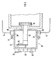
- the design of an ignition distributor 18 is shown schematically in FIG. 2.
- the horizontal distributor housing 17 installed with a horizontal axis is closed by a flange-mounted distributor cap 21.
- the ignition distributor 18 for a 6-cylinder internal combustion engine contains six Zind electrodes 22 and a center electrode 23 in the bottom of the distributor flap 21, which contacts an electrode 25 attached to the distributor shaft 24.
- the distributor shaft 24 is driven by the internal combustion engine via a gearwheel 26 and, via the rotating electrode 25, outputs the high voltage generated by the ignition coil (not shown) in the rhythm of the firing order of the cylinders via the ignition electrodes 22 to the spark plugs of the cylinders.
- the ozone that arises when the high-voltage current is interrupted by sparking is removed from the distributor housing 17 by introducing charge air.
- the line 14 is screwed to the underside 27 of the distributor housing 17 with a nut 28 and goes off at the top 29 of the distributor housing.
- the distributor housing 17 is rinsed through, the water that collects on the underside 27 is also entrained and removed from the distributor housing 17.
- the lubricating oil system consists of a supply line 30 through which lubricating oil is conveyed from a container 32 to the crankcase 33 of the internal combustion engine and distributed to its lubrication points by means of an oil pump 31, and a first return line 35 containing an oil cooler 34 from the crankcase 33 to the container 32.
- a second return line 36 leads from the cylinder head 1 via a throttle 37 and an auxiliary oil pump 38 to the tank 32.
- a pressure line 38 to the bypass valve 7 is connected to this second return line 36 before the throttle 37.
- a return line 39 leading from the bypass valve 7 opens into the first return line 35 and is controlled by a pressure regulator 40 inserted therein, which in turn is pneumatically controlled by the pressure difference prevailing at the throttle valve 41.
Landscapes
- Engineering & Computer Science (AREA)
- Chemical & Material Sciences (AREA)
- Combustion & Propulsion (AREA)
- Mechanical Engineering (AREA)
- General Engineering & Computer Science (AREA)
- Supercharger (AREA)
- Ignition Installations For Internal Combustion Engines (AREA)
Description
- Die Erfindung betrifft eine fremdgezündete Mehrzylinder-Brennkraftmaschine mit Turbolader nach dem Oberbegriff des Anspruchs 1.
- Im Zündverteiler einer Brennkraftmaschine entstehen beim Unterbrechen des Hochspannungstromes Funken, die zur Bildung von Ozon und Stickoxid führen. Das Ozon hat eine starke Oxidationswirkung und verursacht bei längerer Einwirkung Korrosionen an den elektrischen Kontakten und sonstigen Metallteilen des Zündverteilers. Auch die Alterung des Schmierfetts an den Lagerstellen des Zündverteilers wird durch Ozoneinwirkung in unerwünschter Weise beschleunigt. Man ist deshalb bestrebt, das sich bildende Ozon so rasch wie möglich aus dem Gehäuse des Zündverteilers zu entfernen. Nach DE-OS 33 22 545 geschieht das dadurch, daß auf der Verteilerwelle ein Schaufelrad befestigt ist, das Gase aus dem Zündverteiler durch Öffnungen im Verteilergehäuse hindurch an die Umgebung abführt. Während bei normalem Umgebungsdruck in Meeresniveau diese Schutzmaßnahme ausreicht, besteht bei größeren geodätischen Höhen wegen des geringeren Drucks der Umgebungsluft und der geringeren Luftdichte im Verteilergehäuse eine erhöhte Gefahr eines Funkenüberschlags und damit von Fehlzündungen in der Brennkraftmaschine.
- Es ist die Aufgabe der Erfindung, bei einer fremdgezündeten, mit einem Turbolader aufgeladenen Brennkraftmaschine, die als Antriebsaggregat für Flugzeuge in größeren Höhen besonders gut geeignet ist, eine noch wirksamere Luftdurchströmung des Zündverteilers zu ermöglichen.
- Wenn zur Lösung dieser Aufgabe am Verteilergehäuse des Zündverteilers die vom Turbolader zum Zylinderkopf führende Ladeluftleitung angeschlossen ist, liegt der Eintrittsdruck zum Verteilergehäuse schon bei Meeresniveau über dem Umgebungsdruck. Diese Druckdifferenz sorgt dafür, daß eine gute Durchströmung des Zündverteilers sichergestellt ist.
- Um einen Verlust an Ladeluft zu vermeiden, wird in einer vorteilhaften Ausgestaltung der Erfindung das Verteilergehäuse in einer Bypaßleitung zum Ladeluftkühler so angeordnet, daß die vor dem Ladeluftkühler abgezweigte Ladeluft nach Durchströmen des Verteilergehäuses wieder hinter dem Ladeluftkühler in die Ladeluftleitung einmündet. Für die Durchströmung steht die am Ladeluftkühler sich ergebende Druckdifferenz zur Verfügung. Wenn der Ladedurck unabhängig von der geodätischen Höhe konstant gehalten wird, um eine gleichbleibende Leistung der Brennkraftmaschmine bei allen Flughöhen zu gewährleisten, hat auch die Luftdichte im Verteilergehäuse einen konstant hohen Wert; Funkenüberschläge von der einen zur anderen Kontaktstelle können auf diese Weise vermieden werden.
- Ein Ausführungsbeispiel der Erfindung ist in der Zeichnung dargestellt und wird nachfolgend erläutert.
- Vom Zylinderkopf 1 einer Brennkraftmaschine führt eine Abgasleitung 2 zur Turbine 3 eines Abgasturboladers 4 und von dort nach dessen Durchströmen über einen Schalldämpfer 5 ins Freie. Parallel zur Turbine 3 liegt eine Bypaßleitung 6, in die ein Bypaßventil 7 eingesetzt ist, über das je nach seiner Stellung mehr oder weniger Abgas in den Schalldämpfer 5 gelangt, ohne die Turbine 3 zu beaufschlagen.
- Die Turbine 3 treibt einen Verdichter 8 an, mit dem Luft aus einem Luftfilter 9 angesaugt und unter Druckerhöhung in eine Ladeluftleitung 10 gefördert wird. Die Ladeluftleitung 10 führt über einen Ladeluftkühler 11 zu einem eine Einspritzanlage steuernden Luftmengenmesser 12 und von dort zum Zylinderkopf 1 der Brennkraftmaschine. Von der Ladeluftleitung 10 zweigt vor dem Ladeluftkühler 11 eine Belüftungsleitung 13 ab, die sich in strömungsmäßig parallele Leitungen 14 und 15 aufteilt und dann in einer gemeinsamen Leitung 16 weitergeführt ist. Die Leitung 16 mündet in Strömungsrichtung gesehen hinter dem Ladeluftkühler 11 in die Ladeluftleitung 10 ein und bildet zusammen mit der Belüftungsleitung 13 eine Bypaßleitung zum Ladeluftkühler 11. In die Leitung 14 ist das Verteilergehäuse 17 eines Zündverteilers 18, in die Leitung 15 das Verteilergehäuse 19 eines zweiten Zündverteilers 20 eingesetzt. Zwei Zündverteiler sind nötig, wenn, wie es für Flugmotoren vorgeschrieben ist, mit Doppelzündung gearbeitet wird.
- Die konstruktive Ausbildung eines Zündverteilers 18 ist schematisch in Fig. 2 dargestellt. Das liegend, mit horizontaler Achse eingebaute Verteilergehäuse 17 ist durch eine angeflanschte Verteilerkappe 21 verschlossen. Der Zündverteiler 18 für eine 6-Zylinder-Brennkraftmaschine enthält im Boden der Verteilerklappe 21 sechs Zindelektroden 22 und eine Mittenelektrode 23, die eine auf der Verteilerwelle 24 angebrachte Elektrode 25 kontaktiert. Die Verteilerwelle 24 ist über ein Zahnrad 26 von der Brennkraftmaschine angetrieben und gibt über die umlaufende Elektrode 25 die von der nicht dargestellten Zündspule erzeugte Hochspannung im Rythmus der Zündfolge der Zylinder über die Zündelektroden 22 auf die Zündkerzen der Zylinder. Das beim Unterbrechen des Hochspannungsstromes durch Funkenbildung entstehende Ozon wird aus dem Verteilergehäuse17 durch Einleiten von Ladeluft entfernt. Hierzu ist die Leitung 14 an die Unterseite 27 des Verteilergehäuses 17 mit einer Mutter 28 angeschraubt und geht an der Oberseite 29 des Verteilergehäuses ab. Mit dem Durchspülen des Verteilergehäuses 17 wird zugleich das sich an der Unterseite 27 ansammelnde Wasser mitgerissen und aus dem Verteilergehäuse 17 entfernt.
- Zur Steuerung des hydraulisch betätigbaren Bypaßventils 7 ist es an das Schmierölsystem der mit Trockensumpfschmierung ausgestatteten Brennkraftmaschine angeschlossen. Das Schmierölsystem besteht aus einer Zuführleitung 30, durch die mittels einer in sie eingesetzten Ölpumpe 31 Schmieröl von einem Behäler 32 zum Kurbelgehäuse 33 der Brennkraftmaschine gefördert und auf deren Schmierstellen verteilt wird, sowie aus einer einen Ölkühler 34 enthaltenden ersten Rückleitung 35 vom Kurbelgehäuse 33 zum Behälter 32. Eine zweite Rückleitung 36 führt aus dem Zylinderkopf 1 über eine Drossel 37 und eine Zusatzölpumpe 38 ebenfalls zum Behälter 32. An diese zweite Rückleitung 36 ist vor der Drossel 37 eine Druckleitung 38 zum Bypaßventil 7 angeschlossen. Eine vom Bypaßventil 7 abgehende Rückleitung 39 mündet in die erste Rückleitung 35 ein und ist durch einen in sie eingesetzten Druckregler 40 gesteuert, der seinerseits von der an der Drosselklappe 41 herrschenden Druckdifferenz pneumatisch gesteuert ist.
Claims (5)
- Fremdgezündete Mehrzylinder-Brennkraftmaschine, die mit einem Turbolader (4) aufgeladen ist, wobei die Ladeluft in einem Ladeluftkühler (11) vor Eintritt in den Zylinderkopf (1) der Brennkraftmaschine gekühlt wird und wobei ein Zündverteiler (18, 20) vorgesehen ist, dessen ihn umschließendes Verteilergehäuse (17, 19) mit Luft zwangsdurchströmt ist, dadurch gekennzeichnet, daß das Verteilergehäuse (17) an die vom Verdichter (8) des Turboladers (4) zum Zylinderkopf (1) führende Ladeluftleitung (10) angeschlossen ist und von Ladeluft durchströmt ist.
- Brennkraftmaschine nach Anspruch 1, dadurch gekennzeichnet, daß das Verteilergehäuse (17) in eine Bypaßleitung (13, 16) eingesetzt ist, die an der Ladeluftleitung (10) vor dem Ladeluftkühler (11) abzweigt und hinter ihm in die Ladeluftleitung (10) einmündet.
- Brennkraftmaschine nach Anspruch 2, dadurch gekennzeichnet, daß in die Bypaßleitung (13, 16) zwei Verteilergehäuse (17, 19) eingesetzt sind, die zueinander parallel geschaltet von Ladeluft durchströmt sind.
- Brennkraftmaschine nach Anspruch 1, dadurch gekennzeichnet, daß der Druck der Ladeluft unabhängig von der geodätischen Höhe, in der sich die Brennkraftmaschine befindet, konstant gehalten wird.
- Brennkraftmaschine nach Anspruch 4, dadurch gekennzeichnet, daß ein Bypaßventil (7), das in eine die Turbine (3) des Turboladers (4) umgehende Bypaßleitung (6) eingesetzt ist, mit zunehmender geodätischer Höhe entsprechend geschlossen wird.
Applications Claiming Priority (2)
| Application Number | Priority Date | Filing Date | Title |
|---|---|---|---|
| DE19873715062 DE3715062A1 (de) | 1987-05-06 | 1987-05-06 | Fremdgezuendete mehrzylinder-brennkraftmaschine mit turbolader |
| DE3715062 | 1987-05-06 |
Publications (3)
| Publication Number | Publication Date |
|---|---|
| EP0289701A2 EP0289701A2 (de) | 1988-11-09 |
| EP0289701A3 EP0289701A3 (en) | 1989-06-14 |
| EP0289701B1 true EP0289701B1 (de) | 1992-08-12 |
Family
ID=6326945
Family Applications (1)
| Application Number | Title | Priority Date | Filing Date |
|---|---|---|---|
| EP88101458A Expired - Lifetime EP0289701B1 (de) | 1987-05-06 | 1988-02-02 | Fremdgezündete Mehrzylinder-Brennkraftmaschine mit Turbolader |
Country Status (3)
| Country | Link |
|---|---|
| US (1) | US4841926A (de) |
| EP (1) | EP0289701B1 (de) |
| DE (2) | DE3715062A1 (de) |
Families Citing this family (3)
| Publication number | Priority date | Publication date | Assignee | Title |
|---|---|---|---|---|
| KR900002242A (ko) * | 1988-07-14 | 1990-02-28 | 나가이 아쯔시 | 자기디스크 카트리지 |
| WO2008094225A1 (en) * | 2007-02-02 | 2008-08-07 | Earle Schaller | Improved density current baffle for a clarifier tank |
| US8857552B2 (en) * | 2011-04-01 | 2014-10-14 | Jeffrey David Oltmans | Turbocharger for motorcycle |
Family Cites Families (16)
| Publication number | Priority date | Publication date | Assignee | Title |
|---|---|---|---|---|
| US2195825A (en) * | 1937-05-11 | 1940-04-02 | Universal Engine And Propeller | Fuel system for engines |
| US2257781A (en) * | 1938-10-27 | 1941-10-07 | Bendix Aviat Corp | Distributor |
| US2207368A (en) * | 1939-05-17 | 1940-07-09 | Gen Motors Corp | Ignition distributor |
| US2323792A (en) * | 1940-05-17 | 1943-07-06 | Shell Dev | Spark plug |
| US2310575A (en) * | 1940-05-17 | 1943-02-09 | Shell Dev | Ignition system for internal combustion engines |
| US2798109A (en) * | 1954-05-25 | 1957-07-02 | Robert H Voigt | Dehumidifier for an automotive distributor |
| JPS55144855U (de) * | 1979-04-03 | 1980-10-17 | ||
| JPS566955U (de) * | 1979-06-27 | 1981-01-21 | ||
| DE7924892U1 (de) * | 1979-09-01 | 1981-03-12 | Robert Bosch Gmbh, 7000 Stuttgart | Hochspannungsverteiler für eine Zündanlage von Brennkraftmaschinen |
| US4302638A (en) * | 1979-12-14 | 1981-11-24 | Ford Motor Company | Venting system for an internal combustion engine ignition distributor |
| GB2095328B (en) * | 1981-02-06 | 1984-08-30 | Honda Motor Co Ltd | Controlling supercharged ic engine intake systems |
| US4445493A (en) * | 1981-12-03 | 1984-05-01 | Ford Motor Company | Distributor with reduced radio frequency interference |
| US4505340A (en) * | 1982-06-03 | 1985-03-19 | Yantsen Ivan A | Hydropneumatic percussive tool |
| US4666383A (en) * | 1982-08-26 | 1987-05-19 | Mendler Edward Charles Iii | Rotary machine |
| US4512296A (en) * | 1984-06-04 | 1985-04-23 | Herrington Allen G | Distributor moisture guard |
| JPS62243969A (ja) * | 1986-04-15 | 1987-10-24 | Honda Motor Co Ltd | デイストリビユ−タ |
-
1987
- 1987-05-06 DE DE19873715062 patent/DE3715062A1/de not_active Withdrawn
- 1987-05-06 US US07/191,125 patent/US4841926A/en not_active Expired - Fee Related
-
1988
- 1988-02-02 EP EP88101458A patent/EP0289701B1/de not_active Expired - Lifetime
- 1988-02-02 DE DE8888101458T patent/DE3873595D1/de not_active Expired - Lifetime
Also Published As
| Publication number | Publication date |
|---|---|
| EP0289701A2 (de) | 1988-11-09 |
| US4841926A (en) | 1989-06-27 |
| EP0289701A3 (en) | 1989-06-14 |
| DE3715062A1 (de) | 1988-11-17 |
| DE3873595D1 (de) | 1992-09-17 |
Similar Documents
| Publication | Publication Date | Title |
|---|---|---|
| EP1065350A2 (de) | Brennkraftmaschine mit einer Entlüftungseinrichtung | |
| DE2949790A1 (de) | Frischgasleitungssystem fuer kolbenverbrennungsmotoren | |
| DE3439738C2 (de) | Aufgeladene Brennkraftmaschine | |
| EP0158008A2 (de) | Luftansauganlage einer Mehrzylinder-Brennkraftmaschine | |
| DE2632015A1 (de) | Dieselbrennkraftmaschine | |
| EP2256314A1 (de) | Verbrennungsmotor | |
| EP0790393B1 (de) | Brennkraftmaschine mit Sauganlage mit einem an gegenüberliegenden Zylinderbänken anschliessbaren Sammler, insbesondere V 8-Motor | |
| EP0289701B1 (de) | Fremdgezündete Mehrzylinder-Brennkraftmaschine mit Turbolader | |
| DE2446490A1 (de) | Aufgeladene kolbenbrennkraftmaschine | |
| DE3133953A1 (de) | Verbrennungskraftmaschine | |
| DE3929124C2 (de) | Brennkraftmaschine mit einem Aufladeaggregat | |
| DE4042415A1 (de) | Verbrennungsmotor mit in v-form angeordneten zylinderbaenken | |
| DE102019202342B4 (de) | Brennkraftmaschine und Kraftfahrzeug | |
| DE4238179C2 (de) | Brennkraftmaschine mit einer Zündkerze zum Zünden von Kraftstoff-Luft-Gemischen | |
| DE3421355A1 (de) | Verfahren zum betrieb einer brennkraftmaschine mit abgasturbolader und vorrichtung zur durchfuehrung des verfahrens | |
| DE2603969C2 (de) | Luftgekühlte Hubkolbenbrennkraftmaschine | |
| DE871983C (de) | Verfahren zum Betrieb von aufgeladenen Zweitakt-Verbrennungsmotoren mit durch Abgasturbine angetriebenem Spuel- und Ladegeblaese | |
| DE2445474A1 (de) | Aufgeladene dieselbrennkraftmaschine mit zweistufiger aufladung | |
| DE917757C (de) | Zweitakt-Brennkraftmaschine mit Reihenanordnung der Zylinder | |
| DE913484C (de) | V-foermige Zweitakt-Brennkraftmaschine mit einem Abgasturbogeblaese und einem mechanisch angetriebenen Spuelgeblaese | |
| DE102010009913A1 (de) | Verbrennungskraftmaschine | |
| EP0125407B1 (de) | Mittels Abgasturbolader nach dem Stauprinzip aufgeladene Viertakt-Brennkraftmaschine | |
| DE973152C (de) | Fluessigkeitsgekuehlte Zweitakt-Brennkraftmaschine | |
| DE959599C (de) | Zweitakt-Einspritzbrennkraftmaschine | |
| DE475463C (de) | Verfahren zum Ausblasen der Tauchtanks bei Unterseebooten |
Legal Events
| Date | Code | Title | Description |
|---|---|---|---|
| PUAI | Public reference made under article 153(3) epc to a published international application that has entered the european phase |
Free format text: ORIGINAL CODE: 0009012 |
|
| AK | Designated contracting states |
Kind code of ref document: A2 Designated state(s): DE FR GB IT |
|
| PUAL | Search report despatched |
Free format text: ORIGINAL CODE: 0009013 |
|
| AK | Designated contracting states |
Kind code of ref document: A3 Designated state(s): DE FR GB IT |
|
| 17P | Request for examination filed |
Effective date: 19891017 |
|
| 17Q | First examination report despatched |
Effective date: 19911213 |
|
| ITF | It: translation for a ep patent filed | ||
| GRAA | (expected) grant |
Free format text: ORIGINAL CODE: 0009210 |
|
| AK | Designated contracting states |
Kind code of ref document: B1 Designated state(s): DE FR GB IT |
|
| REF | Corresponds to: |
Ref document number: 3873595 Country of ref document: DE Date of ref document: 19920917 |
|
| GBT | Gb: translation of ep patent filed (gb section 77(6)(a)/1977) | ||
| ET | Fr: translation filed | ||
| PGFP | Annual fee paid to national office [announced via postgrant information from national office to epo] |
Ref country code: GB Payment date: 19930215 Year of fee payment: 6 |
|
| PGFP | Annual fee paid to national office [announced via postgrant information from national office to epo] |
Ref country code: FR Payment date: 19930226 Year of fee payment: 6 |
|
| PGFP | Annual fee paid to national office [announced via postgrant information from national office to epo] |
Ref country code: DE Payment date: 19930309 Year of fee payment: 6 |
|
| PLBE | No opposition filed within time limit |
Free format text: ORIGINAL CODE: 0009261 |
|
| STAA | Information on the status of an ep patent application or granted ep patent |
Free format text: STATUS: NO OPPOSITION FILED WITHIN TIME LIMIT |
|
| 26N | No opposition filed | ||
| PG25 | Lapsed in a contracting state [announced via postgrant information from national office to epo] |
Ref country code: GB Effective date: 19940202 |
|
| GBPC | Gb: european patent ceased through non-payment of renewal fee |
Effective date: 19940202 |
|
| PG25 | Lapsed in a contracting state [announced via postgrant information from national office to epo] |
Ref country code: FR Effective date: 19941031 |
|
| PG25 | Lapsed in a contracting state [announced via postgrant information from national office to epo] |
Ref country code: DE Effective date: 19941101 |
|
| REG | Reference to a national code |
Ref country code: FR Ref legal event code: ST |
|
| PG25 | Lapsed in a contracting state [announced via postgrant information from national office to epo] |
Ref country code: IT Free format text: LAPSE BECAUSE OF NON-PAYMENT OF DUE FEES;WARNING: LAPSES OF ITALIAN PATENTS WITH EFFECTIVE DATE BEFORE 2007 MAY HAVE OCCURRED AT ANY TIME BEFORE 2007. THE CORRECT EFFECTIVE DATE MAY BE DIFFERENT FROM THE ONE RECORDED. Effective date: 20050202 |