EP0289946A2 - Gerät zum Verteilen von Flüssigkeitsproben - Google Patents
Gerät zum Verteilen von Flüssigkeitsproben Download PDFInfo
- Publication number
- EP0289946A2 EP0289946A2 EP88106887A EP88106887A EP0289946A2 EP 0289946 A2 EP0289946 A2 EP 0289946A2 EP 88106887 A EP88106887 A EP 88106887A EP 88106887 A EP88106887 A EP 88106887A EP 0289946 A2 EP0289946 A2 EP 0289946A2
- Authority
- EP
- European Patent Office
- Prior art keywords
- tips
- distribution
- air
- test tubes
- sample
- Prior art date
- Legal status (The legal status is an assumption and is not a legal conclusion. Google has not performed a legal analysis and makes no representation as to the accuracy of the status listed.)
- Granted
Links
Images


Classifications
-
- A—HUMAN NECESSITIES
- A61—MEDICAL OR VETERINARY SCIENCE; HYGIENE
- A61B—DIAGNOSIS; SURGERY; IDENTIFICATION
- A61B5/00—Measuring for diagnostic purposes; Identification of persons
- A61B5/14—Devices for taking samples of blood ; Measuring characteristics of blood in vivo, e.g. gas concentration within the blood, pH-value of blood
-
- G—PHYSICS
- G01—MEASURING; TESTING
- G01N—INVESTIGATING OR ANALYSING MATERIALS BY DETERMINING THEIR CHEMICAL OR PHYSICAL PROPERTIES
- G01N35/00—Automatic analysis not limited to methods or materials provided for in any single one of groups G01N1/00 - G01N33/00; Handling materials therefor
- G01N35/10—Devices for transferring samples or any liquids to, in, or from, the analysis apparatus, e.g. suction devices, injection devices
- G01N35/1065—Multiple transfer devices
- G01N35/1067—Multiple transfer devices for transfer to or from containers having different spacing
-
- A—HUMAN NECESSITIES
- A61—MEDICAL OR VETERINARY SCIENCE; HYGIENE
- A61B—DIAGNOSIS; SURGERY; IDENTIFICATION
- A61B5/00—Measuring for diagnostic purposes; Identification of persons
- A61B5/145—Measuring characteristics of blood in vivo, e.g. gas concentration or pH-value ; Measuring characteristics of body fluids or tissues, e.g. interstitial fluid or cerebral tissue
- A61B5/1468—Measuring characteristics of blood in vivo, e.g. gas concentration or pH-value ; Measuring characteristics of body fluids or tissues, e.g. interstitial fluid or cerebral tissue using chemical or electrochemical methods, e.g. by polarographic means
-
- G—PHYSICS
- G01—MEASURING; TESTING
- G01N—INVESTIGATING OR ANALYSING MATERIALS BY DETERMINING THEIR CHEMICAL OR PHYSICAL PROPERTIES
- G01N35/00—Automatic analysis not limited to methods or materials provided for in any single one of groups G01N1/00 - G01N33/00; Handling materials therefor
- G01N35/10—Devices for transferring samples or any liquids to, in, or from, the analysis apparatus, e.g. suction devices, injection devices
- G01N35/1009—Characterised by arrangements for controlling the aspiration or dispense of liquids
- G01N35/1016—Control of the volume dispensed or introduced
- G01N2035/1018—Detecting inhomogeneities, e.g. foam, bubbles, clots
-
- G—PHYSICS
- G01—MEASURING; TESTING
- G01N—INVESTIGATING OR ANALYSING MATERIALS BY DETERMINING THEIR CHEMICAL OR PHYSICAL PROPERTIES
- G01N35/00—Automatic analysis not limited to methods or materials provided for in any single one of groups G01N1/00 - G01N33/00; Handling materials therefor
- G01N35/10—Devices for transferring samples or any liquids to, in, or from, the analysis apparatus, e.g. suction devices, injection devices
- G01N35/1009—Characterised by arrangements for controlling the aspiration or dispense of liquids
- G01N2035/1025—Fluid level sensing
-
- G—PHYSICS
- G01—MEASURING; TESTING
- G01N—INVESTIGATING OR ANALYSING MATERIALS BY DETERMINING THEIR CHEMICAL OR PHYSICAL PROPERTIES
- G01N35/00—Automatic analysis not limited to methods or materials provided for in any single one of groups G01N1/00 - G01N33/00; Handling materials therefor
- G01N35/10—Devices for transferring samples or any liquids to, in, or from, the analysis apparatus, e.g. suction devices, injection devices
- G01N2035/1027—General features of the devices
- G01N2035/103—General features of the devices using disposable tips
-
- G—PHYSICS
- G01—MEASURING; TESTING
- G01N—INVESTIGATING OR ANALYSING MATERIALS BY DETERMINING THEIR CHEMICAL OR PHYSICAL PROPERTIES
- G01N35/00—Automatic analysis not limited to methods or materials provided for in any single one of groups G01N1/00 - G01N33/00; Handling materials therefor
- G01N35/10—Devices for transferring samples or any liquids to, in, or from, the analysis apparatus, e.g. suction devices, injection devices
- G01N35/1065—Multiple transfer devices
- G01N35/1067—Multiple transfer devices for transfer to or from containers having different spacing
- G01N2035/1069—Multiple transfer devices for transfer to or from containers having different spacing by adjusting the spacing between multiple probes of a single transferring head
Definitions
- the present invention relates to an apparatus for distributing sample liquid, such as sampled blood, from a test tube into a plurality of other tubes, so that the distributed portions of the sample liquid are subjected to different items of analysis.
- sample liquid such as blood
- Analyzers have been developed, and greatly improved analyzers have been put to practical use.
- the blood analyzer is a good example. Nonetheless, the distribution of a liquid sample is performed solely by human labor, as is seen in the hospitals and the research institutes. No automatic apparatuses for distributing a sample liquid into a plurality of test tubes or the like have not been developed.
- the sample liquid may spill, wetting the hands of the persons engaged in the distribution of the liquid, or staining the floor.
- the test tube from which the sample liquid is being distributed, or the test tubes into which the liquid is being distributed may be dropped, by mistake, onto the floor, inevitably staining the floor.
- the sample-distribution by means of manual labor requires a long time and is error-prone. Because of these problems, it is difficult to keep the sample-distribution room sufficiently clean and sanitary, or to accomplish a sufficiently high work efficiency.
- the inventors hereof studied the possibility of developing an apparatus which has distribution tips, vacuum means for supplying a sample liquid into the tips from a test tube, transport means for moving the tips containing the liquid to other test tubes, and sample-distributing means for distributing the portions of the sample liquid from the tips into the test tubes. They found that such an apparatus cannot be practically employed unless it satisfies the following requirements:
- the second object of the invention is to provide an apparatus which can automatically distribute a sample liquid from distribution tips into test tubes, and can quickly arrange the distribution tips at the same intervals as the test tubes are held in a rack.
- the third object of this invention is to provide an apparatus which can automatically distribute a sample liquid from distribution tips into test tubes, and can prevent the sample liquid from dribbling from the tips into the test tubes other than the destination ones while the tips are being moved from the source tubes to the destination tubes, due to the vibration or the like applied to the tips during the transportation.
- the fourth object of the present invention is to provide an apparatus which can automatically distribute a sample liquid from distribution tips into test tubes, and can automatically replace the distribution tips with new and clean ones, quickly and smoothly.
- an apparatus comprising distribution tips, vacuum means for supplying a sample liquid from a source test tube into the distribution tips, transport means for moving the tips containing the sample liquid to destination tubes, and sample-distributing means for distributing the portions of the sample liquid from the tips into the destination tubes.
- the distribution tips are connected to air pipes.
- the air pipes are connected to changeover valves, respectively.
- Each changeover valve has two air-inlet ports.
- the first air-inlet port is connected to a pressure detector, which in turn is coupled to an air supply device.
- the second air-inlet port is connected to an air cylinder containing a piston.
- the pressure detector generates an electric signal upon detecting a change in the pressure of the air being supplied from the air supply device, and supplies this signal to the changeover valve.
- the valve connects the air pipe to the air supply device or the air cylinder.
- the sample liquid can be sucked from the source tube into distribution tip by moving the piston in a first direction, or supplied from the tip into the destination tube by moving the piston in a second direction opposite to the first direction.
- the air supply device is started, air is supplied from the distribution tip at a low rate.
- the tip is gradually lowered into the source tube.
- the air pressure of the air being supplied from the air supply device changes, whereby the pressure detector generates a signal.
- the changeover valve connects the air pipe to the air cylinder.
- the piston of the air cylinder is moved in the first direction, whereby a portion of the liquid is sucked up into the distributing tip and retained therein.
- the distribution tip is moved from the source tube to the destination tube.
- the piston is moved in the second direction, whereby the liquid is distributed from the tip into the destination tube.
- an apparatus which comprises distribution tips, vacuum means for supplying a sample liquid from a source test tube into the distribution tips, transport means for moving the tips containing the sample liquid to destination tubes, and sample-distributing means for distributing the portions of the sample liquid from the tips into the destination tubes.
- the apparatus further comprises a sample-distributing section having distribution units.
- Each distribution units has a tip holder for holding the distribution tip. Pins protrude from the tip holders holding the distribution tips, or from the members supporting the tip holders.
- the tip holders are set apart at regular intervals, and the pins are, thus, set apart at regular intervals, too.
- These pins are inserted in the slit cut in a slanting lever.
- the lever is fixed at one end and can be rotated by drive means such as a pulse motor.
- the intervals among the pins are set apart is changed.
- the regular intervals among the distribution tips is also changed.
- the distribution tips can be set at the same regular intervals as the destination test tubes, whereby portions of the sample liquid are simultaneously distributed into these test tubes.
- an apparatus which comprises distribution tips, vacuum means for supplying a sample liquid from a source test tube into the distribution tips, transport means for moving the tips containing the sample liquid to destination tubes, and sample-distributing means for distributing the portions of the sample liquid from the tips into the destination tubes.
- the apparatus further comprises a sample-distributing section having distribution units and a plurality of cups.
- Each distribution unit has a tip holder for holding the distribution tip.
- the cups are positioned below distribution tips held by the holders, while the tips are being moved from the source tubes to the destination tubes, and vice versa, and are moved by drive means and remain away from the tips while the sample liquid is being sucked up into, or supplied from, the distribution tips.
- the liquid if dribbling from the tips during the transport of the tips, falls into the cups, not into the test tubes other than the destination tubes.
- an apparatus which comprises distribution tips, vacuum means for supplying a sample liquid from a source test tube into the distribution tips, transport means for moving the tips containing the liquid to destination tubes, and sample-distributing means for distributing the portions of the sample liquid from the tips into the destination tubes.
- the apparatus further comprises a jig and a sample-distributing section having distribution units.
- Each distribution unit has a tip holder and a plug attached to the holder.
- the plug has an O-ring mounted on it, and can be removably fitted in the proximal end of the distribution tip held by the holder.
- the jig is a rectangular plate having a semicircular notches cut in one side.
- the notches have such a radius that the plugs can be inserted into them, but the proximal ends of the tips cannot be inserted into them.
- the jig can be moved relative to the distribution tips, in both the vertical direction and the horizontal direction. In operation, when the jig or the tips are moved vertically and horizontally, the distribution tips are easily attached to, for detached from, the distribution units.
- Figs. 1 and 2 show an apparatus according to the present invention, which can automatically distribute a sample liquid from a source test tube into a plurality of destination test tubes.
- the apparatus comprises housing 1, movable bed 2 mounted on housing 1, a sample-distributing section attached to bed 2 and including five distribution tips 3, L-shaped post 4 having a vertical portion protruding upward from housing 1 and a horizontal portion extending from the vertical portion, and console panel 5 attached to the free end of L-shaped post 4.
- Housing 1 contains a control system including a sequencer.
- Bed 2 can be moved in the direction of arrow X and also in the direction of arrow Y, as is illustrated in Figs. 1 and 2.
- the apparatus further comprises a sample-distribution section having five identical distribution units.
- Fig. 3 schematically shows the sample-distributing section.
- a sample blood is contained in source test tube 10, with serum 12 separated from cells 13 by separation agent 11.
- Each distribution tip 3 can be moved up and down by a drive mechanism (not shown), so that its distal end can be inserted into source tube 10.
- the proximal end of tip 3 is coupled to one end of air pipe 20 in airtight fashion.
- the other end of pipe 20 is connected to changeover valve 21 having two air-inlet ports 21a and 21b.
- First port 21a is connected by pipe 22 to air supply device 23 comprising compressed air source 23a and pressure regulator 23b.
- Second port 21b is connected by pipe 25 to air cylinder 26 having a piston.
- Pressure detector 24 is coupled to pipe 22, for detecting changes in the pressure of the air flowing through pipe 22. Upon detecting a change in the air pressure, detector 24 generates and supplies a signal to changeover valve 21. In response to this signal, valve 21 connects pipe 20 to pipe 25. As long valve 21 connects pipes 20 and 25, serum 10 can be sucked from tube 10 into tip 3 and remained therein when the piston is moved in the direction of arrow A, and can be distributed from tip 10 into a destination test tube (not shown) when the piston is moved in the direction of arrow B.
- Pressure switch 27 is connected to pipe 20, for checking tip 3 for an abnormal condition, such as clogging.
- air supply device 23 is turned on, whereby air is supplied at a low rate to tip 3 through pressure detector 24, and changeover valve 21. Hence, the air is continuously supplied from distribution tip 3 through the distal end thereof. In this condition, tip 3 is gradually lowered into source tube 10. The moment the distal end of tip 3 reaches serum 12, the air stream receives a resistance, and the pressure of air flowing through pipes 20 and 22 rises. Pressure detector 24 detects this pressure rise, and generates and supplies a signal to changeover valve 21. In response to this signal, valve 21 disconnects pipe 20 from first port 21a and connects pipe 20 to second port 21b, thus connecting pipe 20 to pipe 25.
- the amount of serum 12 contained in source tube 10 has been calculated based on the surface level of separation agent 11, the surface level of serum 12, and the inner diameter of tube 10. Distribution tip 3 is lowered in accordance with the calculated amount of serum 12, so as to prevent its distal end from reaching separation agent 11.
- movable bed 2 is moved toward the place where destination test tubes are located, until distribution tips 3 are positioned right above the destination tubes, respectively. Then, each tip 3 is lowered until its distal end enters the destination tube.
- the piston of air cylinder 26 is moved in the direction of arrow B, whereby serum 12 is supplied from tip 3 into the destination tube.
- serum 12 is distributed from source tube 10 into the destination tube.
- tip 3 is replaced with a new one, so that another sample liquid is distributed from a source test tube into a destination test tube.
- the serum can be distributed from tip 3 into a plurality of test tubes.
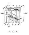
- Fig. 4 is a perspective view of the sample-distributing section, as is viewed from the back.
- the section comprises two vertical plates 30a and 30b located in a face-to-face relation, and five distribution units 31 to 35 interposed between plates 30a and 30b.
- units 31 and 35 are fastened to plates 30a and 30b, respectively.
- the remaining units 32, 33, and 34 can slide on guide rails (not shown) which extend between plates 30a and 30b.
- Distribution units 31 to 35 have distribution tip 3 (not shown) each.
- Unit 31 is fastened to plate 30a, and unit 35 is secured to plate 30b.
- Rectangular plates 41 to 44 are fastened to the backs of units 31 to 34, respectively.
- These plates 41 to 44 extend horizontally and parallel to one another, and are staggered in the vertical direction. They have pins 51 to 55 protruding from their free ends. Pins 51 to 54 are arranged in a line inclined to the direction in which units 32, 34, and 34 can slide on the rails. Pins 51 to 54 are inserted in slit 61 cut in lever 60. Lever 60 is supported, at one end, by pivot 62 protruding from the back of distribution unit 35, and can thus rotate around pivot 62.
- the sample-distributing section further comprises motor support 70 extending horizontally from the upper end of plate 30b toward plate 30a and having a rectangular portion projecting upward from the free end.
- Pulse motor 71 is fixed on support 70.
- Shaft 72 of pulse motor 71 is fastened to threaded rod 73 is fastened to shaft 72 of pulse motor 71.
- Rod 73 extends through the hole cut in the rectangular portion of support 70 and set in screw engagement with the screw hole cut in the upper end portion of plate 30a.
- the sample-distributing section 30 can be used to distribute from source test tubes held in the holes of a rack, which are arranged at whatever intervals, into destination test tubes held in the holes of a rack, which are arranged at whatever intervals.
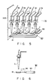
- Fig. 5 is a perspective view of distributing section 30, as is viewed from the front.
- Fig. 6 is a side view of one of the distribution units included in the section 30. As is evident from Figs. 5 and 6, each of distribution units 31 to 35 has distribution tip 3.
- Section 30 is attached to movable bed 2, and can move in the directions of arrows X and Y (Figs. 1 and 2), along with movable bed 2.
- Sample-distributing section 30 has tray mechanism 80 comprising tray 81, two paralleled rods 82, and drive cylinder 83. Rods 82 connect tray 81 to drive cylinder 83.
- Fig. 7 is a perspective view of mechanism 90 for attaching distributing tips to, and detaching them from, the distributing units of sample-distributing section 30.
- This mechanism 90 comprises support plates 91 (only one shown), boxes 92 (only one shown) fastened to plates 91, and plugs 93 (only one shown) suspended from boxes 92.
- Air pipes 20 are connected to the upper ends of boxes 92.
- Plugs 93 are made of, for example, hard rubber and shaped such that they can be inserted into the proximal ends of tips 3. They have through holes and connected by air pipes to boxes 92. The through holes of plugs 93 thus communicate with air pipes 20.
- Coil spring 94 is interposed between each box 92 and each plug 93, and mounted on the pipe connecting the plug to the box.
- O-ring 95 is mounted on the outer periphery of each plug 93, for accomplishing a sufficiently airtight connection between plug 93 and tip 3.
- Mechanism 90 further comprises jig 100 fastened to housing 1.
- Jig 100 is a rectangular plate having five semicircular cut-outs 101 to 105 made in one longer side. Cut-outs 101 to 105 have such a radius that plugs 93 can be inserted into them, but the proximal ends of tips 3 cannot be inserted into them.
- Jig 100 can be moved relative to the distribution tips, in both the vertical direction and the horizontal direction, by means of a drive mechanism (not shown).
- Mechanism 90 operates in the following manner to attach tips 3 to, and detach them from, the distributing units of sample-distributing section 30.
- the drive mechanism (not shown) is operated, thus moving sample-distributing section 30 such that plugs 93 are placed above tips 3 held in a rack (not shown).
- the drive mechanism is operated, lowering section 30 this time, so that plugs 93 are inserted into the proximal ends of tips 3. Since coil springs 94 exert a constant force on plugs 93, plugs 93 are inserted into the proximal ends of tips smoothly and stably.
- O-rings 95 mounted on plugs 93 are in complete contact with the inner peripheries of tips 3, a sufficiently airtight connection between tips 3, on the one hand, and plugs 39, on the other, is accomplished.
- the drive mechanism (not shown) then moves section 30 upward, thus lifting tips 3, now coupled to units 31 to 35, from the rack.
- the drive mechanism is operated, thus moving section 30 such that tips 3 are moved in the direction of the arrow indicated by the one-dot, one-dash line.
- the present invention is not limited to the embodiment described above. It can also apply to apparatuses for automatically distributing sample liquids other than serum.
Landscapes
- Health & Medical Sciences (AREA)
- Life Sciences & Earth Sciences (AREA)
- Physics & Mathematics (AREA)
- General Health & Medical Sciences (AREA)
- Pathology (AREA)
- Chemical & Material Sciences (AREA)
- Engineering & Computer Science (AREA)
- Medical Informatics (AREA)
- Immunology (AREA)
- Biochemistry (AREA)
- Veterinary Medicine (AREA)
- Biophysics (AREA)
- Analytical Chemistry (AREA)
- Biomedical Technology (AREA)
- Heart & Thoracic Surgery (AREA)
- General Physics & Mathematics (AREA)
- Molecular Biology (AREA)
- Surgery (AREA)
- Animal Behavior & Ethology (AREA)
- Public Health (AREA)
- Hematology (AREA)
- Chemical Kinetics & Catalysis (AREA)
- General Chemical & Material Sciences (AREA)
- Optics & Photonics (AREA)
- Automatic Analysis And Handling Materials Therefor (AREA)
- Sampling And Sample Adjustment (AREA)
Priority Applications (1)
| Application Number | Priority Date | Filing Date | Title |
|---|---|---|---|
| AT88106887T ATE101923T1 (de) | 1987-05-02 | 1988-04-29 | Geraet zum verteilen von fluessigkeitsproben. |
Applications Claiming Priority (8)
| Application Number | Priority Date | Filing Date | Title |
|---|---|---|---|
| JP67021/87 | 1987-03-20 | ||
| JP6702287U JPS63175863U (de) | 1987-05-02 | 1987-05-02 | |
| JP6702487U JPS63175865U (de) | 1987-05-02 | 1987-05-02 | |
| JP1987067021U JPH0434456Y2 (de) | 1987-05-02 | 1987-05-02 | |
| JP67024/87 | 1987-05-02 | ||
| JP6702387U JPS63175864U (de) | 1987-05-02 | 1987-05-02 | |
| JP67023/87 | 1987-05-02 | ||
| JP67022/87 | 1987-05-02 |
Publications (3)
| Publication Number | Publication Date |
|---|---|
| EP0289946A2 true EP0289946A2 (de) | 1988-11-09 |
| EP0289946A3 EP0289946A3 (en) | 1989-08-09 |
| EP0289946B1 EP0289946B1 (de) | 1994-02-23 |
Family
ID=27464799
Family Applications (1)
| Application Number | Title | Priority Date | Filing Date |
|---|---|---|---|
| EP88106887A Expired - Lifetime EP0289946B1 (de) | 1987-05-02 | 1988-04-29 | Gerät zum Verteilen von Flüssigkeitsproben |
Country Status (9)
| Country | Link |
|---|---|
| US (1) | US5013529A (de) |
| EP (1) | EP0289946B1 (de) |
| KR (1) | KR900008959B1 (de) |
| CA (1) | CA1321940C (de) |
| DE (1) | DE3887921T2 (de) |
| DK (1) | DK170433B1 (de) |
| FI (1) | FI94288C (de) |
| GB (1) | GB2205400B (de) |
| PT (1) | PT87385A (de) |
Cited By (9)
| Publication number | Priority date | Publication date | Assignee | Title |
|---|---|---|---|---|
| DE4011584A1 (de) * | 1989-04-12 | 1990-10-18 | Olympus Optical Co | Automatisches chemisches analysiergeraet |
| US5358641A (en) * | 1989-10-27 | 1994-10-25 | Helena Laboratories Corporation | Column analyzer system and improved chromatograph column for use in the system |
| WO1997014040A1 (fr) * | 1995-10-12 | 1997-04-17 | Genomic (S.A.) | Dispositif pour le transfert d'echantillons de micro-quantites de liquides |
| EP0981048A3 (de) * | 1998-07-10 | 2000-03-08 | Bayer Corporation | Blutgerinnsel-Detektor |
| US6456944B1 (en) * | 1998-09-30 | 2002-09-24 | Roche Diagnostics Corporation | Automatic analyzer for monitoring pipetting operations |
| US6506611B2 (en) | 1998-08-07 | 2003-01-14 | Deutsches Resourcenzentrum Fur Genomforschung Gmbh | Metering head for parallel processing of a plurality of fluid samples |
| WO2006075201A1 (en) * | 2004-09-08 | 2006-07-20 | Pfizer Products Inc. | Automated system for handling and weighing analytic quantities of particulate substances |
| EP1557222A3 (de) * | 2004-01-21 | 2007-05-09 | Eppendorf Ag | Pipettiervorrichtung mit einer Abwurfeinrichtung für Pipettenspitzen |
| DE102013220427A1 (de) * | 2013-10-10 | 2015-04-16 | Hamilton Bonaduz Ag | Bewegungsvorrichtung mit kombiniertem Individual- und Blockbewegungsantrieb für mehrere gemeinsam geführte Bewegungseinheiten |
Families Citing this family (52)
| Publication number | Priority date | Publication date | Assignee | Title |
|---|---|---|---|---|
| US5045286A (en) * | 1988-02-25 | 1991-09-03 | Olympus Optical Co., Ltd. | Device for aspirating a fixed quantity of liquid |
| US5061449A (en) * | 1989-07-25 | 1991-10-29 | Matrix Technologies, Corp. | Expandable multi-channel pipetter |
| US5463895A (en) * | 1990-11-09 | 1995-11-07 | Abbott Laboratories | Sample pipetting method |
| US5380486A (en) * | 1991-04-19 | 1995-01-10 | Olympus Optical Co., Ltd. | Apparatus for taking liquid content for use in analysis out of container |
| US5525298A (en) * | 1991-04-19 | 1996-06-11 | Olympus Optical Co., Ltd. | Apparatus for taking liquid content for use in analysis out of container |
| US5312757A (en) * | 1991-05-02 | 1994-05-17 | Olympus Optical Co., Ltd. | Sample distributing method |
| US5456880A (en) * | 1992-11-20 | 1995-10-10 | Shimadzu Corporation | Micropipet apparatus and micromanipulator |
| JP3318629B2 (ja) | 1993-06-18 | 2002-08-26 | ソニー株式会社 | 液体の吸引/排出装置及び方法 |
| EP0705424A4 (de) * | 1993-06-21 | 1996-12-04 | Boehringer Mannheim Corp | Vorrichtung zum betrieb einer pipette und verfahren zur verwendung derselben |
| DE4331997A1 (de) * | 1993-09-21 | 1995-03-23 | Boehringer Mannheim Gmbh | Verfahren und System zur Mischung von Flüssigkeiten |
| JP3351615B2 (ja) * | 1994-03-17 | 2002-12-03 | ソニー株式会社 | 液の境界検出方法と液分離方法 |
| JP3115501B2 (ja) * | 1994-06-15 | 2000-12-11 | プレシジョン・システム・サイエンス株式会社 | 分注機を利用した磁性体の脱着制御方法及びこの方法によって処理される各種装置 |
| DE4423878A1 (de) * | 1994-07-07 | 1996-01-11 | Boehringer Mannheim Gmbh | Vorrichtung und Verfahren zum Abscheiden von magnetischen Mikropartikeln |
| US5639425A (en) * | 1994-09-21 | 1997-06-17 | Hitachi, Ltd. | Analyzing apparatus having pipetting device |
| DE19549559C2 (de) * | 1994-09-21 | 2000-10-12 | Hitachi Ltd | Gerät zum Analysieren des menschlichen Blutes oder Urins |
| US5750881A (en) * | 1995-07-13 | 1998-05-12 | Chiron Diagnostics Corporation | Method and apparatus for aspirating and dispensing sample fluids |
| US6158269A (en) * | 1995-07-13 | 2000-12-12 | Bayer Corporation | Method and apparatus for aspirating and dispensing sample fluids |
| US5965828A (en) * | 1995-12-14 | 1999-10-12 | Abbott Laboratories | Fluid handler and method of handling a fluid |
| US5723795A (en) * | 1995-12-14 | 1998-03-03 | Abbott Laboratories | Fluid handler and method of handling a fluid |
| US5915282A (en) * | 1995-12-14 | 1999-06-22 | Abbott Laboratories | Fluid handler and method of handling a fluid |
| US5665601A (en) * | 1996-01-22 | 1997-09-09 | Johnson & Johnson Clinical Diagnostics, Inc. | Avoiding bubble formation while sensing air-liquid interface using pressurized air flow |
| US5849598A (en) * | 1996-03-15 | 1998-12-15 | Washington University | Method for transferring micro quantities of liquid samples to discrete locations |
| JP3032159B2 (ja) * | 1996-09-24 | 2000-04-10 | 株式会社日立製作所 | 分析システム |
| ATE357649T1 (de) * | 1996-11-13 | 2007-04-15 | Ortho Clinical Diagnostics Inc | Bestimmung von flüssigkeitsvolumen in becherförmigen probenbehältern, die sich auf einem rotor befinden, der ein spiel in vertikaler richtung aufweist |
| US5753512A (en) * | 1996-11-13 | 1998-05-19 | Johnson & Johnson Clinical Diagnostics, Inc | Determining liquid volumes in cup-like vessels on a rotor having vertical deviations |
| US6060320A (en) * | 1997-12-05 | 2000-05-09 | Bayer Corporation | Method of verifying aspirated volume in automatic diagnostic system |
| US6121049A (en) * | 1997-12-05 | 2000-09-19 | Bayer Corporation | Method of verifying aspirated volume in automatic diagnostic system |
| US6235244B1 (en) | 1998-12-14 | 2001-05-22 | Matrix Technologies Corp. | Uniformly expandable multi-channel pipettor |
| DE19963032A1 (de) * | 1999-12-24 | 2001-06-28 | Roche Diagnostics Gmbh | System zur Bearbeitung von Proben in einer Mehrkammeranordnung |
| US6604054B2 (en) | 2000-02-29 | 2003-08-05 | Gen-Probe, Inc. | Method of detecting fluid flow through a conduit |
| US6709872B1 (en) * | 2000-05-02 | 2004-03-23 | Irm Llc | Method and apparatus for dispensing low nanoliter volumes of liquid while minimizing waste |
| DE10136790A1 (de) * | 2001-07-27 | 2003-02-13 | Eppendorf Ag | Verfahren zum Dosieren von Flüssigkeiten und Vorrichtung zur Durchführung des Verfahrens |
| WO2003086637A1 (en) * | 2002-04-12 | 2003-10-23 | Instrumentation Laboratory Company | Immunoassay probe |
| US7361509B2 (en) * | 2002-04-29 | 2008-04-22 | Ortho-Clinical Diagnostics | Dynamic metered fluid volume determination method and related apparatus |
| KR20050008720A (ko) * | 2002-05-17 | 2005-01-21 | 벡톤 디킨슨 앤드 컴퍼니 | 표적 핵산 서열의 분리, 증폭 및 검출을 위한 자동화 시스템 |
| FI120861B (fi) * | 2002-11-08 | 2010-04-15 | Biohit Oyj | Monikanavapipetti |
| US20040253148A1 (en) * | 2003-06-16 | 2004-12-16 | Leaton John R. | Multiple probe expansion (MPX™) accessory device for manual, semi-automated and automated liquid handling equipment federally sponsored research |
| US7396512B2 (en) | 2003-11-04 | 2008-07-08 | Drummond Scientific Company | Automatic precision non-contact open-loop fluid dispensing |
| US8211386B2 (en) | 2004-06-08 | 2012-07-03 | Biokit, S.A. | Tapered cuvette and method of collecting magnetic particles |
| DE102005030196B3 (de) * | 2005-06-29 | 2007-02-01 | Eppendorf Ag | Mehrkanaldosiervorrichtung |
| US8357538B2 (en) * | 2007-04-06 | 2013-01-22 | Qiagen Gaithersburg, Inc. | Automated assay and system |
| US8703492B2 (en) | 2007-04-06 | 2014-04-22 | Qiagen Gaithersburg, Inc. | Open platform hybrid manual-automated sample processing system |
| JP2009025249A (ja) * | 2007-07-23 | 2009-02-05 | Olympus Corp | 分注装置および自動分析装置 |
| US7804599B2 (en) * | 2008-07-24 | 2010-09-28 | MGM Instruments, Inc. | Fluid volume verification system |
| CN102301242B (zh) * | 2009-01-30 | 2014-07-23 | 株式会社日立高新技术 | 自动分析装置及检测体处理装置 |
| CN113145297B (zh) | 2009-05-15 | 2023-09-29 | 简·探针公司 | 用于在执行磁性分离工序的仪器中实现磁体的自动移动的方法和设备 |
| KR20110046935A (ko) * | 2009-10-29 | 2011-05-06 | 포항공과대학교 산학협력단 | 액적 토출 장치 |
| US9953141B2 (en) | 2009-11-18 | 2018-04-24 | Becton, Dickinson And Company | Laboratory central control unit method and system |
| JP5471846B2 (ja) * | 2010-05-31 | 2014-04-16 | 株式会社島津製作所 | 液体試料導入装置及び液体試料導入方法 |
| JP5830331B2 (ja) * | 2011-09-28 | 2015-12-09 | シスメックス株式会社 | 試料分析装置および試料分析装置の制御方法 |
| EP3214451A1 (de) * | 2016-03-03 | 2017-09-06 | Roche Diagnostics GmbH | Probenträger-handhabungsvorrichtung |
| CN107913750B (zh) * | 2016-10-10 | 2020-06-16 | 深圳开立生物医疗科技股份有限公司 | 一种连杆机构与试管排分层装置 |
Family Cites Families (17)
| Publication number | Priority date | Publication date | Assignee | Title |
|---|---|---|---|---|
| FR2211917A5 (de) * | 1972-12-21 | 1974-07-19 | Oreal | |
| US3894438A (en) * | 1973-07-27 | 1975-07-15 | Coulter Electronics | Pneumatic fluid level sensing and sampling system |
| US4076503A (en) * | 1974-08-22 | 1978-02-28 | The Perkin-Elmer Corporation | Pipetting system for use in kinetic analysis apparatus and the like |
| JPS58105065A (ja) * | 1981-12-17 | 1983-06-22 | Olympus Optical Co Ltd | 免疫学的凝集反応に基く分析装置 |
| GB2116711B (en) * | 1982-03-17 | 1985-07-31 | Vickers Plc | Automatic chemical analysis |
| US4794085A (en) * | 1984-07-19 | 1988-12-27 | Eastman Kodak Company | Apparatus and method for detecting liquid penetration by a container used for aspirating and dispensing the liquid |
| CA1252173A (en) * | 1984-07-19 | 1989-04-04 | Thomas C. Jessop | Apparatus and method for detecting liquid penetration by a container used for aspirating and dispensing the liquid |
| US4586546A (en) * | 1984-10-23 | 1986-05-06 | Cetus Corporation | Liquid handling device and method |
| JPS61126473A (ja) * | 1984-11-26 | 1986-06-13 | Hitachi Ltd | 液体試料分注装置 |
| JPS61250561A (ja) * | 1985-04-30 | 1986-11-07 | Toshiba Corp | 自動化学分析装置 |
| FI862843A7 (fi) * | 1985-07-05 | 1987-01-06 | Cetus Corp | Automatisk anordning foer behandling av vaetska och foerfarande foer analysering och behandling av ett flytande prov. |
| JPS6264912A (ja) * | 1985-09-17 | 1987-03-24 | Minoru Atake | 分注方式 |
| AU593288B2 (en) * | 1985-10-15 | 1990-02-08 | Tosoh Corporation | Process and apparatus for injecting a minute volume of a solution and an apparatus therefor |
| IT1181735B (it) * | 1985-11-19 | 1987-09-30 | Chemila Srl | Sensore di livello di liquidi,utilizzato in una stazione automatica per la preparazione di dosaggi immunologici |
| CH671526A5 (de) * | 1985-12-17 | 1989-09-15 | Hamilton Bonaduz Ag | |
| JPS6315121A (ja) * | 1986-07-07 | 1988-01-22 | Tosoh Corp | 液定量取出し装置 |
| JPS63109330A (ja) * | 1986-10-27 | 1988-05-14 | Kyoto Daiichi Kagaku:Kk | 液面検出方法及びその装置 |
-
1988
- 1988-04-25 CA CA000565038A patent/CA1321940C/en not_active Expired - Fee Related
- 1988-04-27 DK DK229488A patent/DK170433B1/da not_active IP Right Cessation
- 1988-04-28 KR KR1019880004861A patent/KR900008959B1/ko not_active Expired
- 1988-04-29 DE DE3887921T patent/DE3887921T2/de not_active Expired - Fee Related
- 1988-04-29 EP EP88106887A patent/EP0289946B1/de not_active Expired - Lifetime
- 1988-05-02 FI FI882040A patent/FI94288C/fi not_active IP Right Cessation
- 1988-05-02 PT PT87385A patent/PT87385A/pt not_active Application Discontinuation
- 1988-05-03 GB GB8810428A patent/GB2205400B/en not_active Expired - Lifetime
-
1990
- 1990-02-06 US US07/474,257 patent/US5013529A/en not_active Expired - Lifetime
Cited By (16)
| Publication number | Priority date | Publication date | Assignee | Title |
|---|---|---|---|---|
| US5213761A (en) * | 1989-04-12 | 1993-05-25 | Olympus Optical Co., Ltd. | Automatic chemical analyzer having an improved delivery mechanism |
| DE4011584A1 (de) * | 1989-04-12 | 1990-10-18 | Olympus Optical Co | Automatisches chemisches analysiergeraet |
| US5358641A (en) * | 1989-10-27 | 1994-10-25 | Helena Laboratories Corporation | Column analyzer system and improved chromatograph column for use in the system |
| US5589063A (en) * | 1989-10-27 | 1996-12-31 | Helena Laboratories Corporation | Column analyzer system and improved chromatograph column for use in the system |
| US5595664A (en) * | 1989-10-27 | 1997-01-21 | Helena Laboratories Corporation | Column analyzer system and improved chromatograph column for use in the system |
| WO1997014040A1 (fr) * | 1995-10-12 | 1997-04-17 | Genomic (S.A.) | Dispositif pour le transfert d'echantillons de micro-quantites de liquides |
| FR2739935A1 (fr) * | 1995-10-12 | 1997-04-18 | Genomic Sa | Dispositif pour le transfert d'echantillons de micro-quantites de liquides |
| EP0981048A3 (de) * | 1998-07-10 | 2000-03-08 | Bayer Corporation | Blutgerinnsel-Detektor |
| US6506611B2 (en) | 1998-08-07 | 2003-01-14 | Deutsches Resourcenzentrum Fur Genomforschung Gmbh | Metering head for parallel processing of a plurality of fluid samples |
| US6456944B1 (en) * | 1998-09-30 | 2002-09-24 | Roche Diagnostics Corporation | Automatic analyzer for monitoring pipetting operations |
| EP1557222A3 (de) * | 2004-01-21 | 2007-05-09 | Eppendorf Ag | Pipettiervorrichtung mit einer Abwurfeinrichtung für Pipettenspitzen |
| US7434484B2 (en) | 2004-01-21 | 2008-10-14 | Eppendorf Ag | Pipetting device with an ejection device for pipette tips |
| EP2263800A3 (de) * | 2004-01-21 | 2014-05-21 | Eppendorf Ag | Pipettiervorrichtung mit einer Abwurfeinrichtung für Pipettenspitzen |
| WO2006075201A1 (en) * | 2004-09-08 | 2006-07-20 | Pfizer Products Inc. | Automated system for handling and weighing analytic quantities of particulate substances |
| DE102013220427A1 (de) * | 2013-10-10 | 2015-04-16 | Hamilton Bonaduz Ag | Bewegungsvorrichtung mit kombiniertem Individual- und Blockbewegungsantrieb für mehrere gemeinsam geführte Bewegungseinheiten |
| US9664263B2 (en) | 2013-10-10 | 2017-05-30 | Hamilton Bonaduz Ag | Movement device comprising a combined individual movement and block movement drive for a plurality of jointly guided movement units |
Also Published As
| Publication number | Publication date |
|---|---|
| DK170433B1 (da) | 1995-08-28 |
| US5013529A (en) | 1991-05-07 |
| EP0289946A3 (en) | 1989-08-09 |
| FI94288B (fi) | 1995-04-28 |
| GB2205400B (en) | 1991-08-21 |
| FI882040L (fi) | 1988-11-03 |
| DK229488D0 (da) | 1988-04-27 |
| FI882040A0 (fi) | 1988-05-02 |
| GB2205400A (en) | 1988-12-07 |
| KR900008959B1 (ko) | 1990-12-15 |
| DK229488A (da) | 1988-11-03 |
| DE3887921T2 (de) | 1994-07-28 |
| FI94288C (fi) | 1995-08-10 |
| EP0289946B1 (de) | 1994-02-23 |
| GB8810428D0 (en) | 1988-06-08 |
| KR880013529A (ko) | 1988-12-21 |
| PT87385A (pt) | 1989-05-31 |
| CA1321940C (en) | 1993-09-07 |
| DE3887921D1 (de) | 1994-03-31 |
Similar Documents
| Publication | Publication Date | Title |
|---|---|---|
| EP0289946A2 (de) | Gerät zum Verteilen von Flüssigkeitsproben | |
| US6846680B2 (en) | Liquid handling system with automatically interchangeable cannula array | |
| US6669432B2 (en) | Apparatus and method for handling pipetting tip magazines | |
| US5363885A (en) | Robotic sample preparation system and method | |
| CN108792085B (zh) | 全自动移液器吸头装填机 | |
| US6368872B1 (en) | Apparatus and method for chemical processing | |
| CA2098585C (en) | Programmable automated inoculator/replicator | |
| JPH04164257A (ja) | 自動前処理装置 | |
| JP2019022892A (ja) | 自動陽圧固相抽出装置および方法 | |
| CN113567688A (zh) | 凝血分析仪 | |
| CN113945882A (zh) | 一种用于电表检测的检测工装及检测系统 | |
| CN113567689A (zh) | 凝血分析方法 | |
| US5267395A (en) | Burn-in board LIF unloader system and method | |
| CN112455897A (zh) | 一种智能医用内分泌科试管支架 | |
| CN111505329B (zh) | 一种血液细胞分析装置 | |
| EP1368635B1 (de) | Vorrichtung und verfahren zum verarbeiten und testen einer biologischen probe | |
| CN217359203U (zh) | 液基样本处理设备 | |
| CN110368001A (zh) | 血液采集装置及血液采集系统 | |
| CN224034858U (zh) | 一种试管漏液检测装置 | |
| CN222087560U (zh) | 一种流式细胞仪激光准直校准装置 | |
| KR102800113B1 (ko) | 자동 혈액 점도 측정 장치용 혈액 점도 측정 모듈 | |
| CN221359946U (zh) | 一种分液设备 | |
| CN218099213U (zh) | 一种快速安全更换试剂的水质分析仪 | |
| CN218664612U (zh) | 一种集真空吸附和弹性抓取的装置 | |
| CN220305336U (zh) | 粉料加样设备及实验系统 |
Legal Events
| Date | Code | Title | Description |
|---|---|---|---|
| PUAI | Public reference made under article 153(3) epc to a published international application that has entered the european phase |
Free format text: ORIGINAL CODE: 0009012 |
|
| 17P | Request for examination filed |
Effective date: 19880429 |
|
| AK | Designated contracting states |
Kind code of ref document: A2 Designated state(s): AT BE CH DE ES FR IT LI LU NL SE |
|
| PUAL | Search report despatched |
Free format text: ORIGINAL CODE: 0009013 |
|
| AK | Designated contracting states |
Kind code of ref document: A3 Designated state(s): AT BE CH DE ES FR IT LI LU NL SE |
|
| 17Q | First examination report despatched |
Effective date: 19910130 |
|
| GRAA | (expected) grant |
Free format text: ORIGINAL CODE: 0009210 |
|
| AK | Designated contracting states |
Kind code of ref document: B1 Designated state(s): AT BE CH DE ES FR IT LI LU NL SE |
|
| PG25 | Lapsed in a contracting state [announced via postgrant information from national office to epo] |
Ref country code: LI Effective date: 19940223 Ref country code: ES Free format text: THE PATENT HAS BEEN ANNULLED BY A DECISION OF A NATIONAL AUTHORITY Effective date: 19940223 Ref country code: CH Effective date: 19940223 Ref country code: BE Effective date: 19940223 Ref country code: AT Effective date: 19940223 |
|
| REF | Corresponds to: |
Ref document number: 101923 Country of ref document: AT Date of ref document: 19940315 Kind code of ref document: T |
|
| ITF | It: translation for a ep patent filed | ||
| ET | Fr: translation filed | ||
| REF | Corresponds to: |
Ref document number: 3887921 Country of ref document: DE Date of ref document: 19940331 |
|
| PG25 | Lapsed in a contracting state [announced via postgrant information from national office to epo] |
Ref country code: LU Free format text: LAPSE BECAUSE OF NON-PAYMENT OF DUE FEES Effective date: 19940430 |
|
| REG | Reference to a national code |
Ref country code: CH Ref legal event code: PL |
|
| PLBE | No opposition filed within time limit |
Free format text: ORIGINAL CODE: 0009261 |
|
| STAA | Information on the status of an ep patent application or granted ep patent |
Free format text: STATUS: NO OPPOSITION FILED WITHIN TIME LIMIT |
|
| EAL | Se: european patent in force in sweden |
Ref document number: 88106887.8 |
|
| 26N | No opposition filed | ||
| PGFP | Annual fee paid to national office [announced via postgrant information from national office to epo] |
Ref country code: SE Payment date: 19950418 Year of fee payment: 8 Ref country code: FR Payment date: 19950418 Year of fee payment: 8 |
|
| PGFP | Annual fee paid to national office [announced via postgrant information from national office to epo] |
Ref country code: NL Payment date: 19950430 Year of fee payment: 8 |
|
| PGFP | Annual fee paid to national office [announced via postgrant information from national office to epo] |
Ref country code: DE Payment date: 19950504 Year of fee payment: 8 |
|
| PG25 | Lapsed in a contracting state [announced via postgrant information from national office to epo] |
Ref country code: SE Effective date: 19960430 |
|
| PG25 | Lapsed in a contracting state [announced via postgrant information from national office to epo] |
Ref country code: NL Effective date: 19961101 |
|
| PG25 | Lapsed in a contracting state [announced via postgrant information from national office to epo] |
Ref country code: FR Effective date: 19961227 |
|
| PG25 | Lapsed in a contracting state [announced via postgrant information from national office to epo] |
Ref country code: DE Effective date: 19970101 |
|
| NLV4 | Nl: lapsed or anulled due to non-payment of the annual fee |
Effective date: 19961101 |
|
| EUG | Se: european patent has lapsed |
Ref document number: 88106887.8 |
|
| REG | Reference to a national code |
Ref country code: FR Ref legal event code: ST |
|
| PG25 | Lapsed in a contracting state [announced via postgrant information from national office to epo] |
Ref country code: IT Free format text: LAPSE BECAUSE OF NON-PAYMENT OF DUE FEES;WARNING: LAPSES OF ITALIAN PATENTS WITH EFFECTIVE DATE BEFORE 2007 MAY HAVE OCCURRED AT ANY TIME BEFORE 2007. THE CORRECT EFFECTIVE DATE MAY BE DIFFERENT FROM THE ONE RECORDED. Effective date: 20050429 |