EP0289966A2 - Verfahren zum Auswuchten einer Kurbelwelle und ausgewuchtete Kurbelwelle - Google Patents
Verfahren zum Auswuchten einer Kurbelwelle und ausgewuchtete Kurbelwelle Download PDFInfo
- Publication number
- EP0289966A2 EP0289966A2 EP88106962A EP88106962A EP0289966A2 EP 0289966 A2 EP0289966 A2 EP 0289966A2 EP 88106962 A EP88106962 A EP 88106962A EP 88106962 A EP88106962 A EP 88106962A EP 0289966 A2 EP0289966 A2 EP 0289966A2
- Authority
- EP
- European Patent Office
- Prior art keywords
- process according
- bore
- balance
- crankshaft
- slug
- Prior art date
- Legal status (The legal status is an assumption and is not a legal conclusion. Google has not performed a legal analysis and makes no representation as to the accuracy of the status listed.)
- Withdrawn
Links
Images
Classifications
-
- F—MECHANICAL ENGINEERING; LIGHTING; HEATING; WEAPONS; BLASTING
- F16—ENGINEERING ELEMENTS AND UNITS; GENERAL MEASURES FOR PRODUCING AND MAINTAINING EFFECTIVE FUNCTIONING OF MACHINES OR INSTALLATIONS; THERMAL INSULATION IN GENERAL
- F16J—PISTONS; CYLINDERS; SEALINGS
- F16J15/00—Sealings
- F16J15/16—Sealings between relatively-moving surfaces
- F16J15/18—Sealings between relatively-moving surfaces with stuffing-boxes for elastic or plastic packings
- F16J15/20—Packing materials therefor
- F16J15/22—Packing materials therefor shaped as strands, ropes, threads, ribbons, or the like
-
- F—MECHANICAL ENGINEERING; LIGHTING; HEATING; WEAPONS; BLASTING
- F16—ENGINEERING ELEMENTS AND UNITS; GENERAL MEASURES FOR PRODUCING AND MAINTAINING EFFECTIVE FUNCTIONING OF MACHINES OR INSTALLATIONS; THERMAL INSULATION IN GENERAL
- F16F—SPRINGS; SHOCK-ABSORBERS; MEANS FOR DAMPING VIBRATION
- F16F15/00—Suppression of vibrations in systems; Means or arrangements for avoiding or reducing out-of-balance forces, e.g. due to motion
- F16F15/28—Counterweights, i.e. additional weights counterbalancing inertia forces induced by the reciprocating movement of masses in the system, e.g. of pistons attached to an engine crankshaft; Attaching or mounting same
- F16F15/283—Counterweights, i.e. additional weights counterbalancing inertia forces induced by the reciprocating movement of masses in the system, e.g. of pistons attached to an engine crankshaft; Attaching or mounting same for engine crankshafts
-
- F—MECHANICAL ENGINEERING; LIGHTING; HEATING; WEAPONS; BLASTING
- F16—ENGINEERING ELEMENTS AND UNITS; GENERAL MEASURES FOR PRODUCING AND MAINTAINING EFFECTIVE FUNCTIONING OF MACHINES OR INSTALLATIONS; THERMAL INSULATION IN GENERAL
- F16C—SHAFTS; FLEXIBLE SHAFTS; ELEMENTS OR CRANKSHAFT MECHANISMS; ROTARY BODIES OTHER THAN GEARING ELEMENTS; BEARINGS
- F16C3/00—Shafts; Axles; Cranks; Eccentrics
- F16C3/04—Crankshafts, eccentric-shafts; Cranks, eccentrics
- F16C3/20—Shape of crankshafts or eccentric-shafts having regard to balancing
-
- Y—GENERAL TAGGING OF NEW TECHNOLOGICAL DEVELOPMENTS; GENERAL TAGGING OF CROSS-SECTIONAL TECHNOLOGIES SPANNING OVER SEVERAL SECTIONS OF THE IPC; TECHNICAL SUBJECTS COVERED BY FORMER USPC CROSS-REFERENCE ART COLLECTIONS [XRACs] AND DIGESTS
- Y10—TECHNICAL SUBJECTS COVERED BY FORMER USPC
- Y10T—TECHNICAL SUBJECTS COVERED BY FORMER US CLASSIFICATION
- Y10T29/00—Metal working
- Y10T29/49—Method of mechanical manufacture
- Y10T29/49229—Prime mover or fluid pump making
- Y10T29/49286—Crankshaft making
-
- Y—GENERAL TAGGING OF NEW TECHNOLOGICAL DEVELOPMENTS; GENERAL TAGGING OF CROSS-SECTIONAL TECHNOLOGIES SPANNING OVER SEVERAL SECTIONS OF THE IPC; TECHNICAL SUBJECTS COVERED BY FORMER USPC CROSS-REFERENCE ART COLLECTIONS [XRACs] AND DIGESTS
- Y10—TECHNICAL SUBJECTS COVERED BY FORMER USPC
- Y10T—TECHNICAL SUBJECTS COVERED BY FORMER US CLASSIFICATION
- Y10T29/00—Metal working
- Y10T29/49—Method of mechanical manufacture
- Y10T29/49718—Repairing
- Y10T29/49732—Repairing by attaching repair preform, e.g., remaking, restoring, or patching
-
- Y—GENERAL TAGGING OF NEW TECHNOLOGICAL DEVELOPMENTS; GENERAL TAGGING OF CROSS-SECTIONAL TECHNOLOGIES SPANNING OVER SEVERAL SECTIONS OF THE IPC; TECHNICAL SUBJECTS COVERED BY FORMER USPC CROSS-REFERENCE ART COLLECTIONS [XRACs] AND DIGESTS
- Y10—TECHNICAL SUBJECTS COVERED BY FORMER USPC
- Y10T—TECHNICAL SUBJECTS COVERED BY FORMER US CLASSIFICATION
- Y10T29/00—Metal working
- Y10T29/49—Method of mechanical manufacture
- Y10T29/49718—Repairing
- Y10T29/49732—Repairing by attaching repair preform, e.g., remaking, restoring, or patching
- Y10T29/49744—Screw threaded preform
-
- Y—GENERAL TAGGING OF NEW TECHNOLOGICAL DEVELOPMENTS; GENERAL TAGGING OF CROSS-SECTIONAL TECHNOLOGIES SPANNING OVER SEVERAL SECTIONS OF THE IPC; TECHNICAL SUBJECTS COVERED BY FORMER USPC CROSS-REFERENCE ART COLLECTIONS [XRACs] AND DIGESTS
- Y10—TECHNICAL SUBJECTS COVERED BY FORMER USPC
- Y10T—TECHNICAL SUBJECTS COVERED BY FORMER US CLASSIFICATION
- Y10T74/00—Machine element or mechanism
- Y10T74/21—Elements
- Y10T74/2173—Cranks and wrist pins
- Y10T74/2183—Counterbalanced
Definitions
- This invention relates to a process of balancing a crankshaft which has balancing members comprising selectively removing a portion of at least one of the balancing members thereby forming an aperture therein, and securing balance material of a density different from the balancing members in the aperture. It also relates to the resultant crankshaft.
- the typical crankshaft of an internal combustion engine has multiple offset portions which are driven by the piston rods of the engine.
- the crankshaft normally is provided with counterweights which counterbalance the offset portions of the crankshaft.
- crankshaft and counterweights It is not economically feasible to manufacture the crankshaft and counterweights so that they are totally balanced from the start. Instead, the crankshaft and counterweights normally are manufactured so that they are approximately balanced and then "fine tuned” to bring them into an optimum final static and dynamic balance. This usually is accomplished by selectively removing parts of the counterweights, e.g., by drilling holes in them. US-A-2,997,882 discloses a machine for such balancing.
- the present invention enables a crankshaft to be balanced by adding weight at selected locations without altering the dimensions of the crankshaft, counterweights, or other balancing members and usually without the need to remove material to achieve final balance.
- the aperture is large enough entirely to accomodate the balance material within it and the material is disposed at such a position within the aperture as to effect substantial balance of the crankshaft.
- balance is achieved by positioning the balance material appropriately within the aperture without the material extending beyound the aperture, and usually no removal of material will be needed except perhaps for exceedingly fine balance requirements required for special applications of the crankshaft.
- the aperture is a drilled bore which is tapped to provide it with threads
- the balance material is in the form of a slug with corresponding threads which can be screwed into the bore and its position easily adjusted with precision by turning the slug with a screwdriver.
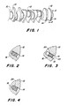
- Fig. 1 generally depicts a crankshaft 10 having a plurality of balancing members in the form of counterweights 12 thereon. Bores 14 have been formed in each counterweight as needed to balance the counterweight.
- a slug 16 of a density different from the counterweights 12 is shown inserted in the bore 14, e.g., by press fitting.
- the slug 16 can be either denser or less dense than the original material of the counterweights 12.
- suitable denser materials would include tungsten, gold, platinum,lead and various lead alloys, e.g., lead alloyed with bismuth, tin or nickel. Aluminium and various aluminium alloys would be suitable for use as materials less dense than nodular iron. while these materials are suggested as examples, they are in no way intended to be all-inclusive and any suitable material having a different density from the counterweights could be used.
- the bore 14 may be provided with a radially extending slot 24 near its innermost end, as shown in Fig. 4, or simply may be radially larger at its innermost than at its outermost end. In either situation, the slug can be held in place by upset-fitting the slug 16 into the bore 14, that is by pressing the slug 16 into the bore 14 with sufficient force that it deforms to fill the innermost portion of the bore 14. This technique also could be used with the threaded bore illustrated in Fig. 3.
- the slugs are shorter than the associated bore, and are disposed at such a position in the bore as to effect substantial balance of the crankshaft. Generally no final step of removing material from the slug is necessary except perhaps in the case of special applications where exceptionally fine balance is imperative.
- the procedure to determine the location of the bores can be conducted in the usual fashion, e.g., by hand or as taught by the references cited above, the only additional factor being to take into consideration the added mass of the slug when determining the balance points.
- the bores and slugs can be provided in balancing members other than the counterweights, e.g., vibration damping members.
- the slugs also might be fitted into the bores and welded into place.
Landscapes
- Engineering & Computer Science (AREA)
- General Engineering & Computer Science (AREA)
- Mechanical Engineering (AREA)
- Ocean & Marine Engineering (AREA)
- Physics & Mathematics (AREA)
- Acoustics & Sound (AREA)
- Aviation & Aerospace Engineering (AREA)
- Shafts, Cranks, Connecting Bars, And Related Bearings (AREA)
Applications Claiming Priority (2)
| Application Number | Priority Date | Filing Date | Title |
|---|---|---|---|
| US47838 | 1979-06-12 | ||
| US07/047,838 US4779316A (en) | 1987-05-06 | 1987-05-06 | Crankshaft and a process for balancing the same |
Publications (2)
| Publication Number | Publication Date |
|---|---|
| EP0289966A2 true EP0289966A2 (de) | 1988-11-09 |
| EP0289966A3 EP0289966A3 (de) | 1989-03-08 |
Family
ID=21951268
Family Applications (1)
| Application Number | Title | Priority Date | Filing Date |
|---|---|---|---|
| EP88106962A Withdrawn EP0289966A3 (de) | 1987-05-06 | 1988-04-30 | Verfahren zum Auswuchten einer Kurbelwelle und ausgewuchtete Kurbelwelle |
Country Status (5)
| Country | Link |
|---|---|
| US (1) | US4779316A (de) |
| EP (1) | EP0289966A3 (de) |
| JP (1) | JPS63308247A (de) |
| KR (1) | KR880014294A (de) |
| BR (1) | BR8802153A (de) |
Cited By (5)
| Publication number | Priority date | Publication date | Assignee | Title |
|---|---|---|---|---|
| EP0345424A1 (de) * | 1988-06-09 | 1989-12-13 | Dr.Ing.h.c. F. Porsche Aktiengesellschaft | Kurbelwelle |
| FR2669387A1 (fr) * | 1990-11-20 | 1992-05-22 | Fichtel & Sachs Ag | Bloc-embrayage pour un embrayage a friction equilibre et procede de fabrication. |
| CN103307090A (zh) * | 2012-03-12 | 2013-09-18 | 义乌市黑白矿山机械有限公司 | 一种凹槽式自平衡偏心轴 |
| CN103307091A (zh) * | 2012-03-12 | 2013-09-18 | 义乌市黑白矿山机械有限公司 | 一种圆柱式自平衡偏心轴 |
| CN103307092A (zh) * | 2012-03-12 | 2013-09-18 | 义乌市黑白矿山机械有限公司 | 一种平面式自平衡偏心轴 |
Families Citing this family (19)
| Publication number | Priority date | Publication date | Assignee | Title |
|---|---|---|---|---|
| AT394452B (de) * | 1990-07-13 | 1992-04-10 | Gfm Fertigungstechnik | Verfahren zum wuchtenden zentrieren teilweise spanend zu bearbeitender werkstuecke, insbesondere kurbelwellen |
| US5435059A (en) * | 1993-10-18 | 1995-07-25 | Chawla; Mohinder P. | Advance balancing process for crankshaft |
| WO1997007929A1 (en) * | 1993-10-18 | 1997-03-06 | Mohinder Paul Chawla | Advance balancing process for crankshaft |
| FR2797314B1 (fr) * | 1999-08-02 | 2002-03-22 | Renault Automation Comau | Procede d'usinage d'un vilebrequin a disposition originale de l'operation d'equilibrage et dispositif permettant de le mettre en oeuvre |
| DE10065600B4 (de) * | 2000-12-28 | 2005-11-17 | Robert Bosch Gmbh | Formwerkzeug und Verfahren zur Herstellung eines rotierend antreibbaren Bauteils |
| US6695601B2 (en) | 2002-06-07 | 2004-02-24 | Tecumseh Products Company | Self-balanced compressor crankshaft |
| DE20217172U1 (de) | 2002-11-05 | 2003-01-16 | Flam, Mirko, 72636 Frickenhausen | Auswuchtelement |
| US7509890B2 (en) * | 2004-05-27 | 2009-03-31 | International Engine Intellectual Property Company, Llc | Non-homogeneous engine component formed by powder metallurgy |
| US20050287026A1 (en) * | 2004-06-28 | 2005-12-29 | Stockhausen Joel A | Low density counterweight for eccentric driven pump |
| US8348965B2 (en) * | 2007-10-23 | 2013-01-08 | Cardiovascular Systems, Inc. | Rotational atherectomy device with counterweighting |
| US8795304B2 (en) * | 2009-06-18 | 2014-08-05 | Cardiovascular Systems, Inc. | Atherectomy device, system and method having a bi-directional distal expandable ablation element |
| US8444075B2 (en) | 2009-09-15 | 2013-05-21 | Metso Minerals Industries, Inc. | Concentrated bi-density eccentric counterweight for cone-type rock crusher |
| US8813604B2 (en) * | 2011-10-20 | 2014-08-26 | Chrysler Group Llc | Pendulum vibration absorber on a crankshaft |
| US8918994B2 (en) * | 2012-10-17 | 2014-12-30 | Ford Global Technologies, Llc | Balancing a pendulum-absorber crankshaft |
| US9482307B2 (en) | 2014-11-26 | 2016-11-01 | Caterpillar Inc. | Multi-cylinder engine crankshaft torsional vibration absorber and balancer and process thereof |
| US20170089423A1 (en) * | 2015-09-30 | 2017-03-30 | GM Global Technology Operations LLC | Crankshaft and method of balancing the same |
| US20190309792A1 (en) * | 2018-04-09 | 2019-10-10 | GM Global Technology Operations LLC | Crankshafts and methods of balancing the same |
| EP3614018A1 (de) * | 2018-07-04 | 2020-02-26 | Liebherr-Components Colmar SAS | Verbrennungsmotor |
| US10821527B2 (en) * | 2018-10-03 | 2020-11-03 | GM Global Technology Operations LLC | Method of manufacturing a crankshaft |
Family Cites Families (8)
| Publication number | Priority date | Publication date | Assignee | Title |
|---|---|---|---|---|
| US1497735A (en) * | 1919-08-11 | 1924-06-17 | United Shoe Machinery Corp | Shaft-balancing device |
| GB631520A (en) * | 1944-06-02 | 1949-11-04 | British Thomson Houston Co Ltd | Improvements in and relating to weights for rotor balancing |
| FR936262A (fr) * | 1945-11-27 | 1948-07-15 | Austin Motor Co Ltd | Perfectionnements aux amortisseurs de vibration pour pièces d'automobiles |
| US2494569A (en) * | 1947-11-19 | 1950-01-17 | Mcmaster Edward | Crankshaft balancer |
| US3537333A (en) * | 1967-11-29 | 1970-11-03 | Maybach Mercedes Benz Motorenb | Welded hollow crankshaft for a multicylinder piston-engine |
| DE1625579B2 (de) * | 1967-11-29 | 1971-07-01 | Mtu Friedrichshafen Gmbh | Geschweisste, hohle kurbelwelle fuer eine mehrzylindrige hubkolbenmaschine |
| GB1246952A (en) * | 1969-02-08 | 1971-09-22 | Continental Gummi Werke Ag | Improvements in or relating to a method of manufacturing tyres |
| US3772763A (en) * | 1971-02-17 | 1973-11-20 | Caterpillar Tractor Co | Improved lightweight crankshaft |
-
1987
- 1987-05-06 US US07/047,838 patent/US4779316A/en not_active Expired - Fee Related
-
1988
- 1988-04-30 EP EP88106962A patent/EP0289966A3/de not_active Withdrawn
- 1988-05-03 BR BR8802153A patent/BR8802153A/pt unknown
- 1988-05-06 KR KR1019880005248A patent/KR880014294A/ko not_active Withdrawn
- 1988-05-06 JP JP63110262A patent/JPS63308247A/ja active Pending
Cited By (10)
| Publication number | Priority date | Publication date | Assignee | Title |
|---|---|---|---|---|
| EP0345424A1 (de) * | 1988-06-09 | 1989-12-13 | Dr.Ing.h.c. F. Porsche Aktiengesellschaft | Kurbelwelle |
| FR2669387A1 (fr) * | 1990-11-20 | 1992-05-22 | Fichtel & Sachs Ag | Bloc-embrayage pour un embrayage a friction equilibre et procede de fabrication. |
| GB2250069A (en) * | 1990-11-20 | 1992-05-27 | Fichtel & Sachs Ag | Clutch unit for a balanced friction clutch and a process for the production thereof |
| ES2049622A2 (es) * | 1990-11-20 | 1994-04-16 | Fichtel & Sachs Ag | Unidad operativa de embrague para un embrague de friccion equilibrado y procedimiento para su fabricacion. |
| GB2250069B (en) * | 1990-11-20 | 1995-01-18 | Fichtel & Sachs Ag | Clutch unit for a balanced friction clutch and a process for the production thereof |
| CN103307090A (zh) * | 2012-03-12 | 2013-09-18 | 义乌市黑白矿山机械有限公司 | 一种凹槽式自平衡偏心轴 |
| CN103307091A (zh) * | 2012-03-12 | 2013-09-18 | 义乌市黑白矿山机械有限公司 | 一种圆柱式自平衡偏心轴 |
| CN103307092A (zh) * | 2012-03-12 | 2013-09-18 | 义乌市黑白矿山机械有限公司 | 一种平面式自平衡偏心轴 |
| CN103307091B (zh) * | 2012-03-12 | 2016-05-11 | 义乌市黑白矿山机械有限公司 | 一种用于颚式破碎机的圆柱式自平衡偏心轴 |
| CN103307092B (zh) * | 2012-03-12 | 2016-05-11 | 义乌市黑白矿山机械有限公司 | 一种用于颚式破碎机的平面式自平衡偏心轴 |
Also Published As
| Publication number | Publication date |
|---|---|
| BR8802153A (pt) | 1988-12-06 |
| US4779316A (en) | 1988-10-25 |
| EP0289966A3 (de) | 1989-03-08 |
| KR880014294A (ko) | 1988-12-23 |
| JPS63308247A (ja) | 1988-12-15 |
Similar Documents
| Publication | Publication Date | Title |
|---|---|---|
| EP0289966A2 (de) | Verfahren zum Auswuchten einer Kurbelwelle und ausgewuchtete Kurbelwelle | |
| US5535643A (en) | Anti-rattle engine balancer which drives associated oil pump | |
| EP0108543B1 (de) | Zusammenbau einer Pleuelstange und einer Kurbelwelle | |
| EP0168055A2 (de) | Läufer für Gleichstrommotor | |
| CA2253578A1 (en) | Precisely repositionable bearing cap | |
| EP0045624A1 (de) | Kegelhülse | |
| JPH0221045A (ja) | 内燃機関のバランサ装置 | |
| JP2008128486A (ja) | 自動車のエンジンにおけるカウンターウエイトの配置構造 | |
| CN109630537B (zh) | 曲轴内的椭圆形芯部的加工方法 | |
| DE102014221413A1 (de) | Kurbelwellenanordnung mit Fliehkraftpendeln | |
| KR102575108B1 (ko) | 진자 댐핑 장치를 제조하는 방법, 및 이 방법에 의해 획득된 장치 | |
| CA1303388C (en) | Crankshaft and a process for balancing the same | |
| DE2614853B2 (de) | ||
| US5273710A (en) | Process of manufacturing a member having a shaft-receiving opening | |
| US5421684A (en) | Vibration damping structure in a bolted assembly | |
| EP0476506B1 (de) | Verfahren zur Herstellung eines Zylinderblockes einer Brennkraftmaschine | |
| EP0077435B1 (de) | Kurbeltrieb für eine Brennkraftmaschine | |
| JPS62258215A (ja) | ピストン往復機械用の鉄金属材料製クランク軸 | |
| JPH07101053B2 (ja) | 平軸受の選択嵌合方法 | |
| JPS59113313A (ja) | クランク軸 | |
| EP4229316B1 (de) | Kurbelwelle für einen hubkolbenmotor mit einem gegengewicht und motor mit einer solchen kurbelwelle und montageverfahren eines solchen gegengewichts an eine solche kurbelwelle | |
| JPS6430922A (en) | Sintered oil-contained bearing | |
| JPH0219337B2 (de) | ||
| JP3111086B2 (ja) | エンジンのクランクシャフトの軸受メタル組込方法 | |
| US2359306A (en) | Engine crankshaft |
Legal Events
| Date | Code | Title | Description |
|---|---|---|---|
| PUAI | Public reference made under article 153(3) epc to a published international application that has entered the european phase |
Free format text: ORIGINAL CODE: 0009012 |
|
| AK | Designated contracting states |
Kind code of ref document: A2 Designated state(s): BE DE ES FR GB IT SE |
|
| PUAL | Search report despatched |
Free format text: ORIGINAL CODE: 0009013 |
|
| AK | Designated contracting states |
Kind code of ref document: A3 Designated state(s): BE DE ES FR GB IT SE |
|
| 17P | Request for examination filed |
Effective date: 19890308 |
|
| 17Q | First examination report despatched |
Effective date: 19900219 |
|
| STAA | Information on the status of an ep patent application or granted ep patent |
Free format text: STATUS: THE APPLICATION IS DEEMED TO BE WITHDRAWN |
|
| 18D | Application deemed to be withdrawn |
Effective date: 19910625 |