EP0289969A2 - Appareil de traitement de liquides - Google Patents
Appareil de traitement de liquides Download PDFInfo
- Publication number
- EP0289969A2 EP0289969A2 EP88106972A EP88106972A EP0289969A2 EP 0289969 A2 EP0289969 A2 EP 0289969A2 EP 88106972 A EP88106972 A EP 88106972A EP 88106972 A EP88106972 A EP 88106972A EP 0289969 A2 EP0289969 A2 EP 0289969A2
- Authority
- EP
- European Patent Office
- Prior art keywords
- insert
- cartridge
- set forth
- lower portion
- radial
- Prior art date
- Legal status (The legal status is an assumption and is not a legal conclusion. Google has not performed a legal analysis and makes no representation as to the accuracy of the status listed.)
- Withdrawn
Links
Images

Classifications
-
- C—CHEMISTRY; METALLURGY
- C07—ORGANIC CHEMISTRY
- C07K—PEPTIDES
- C07K1/00—General methods for the preparation of peptides, i.e. processes for the organic chemical preparation of peptides or proteins of any length
- C07K1/04—General methods for the preparation of peptides, i.e. processes for the organic chemical preparation of peptides or proteins of any length on carriers
- C07K1/045—General methods for the preparation of peptides, i.e. processes for the organic chemical preparation of peptides or proteins of any length on carriers using devices to improve synthesis, e.g. reactors, special vessels
-
- B—PERFORMING OPERATIONS; TRANSPORTING
- B01—PHYSICAL OR CHEMICAL PROCESSES OR APPARATUS IN GENERAL
- B01J—CHEMICAL OR PHYSICAL PROCESSES, e.g. CATALYSIS OR COLLOID CHEMISTRY; THEIR RELEVANT APPARATUS
- B01J19/00—Chemical, physical or physico-chemical processes in general; Their relevant apparatus
- B01J19/0046—Sequential or parallel reactions, e.g. for the synthesis of polypeptides or polynucleotides; Apparatus and devices for combinatorial chemistry or for making molecular arrays
-
- B—PERFORMING OPERATIONS; TRANSPORTING
- B01—PHYSICAL OR CHEMICAL PROCESSES OR APPARATUS IN GENERAL
- B01J—CHEMICAL OR PHYSICAL PROCESSES, e.g. CATALYSIS OR COLLOID CHEMISTRY; THEIR RELEVANT APPARATUS
- B01J2219/00—Chemical, physical or physico-chemical processes in general; Their relevant apparatus
- B01J2219/00274—Sequential or parallel reactions; Apparatus and devices for combinatorial chemistry or for making arrays; Chemical library technology
- B01J2219/00277—Apparatus
- B01J2219/00279—Features relating to reactor vessels
- B01J2219/00281—Individual reactor vessels
- B01J2219/00286—Reactor vessels with top and bottom openings
- B01J2219/00288—Reactor vessels with top and bottom openings in the shape of syringes
-
- B—PERFORMING OPERATIONS; TRANSPORTING
- B01—PHYSICAL OR CHEMICAL PROCESSES OR APPARATUS IN GENERAL
- B01J—CHEMICAL OR PHYSICAL PROCESSES, e.g. CATALYSIS OR COLLOID CHEMISTRY; THEIR RELEVANT APPARATUS
- B01J2219/00—Chemical, physical or physico-chemical processes in general; Their relevant apparatus
- B01J2219/00274—Sequential or parallel reactions; Apparatus and devices for combinatorial chemistry or for making arrays; Chemical library technology
- B01J2219/00277—Apparatus
- B01J2219/00279—Features relating to reactor vessels
- B01J2219/00306—Reactor vessels in a multiple arrangement
- B01J2219/00308—Reactor vessels in a multiple arrangement interchangeably mounted in racks or blocks
- B01J2219/0031—Reactor vessels in a multiple arrangement interchangeably mounted in racks or blocks the racks or blocks being mounted in stacked arrangements
-
- B—PERFORMING OPERATIONS; TRANSPORTING
- B01—PHYSICAL OR CHEMICAL PROCESSES OR APPARATUS IN GENERAL
- B01J—CHEMICAL OR PHYSICAL PROCESSES, e.g. CATALYSIS OR COLLOID CHEMISTRY; THEIR RELEVANT APPARATUS
- B01J2219/00—Chemical, physical or physico-chemical processes in general; Their relevant apparatus
- B01J2219/00274—Sequential or parallel reactions; Apparatus and devices for combinatorial chemistry or for making arrays; Chemical library technology
- B01J2219/00277—Apparatus
- B01J2219/00351—Means for dispensing and evacuation of reagents
- B01J2219/00414—Means for dispensing and evacuation of reagents using suction
- B01J2219/00416—Vacuum
-
- B—PERFORMING OPERATIONS; TRANSPORTING
- B01—PHYSICAL OR CHEMICAL PROCESSES OR APPARATUS IN GENERAL
- B01J—CHEMICAL OR PHYSICAL PROCESSES, e.g. CATALYSIS OR COLLOID CHEMISTRY; THEIR RELEVANT APPARATUS
- B01J2219/00—Chemical, physical or physico-chemical processes in general; Their relevant apparatus
- B01J2219/00274—Sequential or parallel reactions; Apparatus and devices for combinatorial chemistry or for making arrays; Chemical library technology
- B01J2219/00277—Apparatus
- B01J2219/00479—Means for mixing reactants or products in the reaction vessels
- B01J2219/00484—Means for mixing reactants or products in the reaction vessels by shaking, vibrating or oscillating of the reaction vessels
-
- B—PERFORMING OPERATIONS; TRANSPORTING
- B01—PHYSICAL OR CHEMICAL PROCESSES OR APPARATUS IN GENERAL
- B01J—CHEMICAL OR PHYSICAL PROCESSES, e.g. CATALYSIS OR COLLOID CHEMISTRY; THEIR RELEVANT APPARATUS
- B01J2219/00—Chemical, physical or physico-chemical processes in general; Their relevant apparatus
- B01J2219/00274—Sequential or parallel reactions; Apparatus and devices for combinatorial chemistry or for making arrays; Chemical library technology
- B01J2219/00277—Apparatus
- B01J2219/00497—Features relating to the solid phase supports
- B01J2219/005—Beads
-
- B—PERFORMING OPERATIONS; TRANSPORTING
- B01—PHYSICAL OR CHEMICAL PROCESSES OR APPARATUS IN GENERAL
- B01J—CHEMICAL OR PHYSICAL PROCESSES, e.g. CATALYSIS OR COLLOID CHEMISTRY; THEIR RELEVANT APPARATUS
- B01J2219/00—Chemical, physical or physico-chemical processes in general; Their relevant apparatus
- B01J2219/00274—Sequential or parallel reactions; Apparatus and devices for combinatorial chemistry or for making arrays; Chemical library technology
- B01J2219/00583—Features relative to the processes being carried out
- B01J2219/00585—Parallel processes
-
- B—PERFORMING OPERATIONS; TRANSPORTING
- B01—PHYSICAL OR CHEMICAL PROCESSES OR APPARATUS IN GENERAL
- B01J—CHEMICAL OR PHYSICAL PROCESSES, e.g. CATALYSIS OR COLLOID CHEMISTRY; THEIR RELEVANT APPARATUS
- B01J2219/00—Chemical, physical or physico-chemical processes in general; Their relevant apparatus
- B01J2219/00274—Sequential or parallel reactions; Apparatus and devices for combinatorial chemistry or for making arrays; Chemical library technology
- B01J2219/00583—Features relative to the processes being carried out
- B01J2219/0059—Sequential processes
-
- B—PERFORMING OPERATIONS; TRANSPORTING
- B01—PHYSICAL OR CHEMICAL PROCESSES OR APPARATUS IN GENERAL
- B01J—CHEMICAL OR PHYSICAL PROCESSES, e.g. CATALYSIS OR COLLOID CHEMISTRY; THEIR RELEVANT APPARATUS
- B01J2219/00—Chemical, physical or physico-chemical processes in general; Their relevant apparatus
- B01J2219/00274—Sequential or parallel reactions; Apparatus and devices for combinatorial chemistry or for making arrays; Chemical library technology
- B01J2219/00583—Features relative to the processes being carried out
- B01J2219/00596—Solid-phase processes
-
- B—PERFORMING OPERATIONS; TRANSPORTING
- B01—PHYSICAL OR CHEMICAL PROCESSES OR APPARATUS IN GENERAL
- B01J—CHEMICAL OR PHYSICAL PROCESSES, e.g. CATALYSIS OR COLLOID CHEMISTRY; THEIR RELEVANT APPARATUS
- B01J2219/00—Chemical, physical or physico-chemical processes in general; Their relevant apparatus
- B01J2219/00274—Sequential or parallel reactions; Apparatus and devices for combinatorial chemistry or for making arrays; Chemical library technology
- B01J2219/00718—Type of compounds synthesised
- B01J2219/0072—Organic compounds
- B01J2219/00725—Peptides
-
- C—CHEMISTRY; METALLURGY
- C40—COMBINATORIAL TECHNOLOGY
- C40B—COMBINATORIAL CHEMISTRY; LIBRARIES, e.g. CHEMICAL LIBRARIES
- C40B40/00—Libraries per se, e.g. arrays, mixtures
- C40B40/04—Libraries containing only organic compounds
- C40B40/10—Libraries containing peptides or polypeptides, or derivatives thereof
-
- C—CHEMISTRY; METALLURGY
- C40—COMBINATORIAL TECHNOLOGY
- C40B—COMBINATORIAL CHEMISTRY; LIBRARIES, e.g. CHEMICAL LIBRARIES
- C40B60/00—Apparatus specially adapted for use in combinatorial chemistry or with libraries
- C40B60/14—Apparatus specially adapted for use in combinatorial chemistry or with libraries for creating libraries
Definitions
- This invention relates to a fluid processing apparatus and, more particularly, to an apparatus for use with chemical synthesizers.
- These particles may be various resins and typically may be polystyrene beads having a diameter in the range of 50 - 100 microns.
- various amino acids must be linked together.
- the amino acid chain contains 100 or more amino acids, it is called a protein.
- the chemical bond between two amino acids is an amide bond and is formed by the amine group from one amino acid combining with the carboxylic group of the next.
- One of the synthesis techniques is to use a solid phase peptide synthesizer to add amino acid sequentially onto to an insoluble resin such as the polystyrene beads mentioned above. Synthesis begins with the attachment of the carboxylic end of an amino acid to the resin, and continues with one amino acid after another until the amino terminus of the desired peptide is reached. Various commercial resins are available for this purpose. The processing is usually accomplished in a non-disposable cartridge in which the various solvents and reagents necessary to the peptide synthesis are added to the cartridge, containing the beads, for each step of the synthesis process.
- the reagent After the reaction of each reagent is complete the reagent must be removed from the bead-containing cartridge, the beads washed, a new reagent added, etc. until the peptide synthesis process is complete. To speed the process it is preferable to remove the fluid reagents, solvents, etc. by applying a vacuum to the lower end of the cartridge.
- separating cartridge of this type is described by Forsythe, Jr., et al. in U.S. Patent 4,214,993 which describes a three-piece cartridge including a cap, an extraction housing, a separating column, and a primary recovery cup.
- a secondary recovery cup may also be nested onto the lower end of the waste cup.
- the primary recovery cup has interior flanges for positioning and protecting the bottom end of the column against damage.
- Each of the elements has an enlarged upper portion forming an exterior step which facilitates mounting in the swinging bucket of a centrifuge.
- the column itself may comprise particles of a suitable separatory material with the top and the bottom of the particles retained by porous supports.
- the invention is an apparatus for processing fluids having a cartridge with an enlarged middle portion adapted to receive support particles and a tubular lower portion communicating with the middle portion and having an outlet at its bottom end, the middle portion being tapered inward toward its lower end to join the lower portion of the cartridge, a closure member insertable into the top end of the cartridge, and a cap-like insert frictionally engaging the bottom end of the lower portion, the cartridge having a longitudinal axis, the improvement wherein: the insert is cylindrical, annularly fits over the lower portion, and has a discharge tip at its lower end, the tubular portion and insert being in frictional rotational engagement, each defining radial passageways which may be aligned by relative rotation therebetween about the cartridge axis to provide a fluid path between the cartridge lower portion and the discharge tip of the insert.
- the insert includes an exterior cylindrical portion annularly disposed relative to the insert and secured by a radial web to the lower end of the insert.
- the cartridge lower portion and insert lower end are each defined by inwardly tapered mating tubes, the passageways being located along the taper of each.
- the passageway in the insert is defined by a longitudinal groove in the interior wall of the insert communicating with the discharge tip.
- the cartridge defines a radial tab located at the radial position of the cartridge passageway.
- the cartridge lower portion defines a raised, exterior annular ring adapted more tightly to engage the insert.
- the inside of the insert defines an annular groove adapted to engage the cartridge ring to provide a good seal.
- the cartridge which forms a heart of the fluid processing apparatus of this invention is depicted most clearly in Figs. 1-4.
- This cartridge is adapted to contain particles which provide a solid support for the chemical reactions to take place.
- the cartridge may be insertable into the receptacles of a shaking apparatus to facilitate mixing of the cartridge reagents.
- a valve in the bottom of the cartridge may be opened or closed to permit the reagents or solvents in the cartridge to be removed. Such removal is accomplished preferably by the application of vacuum to speed up the fluid flow from the cartridge.
- the cartridge consists of three parts: A cap 10, a particulate chamber 12, and a valve insert 14.
- the cap 10 is formed integrally with a cap sheet 16 which, as may be seen more clearly in Fig. 5, is simply a sheet of plastic with a plurality of caps 10 formed therein.
- the sheet and the cap as may the other parts of the cartridge, be formed of a suitable plastic such as polypropylene. This is preferred due to the corrosive natures of the various chemistries involved.
- Each cap 10 is formed, as noted in the cap sheet 16, to have a cylindrical portion 18 adapted to fit into the top end 20 of the particulate chamber 20. To permit this construction an annular recess 22 may be formed in the cap sheet to facilitate the molding operation.
- the particulate chamber 12 comprises a top end 24, a middle portion 26, and a lower portion 28.
- the top end 24 has formed on the inner wall a raised annular ring 30 (Fig. 5) to provide a tight engagement of the cap 10 with the particulate chamber 12 so that it is securely sealed and the cartridge is supported by, and may be lifted by, the cap sheet 16.
- the middle portion 26, of slightly reduced diameter, is adapted to contain the support particles 34. The particles are retained in the middle portion 26 by a porous filter 36 which may be in the form of a ball.
- the middle portion 26 is tapered inwardly as at 40 toward the lower portion 28.
- the lower portion 28 is tubular and is further tapered inwardly at the lower end as at 42 and is formed to have a radial aperture 44 and an external radial retention ring 46.
- the lower taper 42 is closed at the lower end so that the only outlet for the particulate chamber 12 is through the radial orifice or passageway 44.
- valve insert 14 is formed to fit over the lower portion 28 of the chamber 12 in a mating relationship.
- a cylinder 50 defining an internal bore which can engage the lower portion 28 and is tapered as at 52 to conform to the taper 42 of the chamber 12 and finally is provided with an open discharge tip 54.
- An exterior cylindrical portion 56 is formed about the cylinder 50 and is attached as by a web 58 at the lower end so that the cylindrical portion 56 may flex to some extent relative to the cylinder 50.
- a radial passageway 60 is formed by a longitudinal groove along the interior of the discharge tip and the tapered portion 52 so that fluid from the orifice 44 may pass along the passageway 60 and out the discharge tip 54. This may occur only when the valve formed by the valve insert and chamber 12 is open, i.e., when the orifice 52 and the passageway 60 are in alignment by relative rotation between the valve insert 14 and the chamber 12.
- an exterior tab 64 is formed on the cylindrical portion 56 at a peripheral position corresponding to that of the passageway 60. This is used, as will be described, to position the valve insert 14 and prevent its rotation when mounted in the vacuum mounting plate (Fig. 5).
- a similar but longitudinally positioned tab 66 is positioned on the taper 36 of the chamber 12 and is in peripheral alignment with the orifice 44.
- a further alignment tab 68 is formed on the upper portion of the chamber 12.
- an interior groove 70 is formed in the insert and is adapted to engage the retentioning ring 46 of the chamber 12 so that essentially a vacuum seal is provided together with a secure connection between the insert and the chamber.
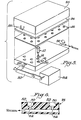
- the apparatus includes a plate having plural receptacles 80.
- Each receptacle 80 has a side recess on notch 82 to accommodate the tab 64 and is connected through a passageway 84 to a vacuum line 86.
- the vacuum line may be connected through a tube 90 to a source of vacuum.
- the plate is also adapted to be driven by a mechanical linkage 92 coupled to a drive motor 94 such that upon rotation of the drive motor 94 the linkage 92 causes the vacuum plate to be rocked back and forth through approximately 130° angle.
- the vacuum plate may be constructed of polypropylene, polyethylene, or Teflon*.
- the cap sheet 16 is used with a foam sheet 96 both of which are housed within a cover 98 which has a snap connector 100 on either end adapted to engage a slot 102 on the vacuum mounting plate such that when the cartridges are inserted in the receptacles they may be engaged by appropriate cap of the cap sheet and held in position by the cover which is snapped over the vacuum plate.
- the desired reagents which are to be mixed or washed are placed in the desired cartridge.
- the cartridge is placed in the appropriate receptacle in the vacuum plate and the cap sheet attached. Alternatively the cartridge may be attached to the cap sheet before positioning within the vacuum plate. Care must be taken to insure that the tab 64 of the valve insert be positioned in the appropriate notch 82 to prevent its rotation. This is usually accomplished with all of the tabs in alignment so that the valve is closed.
- the foam and cover are placed over the cartridges and the cover snapped into place. The motor is actuated such that the rocking motion may begin. After this is completed the cover is snapped off by releasing the snaps 100.
- the cap sheet 16 may be removed from the receptacles by pulling the cap sheet back. Then, as needed, the valves may be opened by rotation of the top portion of each cartridge so that the tabs are no longer in alignment. Vacuum may be applied and the fluid removed from the cartridge. This operation may be repeated as often as is necessary to complete the synthesis operation.
Landscapes
- Chemical & Material Sciences (AREA)
- Organic Chemistry (AREA)
- General Health & Medical Sciences (AREA)
- Genetics & Genomics (AREA)
- Health & Medical Sciences (AREA)
- Life Sciences & Earth Sciences (AREA)
- Biochemistry (AREA)
- Biophysics (AREA)
- Chemical Kinetics & Catalysis (AREA)
- Analytical Chemistry (AREA)
- Medicinal Chemistry (AREA)
- Molecular Biology (AREA)
- Proteomics, Peptides & Aminoacids (AREA)
- Separation Using Semi-Permeable Membranes (AREA)
- Multiple-Way Valves (AREA)
- Organic Low-Molecular-Weight Compounds And Preparation Thereof (AREA)
Applications Claiming Priority (2)
| Application Number | Priority Date | Filing Date | Title |
|---|---|---|---|
| US45628 | 1987-05-05 | ||
| US07/045,628 US4775629A (en) | 1987-05-05 | 1987-05-05 | Apparatus for processing fluids |
Publications (2)
| Publication Number | Publication Date |
|---|---|
| EP0289969A2 true EP0289969A2 (fr) | 1988-11-09 |
| EP0289969A3 EP0289969A3 (fr) | 1989-11-15 |
Family
ID=21939004
Family Applications (1)
| Application Number | Title | Priority Date | Filing Date |
|---|---|---|---|
| EP88106972A Withdrawn EP0289969A3 (fr) | 1987-05-05 | 1988-04-30 | Appareil de traitement de liquides |
Country Status (3)
| Country | Link |
|---|---|
| US (1) | US4775629A (fr) |
| EP (1) | EP0289969A3 (fr) |
| CA (1) | CA1298458C (fr) |
Cited By (1)
| Publication number | Priority date | Publication date | Assignee | Title |
|---|---|---|---|---|
| DE4124577A1 (de) * | 1990-07-27 | 1992-01-30 | Erba Carlo Spa | Reagensflaeschchen |
Families Citing this family (18)
| Publication number | Priority date | Publication date | Assignee | Title |
|---|---|---|---|---|
| DE3843610A1 (de) * | 1988-01-13 | 1989-07-27 | Stephan Dr Diekmann | Trenn- oder reaktionssaeuleneinheit |
| DE3814683A1 (de) * | 1988-04-30 | 1989-11-09 | Brita Wasserfilter | Siebdeckel fuer einen reinigungseinsatz in einer wasseraufbereitungsvorrichtung mit einem hohlrohr |
| AU5921690A (en) * | 1989-05-24 | 1990-12-18 | Ensys, Inc. | Method and apparatus for detecting environmental contaminants |
| DE4005518A1 (de) * | 1990-02-22 | 1991-08-29 | Boehringer Ingelheim Kg | Verfahren und vorrichtung zur simultanen synthese mehrerer polypeptide |
| JPH0794468B2 (ja) * | 1992-02-28 | 1995-10-11 | 株式会社島津製作所 | 固相法ペプチド合成用クリーベイジ処理装置 |
| EP0609431B1 (fr) * | 1992-08-24 | 1997-10-08 | Dade MicroScan Inc. | Recipient hermetique destine a la conservation et au traitement d'echantillons analytiques |
| US5603899A (en) * | 1995-04-12 | 1997-02-18 | Pharmacia Biotech, Inc. | Multiple column chromatography assembly |
| USD389572S (en) | 1996-03-22 | 1998-01-20 | Chiron Corporation | Eight vaned crown for a solid-phase reaction support pin |
| USD393065S (en) | 1996-03-22 | 1998-03-31 | Andrew Malcolm Bray | Twelve vaned crown for a solid-phase reaction support pin |
| USD392039S (en) | 1996-10-16 | 1998-03-10 | Bray Andrew M | Four-vaned crown for a solid-phase chemical reaction support |
| USD395506S (en) | 1996-10-16 | 1998-06-23 | Bray Andrew M | Eight-vaned crown for a solid-phase chemical reaction support |
| AU9317198A (en) * | 1997-09-17 | 1999-04-05 | Gentra Systems, Inc. | Apparatuses and methods for isolating nucleic acid |
| WO1999036770A1 (fr) * | 1998-01-20 | 1999-07-22 | Waters Investments Limited | Diametre interieur a double etage dans un puits d'extraction de phase solide |
| AU6524100A (en) | 1999-08-06 | 2001-03-05 | Thermo Biostar Inc. | An automated point of care detection system including complete sample processingcapabilities |
| US6503457B1 (en) * | 2000-04-14 | 2003-01-07 | Discovery Partners International, Inc. | Container and method for high volume treatment of samples on solid supports |
| US6824738B1 (en) * | 2000-04-14 | 2004-11-30 | Discovery Partners International, Inc. | System and method for treatment of samples on solid supports |
| US20020182118A1 (en) * | 2001-05-31 | 2002-12-05 | Perry Brian A. | Vacuum manifold for both multi-well plate and individual columns |
| US7284581B2 (en) * | 2006-02-15 | 2007-10-23 | Easco Hand Tools, Inc | Funnel |
Family Cites Families (8)
| Publication number | Priority date | Publication date | Assignee | Title |
|---|---|---|---|---|
| US2711846A (en) * | 1951-04-17 | 1955-06-28 | Fischer & Porter Co | Valved glass vessels such as burettes |
| US2765954A (en) * | 1955-03-22 | 1956-10-09 | Hans B Wohlbier | Dispenser head and rotatable closure therefor for containers of fluent materials |
| US3118578A (en) * | 1961-04-26 | 1964-01-21 | Pressure Dispensers Inc | Positive action dispensing valve |
| US3495463A (en) * | 1967-09-25 | 1970-02-17 | United States Steel Corp | Fluid filtering system and fluid filter therefor |
| US3567029A (en) * | 1969-08-26 | 1971-03-02 | Babington A Quame | Column for testing biological fluids |
| US3620681A (en) * | 1969-10-06 | 1971-11-16 | Eric S Wright | Apparatus for extraction of drugs and toxic substances from blood, serum and other liquid |
| US4214993A (en) * | 1978-04-03 | 1980-07-29 | E. I. Du Pont De Nemours And Company | Apparatus for separating fluids |
| US4380257A (en) * | 1981-02-02 | 1983-04-19 | E. I. Du Pont De Nemours And Company | Method and apparatus for processing fluid materials |
-
1987
- 1987-05-05 US US07/045,628 patent/US4775629A/en not_active Expired - Lifetime
-
1988
- 1988-04-30 EP EP88106972A patent/EP0289969A3/fr not_active Withdrawn
- 1988-05-03 CA CA000565654A patent/CA1298458C/fr not_active Expired - Lifetime
Cited By (1)
| Publication number | Priority date | Publication date | Assignee | Title |
|---|---|---|---|---|
| DE4124577A1 (de) * | 1990-07-27 | 1992-01-30 | Erba Carlo Spa | Reagensflaeschchen |
Also Published As
| Publication number | Publication date |
|---|---|
| CA1298458C (fr) | 1992-04-07 |
| EP0289969A3 (fr) | 1989-11-15 |
| US4775629A (en) | 1988-10-04 |
Similar Documents
| Publication | Publication Date | Title |
|---|---|---|
| US4775629A (en) | Apparatus for processing fluids | |
| US6471069B2 (en) | Device for separating components of a fluid sample | |
| US4811866A (en) | Method and apparatus for dispensing liquids | |
| JP3276148B2 (ja) | 自己位置合せ機能と自己密封機能を備えるピペット・ティップ | |
| JP3448543B2 (ja) | 少なくとも2つの製品を即席に混合して分配する装置 | |
| US7790108B2 (en) | Reagent cartridge with a reagent container for a particle-charged reagent, for non-invasive homogenization of the latter | |
| US20040265186A1 (en) | Multifunctional vacuum manifold | |
| FI87279C (fi) | Medel foer testning av naervaron av en analyt i en vaetska | |
| CN114206226A (zh) | 包括独立启动器的试样测试器以及方法 | |
| SK138394A3 (en) | Method for separating of liquid sample and device for realization of this method | |
| JPH11148937A (ja) | 隔壁を組込んだ試料収集容器用ボール及びソケット蓋 | |
| IE52698B1 (en) | Container unit | |
| US6669013B1 (en) | Disposable baby bottle | |
| AU2163200A (en) | Modular solid phase extraction plate assembly | |
| US4371015A (en) | Toner loading system having cartridge with displaceable diaphragm | |
| US4463616A (en) | Sample handling apparatus | |
| CN113507954A (zh) | 储存装置 | |
| US5456126A (en) | Fluid valve and gas sample container using same | |
| EP0612403B1 (fr) | Systeme de raccordement et microtube | |
| EP3423189B1 (fr) | Sonde d'échantillonnage pour essai de dissolution et similaire | |
| US4745073A (en) | Manual immunoassays and apparatus therefor | |
| US3800956A (en) | Vessel for chemical action | |
| US20250152147A1 (en) | Specimen collector lid having detachable handle and method | |
| HRP980617A2 (en) | Container for mixing and dosing | |
| US5139174A (en) | Method and apparatus for dispensing liquids |
Legal Events
| Date | Code | Title | Description |
|---|---|---|---|
| PUAI | Public reference made under article 153(3) epc to a published international application that has entered the european phase |
Free format text: ORIGINAL CODE: 0009012 |
|
| AK | Designated contracting states |
Kind code of ref document: A2 Designated state(s): DE FR GB IT SE |
|
| PUAL | Search report despatched |
Free format text: ORIGINAL CODE: 0009013 |
|
| AK | Designated contracting states |
Kind code of ref document: A3 Designated state(s): DE FR GB IT SE |
|
| 17P | Request for examination filed |
Effective date: 19891230 |
|
| 17Q | First examination report despatched |
Effective date: 19910318 |
|
| STAA | Information on the status of an ep patent application or granted ep patent |
Free format text: STATUS: THE APPLICATION IS DEEMED TO BE WITHDRAWN |
|
| 18D | Application deemed to be withdrawn |
Effective date: 19911001 |