EP0289981A2 - Manchon de câble en matière plastique à éléments élastiques d'étanchéité dans les domaines d'étanchéité - Google Patents
Manchon de câble en matière plastique à éléments élastiques d'étanchéité dans les domaines d'étanchéité Download PDFInfo
- Publication number
- EP0289981A2 EP0289981A2 EP88107034A EP88107034A EP0289981A2 EP 0289981 A2 EP0289981 A2 EP 0289981A2 EP 88107034 A EP88107034 A EP 88107034A EP 88107034 A EP88107034 A EP 88107034A EP 0289981 A2 EP0289981 A2 EP 0289981A2
- Authority
- EP
- European Patent Office
- Prior art keywords
- longitudinal
- sealing
- cable sleeve
- sleeve according
- seal
- Prior art date
- Legal status (The legal status is an assumption and is not a legal conclusion. Google has not performed a legal analysis and makes no representation as to the accuracy of the status listed.)
- Granted
Links
- 238000007789 sealing Methods 0.000 title claims abstract description 127
- 239000004033 plastic Substances 0.000 title claims abstract description 18
- 229920003023 plastic Polymers 0.000 title claims abstract description 18
- 239000000463 material Substances 0.000 title claims abstract description 16
- 238000013459 approach Methods 0.000 claims description 8
- 239000011148 porous material Substances 0.000 claims description 4
- 229920001296 polysiloxane Polymers 0.000 claims description 3
- 239000000565 sealant Substances 0.000 claims description 3
- 239000011256 inorganic filler Substances 0.000 claims description 2
- 229910003475 inorganic filler Inorganic materials 0.000 claims description 2
- 229920000642 polymer Polymers 0.000 claims description 2
- -1 polysiloxane Polymers 0.000 claims description 2
- 239000011343 solid material Substances 0.000 claims description 2
- 229920003051 synthetic elastomer Polymers 0.000 claims description 2
- 239000005061 synthetic rubber Substances 0.000 claims description 2
- 229920002379 silicone rubber Polymers 0.000 claims 2
- 239000004945 silicone rubber Substances 0.000 claims 2
- 230000008901 benefit Effects 0.000 description 5
- 230000006835 compression Effects 0.000 description 4
- 238000007906 compression Methods 0.000 description 4
- 230000015572 biosynthetic process Effects 0.000 description 3
- 230000000694 effects Effects 0.000 description 3
- 150000001875 compounds Chemical class 0.000 description 2
- 230000002349 favourable effect Effects 0.000 description 2
- 238000000034 method Methods 0.000 description 2
- 230000008569 process Effects 0.000 description 2
- 239000003566 sealing material Substances 0.000 description 2
- 239000004604 Blowing Agent Substances 0.000 description 1
- 229920002323 Silicone foam Polymers 0.000 description 1
- 230000009471 action Effects 0.000 description 1
- 238000004026 adhesive bonding Methods 0.000 description 1
- 238000006073 displacement reaction Methods 0.000 description 1
- 230000005489 elastic deformation Effects 0.000 description 1
- 229920001971 elastomer Polymers 0.000 description 1
- 239000006261 foam material Substances 0.000 description 1
- 238000003780 insertion Methods 0.000 description 1
- 230000037431 insertion Effects 0.000 description 1
- 230000003993 interaction Effects 0.000 description 1
- 230000004048 modification Effects 0.000 description 1
- 238000012986 modification Methods 0.000 description 1
- 239000005060 rubber Substances 0.000 description 1
- 238000000926 separation method Methods 0.000 description 1
- 238000012549 training Methods 0.000 description 1
- 230000007704 transition Effects 0.000 description 1
Images


Classifications
-
- H—ELECTRICITY
- H02—GENERATION; CONVERSION OR DISTRIBUTION OF ELECTRIC POWER
- H02G—INSTALLATION OF ELECTRIC CABLES OR LINES, OR OF COMBINED OPTICAL AND ELECTRIC CABLES OR LINES
- H02G15/00—Cable fittings
- H02G15/013—Sealing means for cable inlets
-
- H—ELECTRICITY
- H02—GENERATION; CONVERSION OR DISTRIBUTION OF ELECTRIC POWER
- H02G—INSTALLATION OF ELECTRIC CABLES OR LINES, OR OF COMBINED OPTICAL AND ELECTRIC CABLES OR LINES
- H02G15/00—Cable fittings
- H02G15/08—Cable junctions
- H02G15/10—Cable junctions protected by boxes, e.g. by distribution, connection or junction boxes
- H02G15/113—Boxes split longitudinally in main cable direction
Definitions
- the invention relates to a cable sleeve with front sealing bodies and a longitudinally divided sleeve body, the latter being applied to the sealing body via elastic, endless ring seals and in which an elastic longitudinal seal is used in the longitudinal closure area.
- the object is now achieved with a cable sleeve of the type described above in that at least the sealing elements designed as a longitudinal seal consist of foamed plastic material, that the endless ring seals are inserted in circumferential grooves of the end sealing body and the longitudinal seal in a longitudinal groove and that in the crossing areas of the ring and longitudinal seals in the inner groove wall of the longitudinal edge of the longitudinal groove, a recess is made through which the longitudinal seal protrudes with an overhang directed against the ring seal.
- the seal is used for the cable entries as well as for the parting planes of the sealing bodies on the front Licher made with a plastic sealant, since there are no major problems in these areas.
- it looks different in the joints between the sealing bodies and the socket pipe, as well as in the longitudinal area of the separation slot, because here also the use of elastic sealing material due to the requirement after opening several times.
- the major problem areas of such a sealing system are the intersections of round and longitudinal seals, especially because of the movements at these points.
- the direct contact between the round seals and the longitudinal seal is selected here, the longitudinal seal and the areas of the socket pipe at the crossing points being designed such that this direct contact can be made with the round seals.
- the sealing material of this longitudinal seal is of such an elastic property that it can be molded onto the round seals so that no gusset areas arise.
- foamed plastic, in particular for the longitudinal seals favors these properties, which is preferably a closed-pore material.
- Such a material has the following properties: - When pressing with an alternative, the same behavior results as with solid material - When pressing in a closed chamber, the volume of the air bubbles is reduced, whereby the pressure increases. The pressing force is thus the sum of the air pressure increase of the bubbles and the elastic deformation as in the first case.
- the longitudinal seal in the area of the crossing points is pressed into the groove and compressed until the elastic force is equal to the pneumatic force.
- the foam material of the longitudinal seal must be hard enough to withstand the required pressure. Elastic silicone foams with a Shore hardness of about 15 to 40 are suitable for this, for example, which have about 25% compression per 1 bar differential pressure.
- the round seal must press the longitudinal seal into the groove, so it must be stronger.
- the round cross section of the round seal is very suitable because the surface contact is relatively small and therefore relatively high surface pressure arises.
- a common round seal made of silicone tubing with 3 mm compression and 11 N / running centimeters brings about 6 bar surface pressure, which increases due to the internal pressure of the sleeve.
- the foamed plastic material can be nestled particularly well against sharp edges and corners, so that tilting movements and possibly offset closing edges can also be sealed well.
- the plastic material for the sealing elements according to the invention is preferably a high-polymer, crosslinked polysiloxane produced by using blowing agents, possibly with built-in inorganic fillers. It is also characterized by a predominantly closed-cell pore structure and can be used both with a smooth outer skin and as a cut material with the appropriate structuring.
- the plastic material has excellent heat and cold resistance and retains its elastic egg properties down to around - 60 ° C.
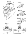
- FIG. 1 shows the cable sleeve according to the invention in principle, whereby it is indicated that here a sleeve tube 1 with a single longitudinal slot is drawn onto the two sealing bodies 10 on the front as the sleeve body.
- Each of the two sealing bodies 10 has a circumferential sealing groove, into which an endless ring seal 7 of the type described above is inserted.
- the sealing bodies 10 are divided, for example, and that cable entry openings for the introduction of cables K can be introduced in the division plane.
- the sleeve pipe 1 has along its longitudinal edges 2 and 4 a sealing system, which consists of a longitudinal groove 3 along one longitudinal edge 2 and a matching sealing spring 5 along the second longitudinal edge 4.
- the longitudinal seal 6 is inserted into the longitudinal groove 3, as will be explained in more detail below.
- Closure elements for example a closing rail, are drawn over the protruding, undercut longitudinal edges 2 and 4, with which the necessary closing pressure is generated in the sealing areas.
- the longitudinal edges 2 and 4 like the associated closing rail, are preferably wedge-shaped, which considerably simplifies the closing process.
- Figure 2 shows the intersection of an annular seal 7, which is shown here in dashed lines, and the longitudinal seal 6 along the longitudinal edges 2 and 4 of the socket pipe 1. It is shown that the inner groove wall 8 of the longitudinal edge 2 in the area of the circumferential ring seal 7 a Has recess 12, through which a projection 11 of the longitudinal seal 6 protrudes with a small projection and thus presses against the ring seal 7.
- the sealing spring 5 of the second longitudinal edge 4 has an extension 13 at this point, which fits into the recess 12 of the opposite longitudinal edge 2 and thus serves as a counter bearing for the extension 11 of the longitudinal seal 6. This ensures that direct contact of the sealing elements can take place at the intersection of the longitudinal and ring seals (6, 7), so that the desired secure sealing can be achieved in connection with the properties of the sealing elements described above.
- FIG. 3 shows the view III-III indicated in FIG. 2 and explains the conditions in the endangered crossing point.
- This shows that the ring seal 7, which is designed as a tube, is inserted in the circumferential sealing groove 9 of the sealing body 10 and that it is pressed into the elastic extension 11 of the longitudinal seal 6 without any gusset formation is, wherein - as already explained above - the ring seal 7 is harder than the longitudinal seal 6.
- a further measure for sealing in this area is to wet the sealing elements at least in these areas with a conventional plastic sealing paste, preferably based on synthetic rubber , which further supports the sealing effect.
- Figure 4 shows a second embodiment for the formation of the intersection of the longitudinal and ring seals (6, 7).
- the sealing groove is laid in a bend 14 so far outward beyond the groove edge 8 until the longitudinal seal 6 is directed against the ring seal 7 with sufficient protrusion.
- the missing groove wall 8 in this area corresponds to the recess 12 in the previous embodiment. Otherwise the conditions are the same.
- FIGS. 5 to 7 show exemplary embodiments of longitudinal seals in the areas of the crossing points.
- a longitudinal seal 6 with a square cross section is shown, the shoulder 11 being integrally formed.
- Such a seal like the associated longitudinal groove, is preferably of a slightly trapezoidal cross section, so that the insertion of the seal is facilitated.
- FIG. 6 shows a longitudinal seal 6a with a quadrangular cross-section, the shoulder 11a being subsequently used as a separate part. This has the advantage that any lengths of longitudinal seals can be cut from the piece. The approach 11a can then be fixed to the longitudinal seal, for example by gluing.
- Figure 7 shows only the difference compared to the embodiment of Figure 6, that here a round profile 6b is used with a matched approach 11b.
- FIG. 8 additionally shows a cable sleeve, the sleeve body of which is formed from two half-shells 15 and 16. According to the invention, the measures already described above are also carried out at the crossing points of the second dividing line, so that the same conditions result. This eliminates the need for further explanations.
- the advantage of the embodiment of sealing areas in the crossing points of elastic sealing elements according to the invention is that the leakages that may occur in the gusset areas between the sealing elements and the socket pipe edges are avoided. This is done with the help of profiles on the corresponding sealing edges, as will be explained in more detail below.
- the critical conditions are shown schematically in FIGS. 16, 17 and 18, as currently shown in the prior art.
- a sealing element 6 is inserted in a longitudinal groove between the two longitudinal edges 2 and 4 of a cable sleeve, as the left part of FIG. 16 shows.
- the elastic sealing element 6 is deformed in such a way that a protruding tip results.
- a second sealing element 7, for example an annular seal the sealing element 6 is pressed into the longitudinal groove, but gusset areas 18 arise along the two longitudinal edges 2 and 4 and the longitudinal seal, so that here there are leaks in the longitudinal direction.
- a second sealing element 7 for example an annular seal
- FIG. 17 now shows a sealing element 6a which is thicker than the longitudinal groove between the two longitudinal edges 2 and 4, so that it protrudes beyond the edge of the sealing groove in the open state.
- ear-shaped protuberances 19 are formed along the longitudinal edges 2 and 4, as shown in the middle part of FIG. 17, at the ends of which longitudinal gusset areas 18 are formed, since the transition jump of the protuberances 19 is not completely filled by the ring seal 7 can be.
- leaks in the longitudinal direction can also be expected in such an embodiment.
- FIG. 18 an example is shown in Figure 18, in which a sealing element 6b in the longitudinal groove between the two longitudinal edges 2 and 4 is inserted, which is thinner than the depth of the longitudinal groove.
- the sealing element 6b is laterally pressed, as shown in the middle part of FIG.
- leaky gusset areas 18 are formed by pressure from a second sealing element 7 lying above it.
- FIG. 9 shows a cable sleeve according to the invention in principle, it being indicated that here a longitudinally slotted sleeve pipe 1 is drawn onto the two end sealing bodies with the ring seal 7 as the sleeve body.
- Each of the two known sealing bodies on the end faces of the cable sleeve 1 has a circumferential sealing groove, into which an endless ring seal 7 is inserted.
- This ring seal 7 can be tubular or can also consist of foamed plastic material such as the longitudinal seal 6. From this figure, the intersection area of the ring seal 7, which is shown here in dashed lines, and the longitudinal seal 6 along the longitudinal edges 2 and 4 of the socket pipe 1 are particularly evident.
- the inner groove wall 8 of the longitudinal edge 2 has a recess 12 in the area of the circumferential ring seal 7, through which an extension 11 of the longitudinal seal 6 projects with a slight overhang and thus presses against the ring seal 7, as explained in detail in the preceding description is. It is also described there that, in contrast to this recess 12, the sealing spring 5 of the second longitudinal edge 4 has an extension 13 which fits into the recess 12 of the opposite longitudinal edge 2 and thus serves as a counter bearing for the shoulder 11 of the longitudinal seal 6. This ensures that the sealing elements can come into direct contact at the intersection of the longitudinal and ring seals.
- FIG. 10 shows a cross section through the longitudinal edges 2 and 4 of the cable sleeve 1 in the region of the intersection of the longitudinal and ring seals.
- the longitudinal groove 3 is clearly visible, which is interrupted inwards by the recess 12 here.
- the critical sealing edge 17 is again on the inner edge of the extension 13 can be seen with the indicated profiling 16. This illustration shows the still open state of the longitudinal lock.
- FIG. 11 now shows the conditions of the longitudinal closure according to FIG. 2 in the closed state with the longitudinal seal 6 inserted.
- the lateral compression of the longitudinal seal 6 causes the shoulder 11 to be raised inwards against the ring seal (not shown here). This would result in conditions such as are described in the described prior art if the profiles 20 according to the invention were not arranged along the sealing edges.
- the ring seal is not shown here.
- View V is also indicated for the following FIG. 13.
- FIG. 12 now shows a view of the sealing system in the region of the intersection of the longitudinal seal 6 with the shoulder 11 and the ring seal 7.
- the profilings 20 arranged along the sealing edges 17 are clearly recognizable, by means of which a secure sealing in the longitudinal direction according to the invention is achieved.
- FIG. 13 now shows the view of a sealing edge 17 as indicated by V in FIG. 3.
- angular notches are selected, the distance between two notch edges preferably being approximately 3 mm.
- the depth of these notches is matched to the hardness of the elastic seals used in order to achieve optimal conditions.
- both the sealing edge 17 and the edges of the profiles themselves can be adapted accordingly to the materials used, from sharp-edged to rounded.
- FIG. 14 shows part of a sealing edge 17 in which the profiling 20a is produced by rounded incisions is posed.
- profiling 20a is produced by rounded incisions is posed.
- other types of profiling can also be incorporated into the sealing edges 17 with the same mode of action.
- FIG. 15 shows an exemplary embodiment according to the invention, in which it is indicated in a plan view that a foamed plastic material can also be used for the ring seal 7a, as in the case of the longitudinal seal 6.
- This ring seal 7a is embedded in the circumferential sealing groove 9 of the sealing body 10 and is pressed sealingly against the recess 11 of the longitudinal seal 6.
Landscapes
- Gasket Seals (AREA)
Priority Applications (1)
| Application Number | Priority Date | Filing Date | Title |
|---|---|---|---|
| AT88107034T ATE99844T1 (de) | 1987-05-05 | 1988-05-02 | Kabelmuffe aus kunststoff mit elastischen dichtungselementen in den abdichtungsbereichen. |
Applications Claiming Priority (4)
| Application Number | Priority Date | Filing Date | Title |
|---|---|---|---|
| DE3714925 | 1987-05-05 | ||
| DE3714925 | 1987-05-05 | ||
| DE3727557 | 1987-08-18 | ||
| DE3727557 | 1987-08-18 |
Publications (3)
| Publication Number | Publication Date |
|---|---|
| EP0289981A2 true EP0289981A2 (fr) | 1988-11-09 |
| EP0289981A3 EP0289981A3 (en) | 1990-10-03 |
| EP0289981B1 EP0289981B1 (fr) | 1994-01-05 |
Family
ID=25855233
Family Applications (1)
| Application Number | Title | Priority Date | Filing Date |
|---|---|---|---|
| EP88107034A Expired - Lifetime EP0289981B1 (fr) | 1987-05-05 | 1988-05-02 | Manchon de câble en matière plastique à éléments élastiques d'étanchéité dans les domaines d'étanchéité |
Country Status (5)
| Country | Link |
|---|---|
| US (1) | US4845314A (fr) |
| EP (1) | EP0289981B1 (fr) |
| AU (1) | AU605861B2 (fr) |
| CA (1) | CA1336289C (fr) |
| DE (1) | DE3886808D1 (fr) |
Cited By (8)
| Publication number | Priority date | Publication date | Assignee | Title |
|---|---|---|---|---|
| DE9107913U1 (de) * | 1991-06-27 | 1991-09-05 | Stewing Kunststoffbetrieb GmbH, 4270 Dorsten | Kabelmuffe |
| EP0421254A3 (en) * | 1989-09-30 | 1991-09-11 | Stewing Kunststoffbetrieb Gmbh | Cable sleeve for connecting and tapping cables, particularly telecommunications cables |
| US5245133A (en) * | 1991-10-15 | 1993-09-14 | Thomas & Betts Corporation | Moisture-resistant cable splice and sealing structure thereof |
| US5251373A (en) * | 1991-10-15 | 1993-10-12 | Thomas & Betts Corporation | Method for protection of cable splices |
| ES2070664A2 (es) * | 1991-04-11 | 1995-06-01 | Tampella Power Oy | Unidad de combustion. |
| WO1995015602A1 (fr) * | 1993-12-01 | 1995-06-08 | Nv Raychem S.A. | Dispositif d'etancheite au milieu ambiant |
| WO1995015601A1 (fr) * | 1993-12-01 | 1995-06-08 | N.V. Raychem S.A. | Dispositif d'etancheite au milieu ambiant |
| DE19727567A1 (de) * | 1997-06-28 | 1999-02-04 | Felten & Guilleaume Energie | Abzweigklemme für ein Abzweigkabel und Hausanschlußmuffe |
Families Citing this family (8)
| Publication number | Priority date | Publication date | Assignee | Title |
|---|---|---|---|---|
| ES2080378T5 (es) * | 1991-06-27 | 2004-01-16 | Ccs Technology, Inc. | Manguito de cable. |
| US5502281A (en) * | 1993-05-27 | 1996-03-26 | Rxs Schrumpftechnik-Garnituren Gmbh | Cable sleeve of plastic composed of a slotted socket pipe and seal members at the face end |
| MY125832A (en) * | 1995-11-06 | 2006-08-30 | Japan Recom Ltd | Closure for cable connection |
| ID15837A (id) * | 1996-01-24 | 1997-08-14 | Raychem Sa Nv | Penutup kabel |
| DE59902113D1 (de) * | 1998-11-18 | 2002-08-29 | Ccs Technology Inc | Kabelmuffe aus einem umhüllungskörper und mindestens einem stirnseitigen dichtungskörper |
| DE102010043565A1 (de) * | 2010-11-08 | 2012-05-10 | Robert Bosch Gmbh | Befestigungsvorrichtung für eine Leitung und Verfahren zum Befestigen einer Leitung |
| CN102916279B (zh) * | 2011-08-04 | 2016-01-27 | 巴斯威尔股份有限公司 | 电力传输总线填充材料及其应用 |
| EP4055677A1 (fr) * | 2019-11-06 | 2022-09-14 | Eaton Intelligent Power Limited | Douille et presse-étoupe comprenant une douille |
Family Cites Families (7)
| Publication number | Priority date | Publication date | Assignee | Title |
|---|---|---|---|---|
| US2771502A (en) * | 1951-05-10 | 1956-11-20 | Bell Telephone Labor Inc | Splice closure for sheathed cable |
| US3175032A (en) * | 1961-09-19 | 1965-03-23 | Richard K Strauss | Splice cases |
| US4181814A (en) * | 1977-08-03 | 1980-01-01 | Preformed Line Products Company | Splice case with gasket and closure mechanism therefor |
| US4492816A (en) * | 1982-06-30 | 1985-01-08 | Etablissements Morel, Ateliers Electromecaniques De Favieres | Splice-protecting sleeve for electric cables or telephone cables |
| US4558174A (en) * | 1984-04-06 | 1985-12-10 | At&T Bell Laboratories | Cable closure |
| JPH0353561Y2 (fr) * | 1985-09-27 | 1991-11-22 | ||
| DE3689459D1 (de) * | 1985-10-14 | 1994-02-10 | Siemens Ag | Kabelmuffe mit stirnseitigen Dichtungskörpern und einem längsgeschlitzten Muffenrohr. |
-
1988
- 1988-04-29 US US07/188,536 patent/US4845314A/en not_active Expired - Lifetime
- 1988-05-02 EP EP88107034A patent/EP0289981B1/fr not_active Expired - Lifetime
- 1988-05-02 DE DE88107034T patent/DE3886808D1/de not_active Expired - Lifetime
- 1988-05-03 CA CA000565743A patent/CA1336289C/fr not_active Expired - Fee Related
- 1988-05-04 AU AU15552/88A patent/AU605861B2/en not_active Ceased
Cited By (11)
| Publication number | Priority date | Publication date | Assignee | Title |
|---|---|---|---|---|
| EP0421254A3 (en) * | 1989-09-30 | 1991-09-11 | Stewing Kunststoffbetrieb Gmbh | Cable sleeve for connecting and tapping cables, particularly telecommunications cables |
| TR24715A (tr) * | 1989-09-30 | 1992-03-01 | Stewing Kunststoff | Kablolarin oezellikle uzun kablolarin baglanisi ve catallanisinda kullanilan kabl |
| ES2070664A2 (es) * | 1991-04-11 | 1995-06-01 | Tampella Power Oy | Unidad de combustion. |
| DE9107913U1 (de) * | 1991-06-27 | 1991-09-05 | Stewing Kunststoffbetrieb GmbH, 4270 Dorsten | Kabelmuffe |
| US5245133A (en) * | 1991-10-15 | 1993-09-14 | Thomas & Betts Corporation | Moisture-resistant cable splice and sealing structure thereof |
| US5251373A (en) * | 1991-10-15 | 1993-10-12 | Thomas & Betts Corporation | Method for protection of cable splices |
| WO1995015602A1 (fr) * | 1993-12-01 | 1995-06-08 | Nv Raychem S.A. | Dispositif d'etancheite au milieu ambiant |
| WO1995015601A1 (fr) * | 1993-12-01 | 1995-06-08 | N.V. Raychem S.A. | Dispositif d'etancheite au milieu ambiant |
| US5792991A (en) * | 1993-12-01 | 1998-08-11 | N.V. Raychem S.A. | Environmental seal |
| DE19727567A1 (de) * | 1997-06-28 | 1999-02-04 | Felten & Guilleaume Energie | Abzweigklemme für ein Abzweigkabel und Hausanschlußmuffe |
| DE19727567C2 (de) * | 1997-06-28 | 2001-05-03 | Felten & Guilleaume Ag | Abzweigklemme für ein Abzweigkabel und Hausanschlußmuffe |
Also Published As
| Publication number | Publication date |
|---|---|
| EP0289981B1 (fr) | 1994-01-05 |
| CA1336289C (fr) | 1995-07-11 |
| DE3886808D1 (de) | 1994-02-17 |
| AU1555288A (en) | 1988-11-10 |
| US4845314A (en) | 1989-07-04 |
| AU605861B2 (en) | 1991-01-24 |
| EP0289981A3 (en) | 1990-10-03 |
Similar Documents
| Publication | Publication Date | Title |
|---|---|---|
| EP0289981B1 (fr) | Manchon de câble en matière plastique à éléments élastiques d'étanchéité dans les domaines d'étanchéité | |
| DE2304676C2 (de) | Dichtungsring aus elastomerem Material | |
| DE2503807C2 (de) | Flexibler Dichtungsring | |
| DE69206880T2 (de) | Dichtung für eine elektrische Leitungsschutzrohrkupplung und Kupplung mit dieser Dichtung | |
| DE102007030618B3 (de) | Eckverbinder für Tür- und Fensterrahmen | |
| EP3634796B1 (fr) | Système d'étanchéité | |
| WO2020030429A1 (fr) | Douille | |
| EP0059458B1 (fr) | Dispositif de liaison | |
| EP2754805B1 (fr) | Tringle de verrouillage pour une crémone | |
| AT409029B (de) | Elastische strangdichtung für fenster, türen oder dgl. | |
| EP2088275A2 (fr) | Profilé d'étanchéité de côtés, notamment pour profilés de cadre et installations de portes coulissantes en étant équipées | |
| EP3188919B1 (fr) | Dispositif d'étanchéité pour porte, système d'étanchéité pour porte et battant de porte pour véhicule ferroviaire | |
| DE3236110C2 (de) | Steckverbinder für die geradlinige Stoßverbindung von Hohlprofilen | |
| DE102011055539A1 (de) | Steckverbinder | |
| DE10210309B4 (de) | Eckverbinder | |
| CH687716A5 (de) | Beschlag. | |
| DE29808406U1 (de) | Dichtung, insbesondere für Fenster, Türen o.dgl. sowie entsprechendes Dichtungsprofil | |
| DE3337438A1 (de) | Profilleiste | |
| DE20014789U1 (de) | Geradverbindungsstück für als Distanzhalter für Isolierglasscheiben dienende Hohlprofile | |
| CH686900A5 (de) | Eckbereich eines Dichtungsrahmens fuer einen Tunneltubbing. | |
| DE9402689U1 (de) | Anschlagdichtung | |
| EP0166021B1 (fr) | Elément d'assemblage comportant une prémière et une deuxième aile, cette dernière s'éloignant d'une ligne de référence | |
| EP3722550B1 (fr) | Joint d'étanchéité doté d'une pluralité de segments comprenant respectivement une baguette d'étanchéité pouvant être abaissée | |
| DE7538640U (de) | Dichtung fuer miteinander zu verbindende profilteile aus beton o.dgl. | |
| DE29808410U1 (de) | Strangförmiges Dichtungsprofil, insbesondere für Fenster, Türen o.dgl. ("d") |
Legal Events
| Date | Code | Title | Description |
|---|---|---|---|
| PUAI | Public reference made under article 153(3) epc to a published international application that has entered the european phase |
Free format text: ORIGINAL CODE: 0009012 |
|
| AK | Designated contracting states |
Kind code of ref document: A2 Designated state(s): AT BE CH DE FR GB IT LI NL SE |
|
| PUAL | Search report despatched |
Free format text: ORIGINAL CODE: 0009013 |
|
| AK | Designated contracting states |
Kind code of ref document: A3 Designated state(s): AT BE CH DE FR GB IT LI NL SE |
|
| 17P | Request for examination filed |
Effective date: 19910307 |
|
| 17Q | First examination report despatched |
Effective date: 19920731 |
|
| GRAA | (expected) grant |
Free format text: ORIGINAL CODE: 0009210 |
|
| AK | Designated contracting states |
Kind code of ref document: B1 Designated state(s): AT BE CH DE FR GB IT LI NL SE |
|
| REF | Corresponds to: |
Ref document number: 99844 Country of ref document: AT Date of ref document: 19940115 Kind code of ref document: T |
|
| REF | Corresponds to: |
Ref document number: 3886808 Country of ref document: DE Date of ref document: 19940217 |
|
| ITF | It: translation for a ep patent filed | ||
| GBT | Gb: translation of ep patent filed (gb section 77(6)(a)/1977) |
Effective date: 19940311 |
|
| ET | Fr: translation filed | ||
| PLBE | No opposition filed within time limit |
Free format text: ORIGINAL CODE: 0009261 |
|
| STAA | Information on the status of an ep patent application or granted ep patent |
Free format text: STATUS: NO OPPOSITION FILED WITHIN TIME LIMIT |
|
| 26N | No opposition filed | ||
| EAL | Se: european patent in force in sweden |
Ref document number: 88107034.6 |
|
| PGFP | Annual fee paid to national office [announced via postgrant information from national office to epo] |
Ref country code: AT Payment date: 20000419 Year of fee payment: 13 |
|
| PGFP | Annual fee paid to national office [announced via postgrant information from national office to epo] |
Ref country code: NL Payment date: 20010419 Year of fee payment: 14 |
|
| PGFP | Annual fee paid to national office [announced via postgrant information from national office to epo] |
Ref country code: CH Payment date: 20010420 Year of fee payment: 14 |
|
| PG25 | Lapsed in a contracting state [announced via postgrant information from national office to epo] |
Ref country code: AT Free format text: LAPSE BECAUSE OF NON-PAYMENT OF DUE FEES Effective date: 20010502 |
|
| REG | Reference to a national code |
Ref country code: GB Ref legal event code: IF02 |
|
| PGFP | Annual fee paid to national office [announced via postgrant information from national office to epo] |
Ref country code: SE Payment date: 20020418 Year of fee payment: 15 |
|
| PGFP | Annual fee paid to national office [announced via postgrant information from national office to epo] |
Ref country code: GB Payment date: 20020424 Year of fee payment: 15 |
|
| PG25 | Lapsed in a contracting state [announced via postgrant information from national office to epo] |
Ref country code: CH Free format text: LAPSE BECAUSE OF NON-PAYMENT OF DUE FEES Effective date: 20020531 Ref country code: LI Free format text: LAPSE BECAUSE OF NON-PAYMENT OF DUE FEES Effective date: 20020531 |
|
| PG25 | Lapsed in a contracting state [announced via postgrant information from national office to epo] |
Ref country code: NL Free format text: LAPSE BECAUSE OF NON-PAYMENT OF DUE FEES Effective date: 20021201 |
|
| REG | Reference to a national code |
Ref country code: CH Ref legal event code: PL |
|
| NLV4 | Nl: lapsed or anulled due to non-payment of the annual fee |
Effective date: 20021201 |
|
| PG25 | Lapsed in a contracting state [announced via postgrant information from national office to epo] |
Ref country code: GB Free format text: LAPSE BECAUSE OF NON-PAYMENT OF DUE FEES Effective date: 20030502 |
|
| PG25 | Lapsed in a contracting state [announced via postgrant information from national office to epo] |
Ref country code: SE Free format text: LAPSE BECAUSE OF NON-PAYMENT OF DUE FEES Effective date: 20030503 |
|
| GBPC | Gb: european patent ceased through non-payment of renewal fee |
Effective date: 20030502 |
|
| EUG | Se: european patent has lapsed | ||
| REG | Reference to a national code |
Ref country code: FR Ref legal event code: TP |
|
| PG25 | Lapsed in a contracting state [announced via postgrant information from national office to epo] |
Ref country code: IT Free format text: LAPSE BECAUSE OF NON-PAYMENT OF DUE FEES;WARNING: LAPSES OF ITALIAN PATENTS WITH EFFECTIVE DATE BEFORE 2007 MAY HAVE OCCURRED AT ANY TIME BEFORE 2007. THE CORRECT EFFECTIVE DATE MAY BE DIFFERENT FROM THE ONE RECORDED. Effective date: 20050502 |
|
| PGFP | Annual fee paid to national office [announced via postgrant information from national office to epo] |
Ref country code: BE Payment date: 20070615 Year of fee payment: 20 |
|
| PGFP | Annual fee paid to national office [announced via postgrant information from national office to epo] |
Ref country code: DE Payment date: 20070702 Year of fee payment: 20 |
|
| PGFP | Annual fee paid to national office [announced via postgrant information from national office to epo] |
Ref country code: FR Payment date: 20070517 Year of fee payment: 20 |
|
| BE20 | Be: patent expired |
Owner name: *CCS TECHNOLOGY INC. Effective date: 20080502 |