EP0289988A1 - Outil rotatif pour l'alésage d'un trou de forage - Google Patents
Outil rotatif pour l'alésage d'un trou de forage Download PDFInfo
- Publication number
- EP0289988A1 EP0289988A1 EP88107083A EP88107083A EP0289988A1 EP 0289988 A1 EP0289988 A1 EP 0289988A1 EP 88107083 A EP88107083 A EP 88107083A EP 88107083 A EP88107083 A EP 88107083A EP 0289988 A1 EP0289988 A1 EP 0289988A1
- Authority
- EP
- European Patent Office
- Prior art keywords
- borehole
- axis
- tool
- undercutting
- bearing body
- Prior art date
- Legal status (The legal status is an assumption and is not a legal conclusion. Google has not performed a legal analysis and makes no representation as to the accuracy of the status listed.)
- Withdrawn
Links
- 238000005553 drilling Methods 0.000 claims abstract description 13
- 238000003780 insertion Methods 0.000 claims description 9
- 230000037431 insertion Effects 0.000 claims description 9
- 230000004323 axial length Effects 0.000 claims description 8
- 239000011435 rock Substances 0.000 abstract description 5
- 230000006978 adaptation Effects 0.000 abstract 1
- 238000000034 method Methods 0.000 description 25
- 238000005520 cutting process Methods 0.000 description 8
- 239000002184 metal Substances 0.000 description 8
- 101100390736 Danio rerio fign gene Proteins 0.000 description 5
- 101100390738 Mus musculus Fign gene Proteins 0.000 description 5
- 239000000463 material Substances 0.000 description 5
- 238000005096 rolling process Methods 0.000 description 3
- 230000003014 reinforcing effect Effects 0.000 description 2
- 229910000831 Steel Inorganic materials 0.000 description 1
- 238000010009 beating Methods 0.000 description 1
- 210000000078 claw Anatomy 0.000 description 1
- 238000010276 construction Methods 0.000 description 1
- 238000013016 damping Methods 0.000 description 1
- 230000003628 erosive effect Effects 0.000 description 1
- 230000001788 irregular Effects 0.000 description 1
- 238000009527 percussion Methods 0.000 description 1
- 230000002035 prolonged effect Effects 0.000 description 1
- 230000000284 resting effect Effects 0.000 description 1
- 239000010959 steel Substances 0.000 description 1
- 239000004575 stone Substances 0.000 description 1
Images





Classifications
-
- B—PERFORMING OPERATIONS; TRANSPORTING
- B23—MACHINE TOOLS; METAL-WORKING NOT OTHERWISE PROVIDED FOR
- B23B—TURNING; BORING
- B23B51/00—Tools for drilling machines
- B23B51/0018—Drills for enlarging a hole
-
- E—FIXED CONSTRUCTIONS
- E21—EARTH OR ROCK DRILLING; MINING
- E21B—EARTH OR ROCK DRILLING; OBTAINING OIL, GAS, WATER, SOLUBLE OR MELTABLE MATERIALS OR A SLURRY OF MINERALS FROM WELLS
- E21B10/00—Drill bits
- E21B10/26—Drill bits with leading portion, i.e. drill bits with a pilot cutter; Drill bits for enlarging the borehole, e.g. reamers
- E21B10/265—Bi-center drill bits, i.e. an integral bit and eccentric reamer used to simultaneously drill and underream the hole
-
- E—FIXED CONSTRUCTIONS
- E21—EARTH OR ROCK DRILLING; MINING
- E21B—EARTH OR ROCK DRILLING; OBTAINING OIL, GAS, WATER, SOLUBLE OR MELTABLE MATERIALS OR A SLURRY OF MINERALS FROM WELLS
- E21B10/00—Drill bits
- E21B10/46—Drill bits characterised by wear resisting parts, e.g. diamond inserts
- E21B10/58—Chisel-type inserts
-
- E—FIXED CONSTRUCTIONS
- E21—EARTH OR ROCK DRILLING; MINING
- E21B—EARTH OR ROCK DRILLING; OBTAINING OIL, GAS, WATER, SOLUBLE OR MELTABLE MATERIALS OR A SLURRY OF MINERALS FROM WELLS
- E21B7/00—Special methods or apparatus for drilling
- E21B7/04—Directional drilling
- E21B7/06—Deflecting the direction of boreholes
- E21B7/061—Deflecting the direction of boreholes the tool shaft advancing relative to a guide, e.g. a curved tube or a whipstock
-
- E—FIXED CONSTRUCTIONS
- E21—EARTH OR ROCK DRILLING; MINING
- E21B—EARTH OR ROCK DRILLING; OBTAINING OIL, GAS, WATER, SOLUBLE OR MELTABLE MATERIALS OR A SLURRY OF MINERALS FROM WELLS
- E21B7/00—Special methods or apparatus for drilling
- E21B7/28—Enlarging drilled holes, e.g. by counterboring
Definitions
- the invention relates to a tool according to the preamble of claim 1.
- a known drilling tool of this type is formed in one piece and has a radially protruding nose with a cutting edge at the front end of its shank which ends in a truncated tip.
- the truncated tip slides during undercut directly on the conical surface of the end portion of the borehole (DE-GM 77 38 522).
- the tool rotating during the undercutting process also executes a circular movement around the axis of the borehole in the axial section of its undercutting element.
- the shaft of the tool is supported by a spherical body via its beveled end surface, which serves as a driving surface. This lies in the conical base section of the borehole.
- the driving surface of the tool which circles on a circular line of the spherical surface, slides radially outwards in accordance with the clearing feed with simultaneous axial movement on the circular line.
- the shaft of the tool tapers in the direction of the driving surface.
- the maximum diameter of the shaft is approximately in the area of the entrance to the borehole.
- the shaft is supported there on the inner surface of the borehole, the clear width of which approximately corresponds to the maximum diameter in the input section.
- the circular movement in the section of the undercutting element is translated into a mirror-image circular movement of the drilling machine or drill-hammer machine receiving the insertion end of the tool. This requires a relatively strong circular movement in the handle area of the machine mentioned. If the structure consists of a softer stone or material, erosions can occur in the contact area of the shaft, i.e. at the entrance to the borehole, which reduces the holding force of the anchor.
- an undercut tool for rotary motion only in which the radial clearing feed of the undercutting member is generated with the aid of a working sleeve.
- This is tapered towards its front end. It surrounds the tool shank and is axially displaceably mounted on it.
- the working sleeve is pushed into the borehole with the help of a handle.
- the conical matte surface of the working sleeve is supported on the borehole wall and thereby generates the radial clearing feed.
- the end of the shaft protruding axially beyond the undercutting element lies with a rounding or a chamfer at the base of the Borehole.
- rounding off or chamfering is not suitable for generating an effective broaching feed (EP 0 211 997 A1).
- the invention has for its object to develop a tool of the type mentioned in such a way that it can be used equally in extremely hard rock or concrete in percussion drilling operations and in extremely soft rock in drilling operations and the basic requirements for producing undercuts of different shapes exist, so that it is possible to adapt to structures of different material properties and hardness, but also to extremely different requirements for the load on the dowel and for different types of dowel.
- the bearing bodies lead to correspondingly different undercuts.
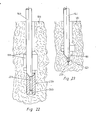
- the axial length of the undercuts if, according to claim 10, the axial length of the bearing body provided with a central bore is greater than the axial length of the pin forming the drive element, which pin more or less plunges into this central bore during the undercut process, or can penetrate into the base of the borehole in the absence of a bearing body (Fig. 23).
- a bearing body according to one of claims 5-7 or 10 can thus perform several functions by, as it were, reinforcing the base section of the borehole, determining the geometry of the undercut, centering the drilling tool relatively exactly at the end of the cutting process and the speed of the clearing progress on the building body different hardness. The latter can be done by appropriate angle of inclination of the rolling surface. In addition, relatively large tolerances with regard to a deviation of the angle of inclination of the sliding surface from the angle of inclination of the driving surface are possible.
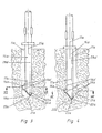
- the rotatable tool is used to produce at least one undercut 19 in a prefabricated, conically tapered borehole 11.
- the shank 14 of the tool ends in a rear insertion end 12 for receiving in a drilling or impact drilling machine.
- An undercutting member 16 projects radially out of the shaft 14 for undercutting the borehole 11.
- a driving surface 20 inclined to the borehole axis 17 cooperates with a corresponding sliding surface 21 in the borehole.
- the driving surface 20 generates in the wake of an axial working pressure on the tool a radial broaching feed of the undercutting member 16.
- the driving surface 20 lies on the sliding surface 21 and the clearing edge 16 'of the undercutting member 16 with an approximately radial orientation on the inner wall of the borehole 11 at.
- the axis 15 of the tool lies approximately in a plane passing through the borehole axis 17 and the undercutting member 16, which is referred to below as the axis plane aa.
- the driving surface 20 is formed by the end face of the wedge-like part of a wear-resistant plate (hard metal plate) serving as an undercutting member 16 and at the same time as a driving element 22.
- the driving element 22 is arranged on the end face on the shank 14 of the tool in such a way that its tip 23, which lies approximately in the axial plane aa, can be guided into an end position in an end position during the undercut process, in which it is at a distance from the borehole axis 17, in which position lies approximately in the borehole axis 17.
- the drive element 22; 22a is formed by the hard metal plate embedded in the shaft 14; 14a, which has the basic geometric shape of an irregular pentagon. A section of this hard metal plate embedded in the middle of the shaft 14; 14a, which has approximately the geometrical basic shape of an isosceles triangle, protrudes from the shaft.
- edges 16 ', 16a' enclosing an angle to one another form the clearing edges of the undercutting member 16; 16a.
- the end portion 18; 18a facing edge 16 ';16a' of the hard metal plate is extended to the tip 23; 23a of the driving element 22; 22a and includes the same angle to the vertical as the front edge forming the driving surface 20; 20a.
- the drive element 22; 22a formed by part of the hard metal cutting edge has a plane of symmetry 28 ';28a'.
- the tip 23; 23a of the drive element in the exemplary embodiments of FIGS. 1-8 formed by a vertex in which the end face of the hard metal cutting edge forming the driving surface 20; 20a collides with its adjacent clearing edge 16 ';16a'.
- FIGS. 1, 2, 5, 6 differs from the embodiment of FIGS. 3,4,7,8 essentially in that in one case the plane of symmetry 28 '(Fig. 5,6) coincides with the axis 15 of the tool and in the other case the plane of symmetry 28a' (Fig. 3,4; 7, 8) lies at a distance from the axis of symmetry 15a of the tool.
- the tool comes out of the starting position in accordance with FIGS. 1,3,5,7 in an end position according to FIGS. 2,4,6,8.
- the tool describes, at least in the axial section of the undercut 19; 19a which is formed, with its tip 23; 23a a circular motion about the borehole axis 17; 17a of increasingly smaller radius.
- the driving surface 20; 20a is supported and guided on the sliding surface 21; 21a.
- the point mentioned lies approximately in the center of the end section 18; 18a.
- FIGS. 1 in the exemplary embodiment of FIGS.
- the axis 15 of the tool is concentric with the center of the end section 18.
- the axis 15a of the tool is at the beginning of the undercutting process on the side of the borehole axis 17a facing away from the undercutting member 16a in the axis plane a-a and at the end of the undercutting process on the side of the borehole axis facing the undercutting member 16a in the mentioned axis plane aa.
- the eccentric arrangement of the tip 23a to the tool axis 15a in the example in FIGS. 3,4,7,8 desirably leads to an undercut of larger diameter in comparison to the example in FIGS. 1,2,5,6. As shown in Figs.
- the geometry of the undercut at the axial entry section is essentially determined by the angle which the drive surface 20; 20a or the sliding surface 21; 21a encloses to the vertical.
- its geometry is determined by the shape of the undercut member.
- the undercutting element and the driving element are each formed by a hard metal pin, the free end of which is conical.
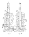
- the axis of symmetry 28b of the radially symmetrical drive element 22b coincides with the tool axis 15b.
- This also applies to the driving surface 20b formed by the lateral surface of the conical end of the driving element 22b.
- Their angle of inclination corresponds to the angle of inclination of the driving surface 20b.
- the undercutting element 16b can be formed by a plate-shaped hard metal element which, like the undercutting element in FIG the examples of FIGS. 1,2 and 3,4 protrude radially from the shaft, while the driving element as in the example of FIGS. 9.10 is designed.
- Figs. 13, 14 can be seen which enlarged cross sections according to lines XIII-XIII and XIV-XIV in FIGS. 9 and 10, the radial depth of the finished undercut (FIG. 14) is determined by the distance c between the tool axis 15b and the axis of symmetry 28b (FIG. 13) from the borehole axis 17b.
- FIGS. 11 and 12, 15, 16 differ from the exemplary embodiment in FIGS. 9.10, 13, 14 in that the axis of symmetry 28c of the driving element 22c or the driving surface 20c is arranged eccentrically to the tool axis 15c in order to achieve a larger undercut. Accordingly, the tool axis 15c is at the beginning of the undercut process, as in the example of FIGS. 9,10,13,14 at a distance c from the borehole axis 17c. At the end of the undercutting process, however, the tool axis 15c is located in the axis plane a-a on the side facing the undercutting member 16c at a distance c 'from the borehole axis 17c.
- the insertion end 12c is radially offset from the shaft 14c in such a way that the axis of this insertion end coincides with the axis 28c of the drive element 22c.
- the axis of the insertion end, the axis of symmetry 28c and the borehole axis can coincide at the end of the undercutting process. This can lead to increasing damping of the vibrations towards the end of the undercutting process.
- a plurality of tool cutting edges are arranged on the shank 14e of the tool at the same axial distance from one another as the undercutting members 16e. Therefore, there are several undercuts 19e of the same geometry in one operation in the undercut process.
- a tool cutting edge 16f is provided as the undercutting element, which is designed as in the example in FIG. 17. This also applies to the driving element 22f in relation to the driving element 22e in FIG. 17.
- the clear width of the bore 26f corresponds to the diameter of the radially symmetrical driving element 22f in its cylindrical section.
- the sliding surface 21f is formed by a conical depression in the bearing body 25f. In comparison to the exemplary embodiments described above, the sliding surface 21f is now formed by the end face of the bearing body 25f, which is preferably made of steel.
- the extreme impact resistance of the sliding surface 21f ensures that the tip 23f of the drive element 22f is precisely guided through the sliding surface 21f during the undercut process, regardless of the material properties of the structure 10f, so that the concentric position of the finished undercut is ensured.
- the axial depth of the undercut corresponds to the axial length y of the cylindrical section of the drive element 22f plus the axial extent z of the cutting element (FIG. 18).
- FIGS. 20, 21 illustrates that the conical input section of the undercut 19g is determined with respect to its angle of inclination by the angle of inclination of the sliding surface 21g of the bearing body 25g.
- the sliding surface 21g and the driving surface 20g form an angle to the vertical which is relatively small. Accordingly, the angle that encloses the end face of the shaft 14g in the conical region 14g 'to the vertical is also small.
- the bearing body 25h is extremely long and longer than the drive element 22h. This allows undercuts 19h to be made with a very large axial depth.
- This depth can be determined insofar as the undercut process can be ended if the drive element 22h penetrates into the bore 26h at different depths.
- the driving element 22i penetrates into the material of the building body 10i with its tip 23i during prolonged beating until the conical region of the end face of the shaft 14i rests on the inner wall of the conically tapering end section 18i.
- an undercut of greater axial length can be achieved.
- the bearing body 25m in Fig. 25 has a conical bearing surface 21m ', the inclination of which corresponds to the inner wall in the conically tapering end section of the associated borehole. This results in an exact centering of the bearing body 25m even if its diameter is slightly less than the clear width of the borehole.
- the sliding surface 21m includes a smaller angle to the borehole axis 17m than the support surface 21m '. This makes it clear that with the help of the assignment of different bearing bodies to the tool, sliding surfaces 21m (and accordingly the driving surfaces) can be selected that are smaller or larger than the generally fixed inclination angle, which is the conically tapering one, according to the respective requirements for the geometry of the undercut Includes end portion in the borehole to the vertical.
- the central bore 26n is a blind bore.
- the bearing body 25 o with sliding surface 21 o in FIG. 27 is to be preferred if the rock of the structure is too soft to precisely guide the driving surface of the driving element in the conically tapering end section of the borehole.
- the bearing body 25 o has essentially a reinforcing function.
- the diameter of the bearing body 25p is smaller than the clear width of the borehole 11p.
- a centering of the bearing body 25p in the borehole is produced with the help of a radially curved collar 21p 'which enlarges the rotationally symmetrical sliding surface 21p and which claws in the structure 10p.
- the collar 21p ' is bent out of an axial position (FIG. 28) with the aid of a tool 29 with a conically tapering head 30 such that a sliding surface 21p, 21p' of uniform inclination angle results.
- the bearing body 25r with sliding surface 21r can be centered and fixed with the aid of a plastic sleeve 31 with a borehole.
- the plastic sleeve 31 encloses the bearing body 25r in an upper section of smaller diameter and is radially expanded in an upper section.
Landscapes
- Engineering & Computer Science (AREA)
- Life Sciences & Earth Sciences (AREA)
- Geology (AREA)
- Mining & Mineral Resources (AREA)
- Physics & Mathematics (AREA)
- Environmental & Geological Engineering (AREA)
- Fluid Mechanics (AREA)
- General Life Sciences & Earth Sciences (AREA)
- Geochemistry & Mineralogy (AREA)
- Mechanical Engineering (AREA)
- Earth Drilling (AREA)
Applications Claiming Priority (2)
| Application Number | Priority Date | Filing Date | Title |
|---|---|---|---|
| DE19873714837 DE3714837A1 (de) | 1987-05-05 | 1987-05-05 | Rotierbares werkzeug zur herstellung einer hinterschneidung in einem bohrloch |
| DE3714837 | 1987-05-05 |
Publications (1)
| Publication Number | Publication Date |
|---|---|
| EP0289988A1 true EP0289988A1 (fr) | 1988-11-09 |
Family
ID=6326818
Family Applications (1)
| Application Number | Title | Priority Date | Filing Date |
|---|---|---|---|
| EP88107083A Withdrawn EP0289988A1 (fr) | 1987-05-05 | 1988-05-02 | Outil rotatif pour l'alésage d'un trou de forage |
Country Status (2)
| Country | Link |
|---|---|
| EP (1) | EP0289988A1 (fr) |
| DE (1) | DE3714837A1 (fr) |
Cited By (3)
| Publication number | Priority date | Publication date | Assignee | Title |
|---|---|---|---|---|
| EP0795677A2 (fr) | 1996-03-16 | 1997-09-17 | HILTI Aktiengesellschaft | Outil de forage |
| CN104632074A (zh) * | 2013-11-12 | 2015-05-20 | 西南交通建设集团股份有限公司 | 露天爆破孔防卡钻施工方法 |
| CN121138721A (zh) * | 2025-11-18 | 2025-12-16 | 大连理工大学 | 一种硬岩地质小直径桩基水磨钻挖孔施工装置及方法 |
Families Citing this family (3)
| Publication number | Priority date | Publication date | Assignee | Title |
|---|---|---|---|---|
| GB2400834B8 (en) | 2002-03-20 | 2017-06-14 | Vitec Group Plc | Improvements in or relating to tiltable mountings for payloads |
| DE10334150A1 (de) * | 2003-07-26 | 2005-02-17 | Fischerwerke Artur Fischer Gmbh & Co. Kg | Werkzeug zum Aufrauen von Bohrlöchern |
| DE102008028997B4 (de) | 2008-06-20 | 2012-03-01 | Dr. Sven Becker und Dr. Michael Bahns GbR (vertretungsberechtigter Gesellschafter: Dr. Sven Becker, 30655 Hannover) | Bohrverfahren und Bohrgerät zur Herstellung eines Bohrlochs in Erde und Gestein |
Citations (12)
| Publication number | Priority date | Publication date | Assignee | Title |
|---|---|---|---|---|
| US2362529A (en) * | 1940-08-30 | 1944-11-14 | A 1 Bit And Tool Company Ltd | Side tracking apparatus |
| US2532783A (en) * | 1946-09-30 | 1950-12-05 | Phipps Orville | Self-piloted rotary drill bit |
| DE910376C (de) * | 1944-07-12 | 1954-05-03 | Messerschmitt Boelkow Blohm | Werkzeug zum Hinterstechen von Sackloechern |
| US3001423A (en) * | 1959-03-16 | 1961-09-26 | William B Elliott | Method of forming a blind recess |
| GB961449A (en) * | 1962-03-19 | 1964-06-24 | Ass Elect Ind | Improvements relating to drills |
| DE7738522U1 (de) * | 1977-12-17 | 1978-05-24 | Millich, Adam, 7460 Balingen | Dübelbohrer |
| FR2440464A1 (fr) * | 1978-10-30 | 1980-05-30 | Perot Georges | Dispositif de forage du sol sur de courtes distances |
| DE3414206C1 (de) * | 1984-04-14 | 1985-02-21 | Norton Christensen, Inc., Salt Lake City, Utah | Drehbohrmeissel fuer Tiefbohrungen |
| GB2147036A (en) * | 1983-09-23 | 1985-05-01 | Jan Edvard Persson | A drill arrangement |
| GB2163075A (en) * | 1984-08-16 | 1986-02-19 | Sarkis Sa | Process and tool for boring cavity holes |
| EP0211997A1 (fr) * | 1985-08-30 | 1987-03-04 | Firma Mächtle GmbH | Outil de chambrage |
| EP0242638A1 (fr) * | 1986-04-15 | 1987-10-28 | Karl Eischeid | Outillage pour foret |
Family Cites Families (4)
| Publication number | Priority date | Publication date | Assignee | Title |
|---|---|---|---|---|
| DE2348211C2 (de) * | 1973-09-25 | 1983-05-26 | Hilti AG, 9494 Schaan | Bohrwerkzeug |
| DE3137938C2 (de) * | 1980-10-08 | 1983-04-28 | Wolfgang 4156 Willich Kröning | Bohrwerkzeug zur Herstellung einer hinterschnittenen Erweiterung in einer Blindbohrung |
| DE3119605C2 (de) * | 1981-05-16 | 1986-07-10 | Norton Co., Worcester, Mass. | Vorrichtung zum unterschneidenden Räumen von zylindrischen Bohrlöchern |
| DE8610234U1 (de) * | 1986-04-15 | 1987-08-20 | Eischeid, Karl, 5250 Engelskirchen | Bohrwerkzeug |
-
1987
- 1987-05-05 DE DE19873714837 patent/DE3714837A1/de not_active Withdrawn
-
1988
- 1988-05-02 EP EP88107083A patent/EP0289988A1/fr not_active Withdrawn
Patent Citations (12)
| Publication number | Priority date | Publication date | Assignee | Title |
|---|---|---|---|---|
| US2362529A (en) * | 1940-08-30 | 1944-11-14 | A 1 Bit And Tool Company Ltd | Side tracking apparatus |
| DE910376C (de) * | 1944-07-12 | 1954-05-03 | Messerschmitt Boelkow Blohm | Werkzeug zum Hinterstechen von Sackloechern |
| US2532783A (en) * | 1946-09-30 | 1950-12-05 | Phipps Orville | Self-piloted rotary drill bit |
| US3001423A (en) * | 1959-03-16 | 1961-09-26 | William B Elliott | Method of forming a blind recess |
| GB961449A (en) * | 1962-03-19 | 1964-06-24 | Ass Elect Ind | Improvements relating to drills |
| DE7738522U1 (de) * | 1977-12-17 | 1978-05-24 | Millich, Adam, 7460 Balingen | Dübelbohrer |
| FR2440464A1 (fr) * | 1978-10-30 | 1980-05-30 | Perot Georges | Dispositif de forage du sol sur de courtes distances |
| GB2147036A (en) * | 1983-09-23 | 1985-05-01 | Jan Edvard Persson | A drill arrangement |
| DE3414206C1 (de) * | 1984-04-14 | 1985-02-21 | Norton Christensen, Inc., Salt Lake City, Utah | Drehbohrmeissel fuer Tiefbohrungen |
| GB2163075A (en) * | 1984-08-16 | 1986-02-19 | Sarkis Sa | Process and tool for boring cavity holes |
| EP0211997A1 (fr) * | 1985-08-30 | 1987-03-04 | Firma Mächtle GmbH | Outil de chambrage |
| EP0242638A1 (fr) * | 1986-04-15 | 1987-10-28 | Karl Eischeid | Outillage pour foret |
Cited By (4)
| Publication number | Priority date | Publication date | Assignee | Title |
|---|---|---|---|---|
| EP0795677A2 (fr) | 1996-03-16 | 1997-09-17 | HILTI Aktiengesellschaft | Outil de forage |
| CN104632074A (zh) * | 2013-11-12 | 2015-05-20 | 西南交通建设集团股份有限公司 | 露天爆破孔防卡钻施工方法 |
| CN121138721A (zh) * | 2025-11-18 | 2025-12-16 | 大连理工大学 | 一种硬岩地质小直径桩基水磨钻挖孔施工装置及方法 |
| CN121138721B (zh) * | 2025-11-18 | 2026-02-10 | 大连理工大学 | 一种硬岩地质小直径桩基水磨钻挖孔施工装置及方法 |
Also Published As
| Publication number | Publication date |
|---|---|
| DE3714837A1 (de) | 1988-11-24 |
Similar Documents
| Publication | Publication Date | Title |
|---|---|---|
| EP2237913B9 (fr) | Outil de perçage et pointe correspondante | |
| EP0281997B1 (fr) | Fleuret à rocher | |
| EP0878261B1 (fr) | Outil de forage | |
| DE2945766C2 (de) | Bohrkrone und Bohrwerkzeug mit einer solchen Bohrkrone | |
| DE60025810T2 (de) | Bohrer | |
| DE3919363A1 (de) | Spanabhebendes werkzeug | |
| EP0470354B1 (fr) | Foret à fabriquer des trous cylindriques | |
| EP0336182B1 (fr) | Dispositif de perçage pour l'usinage de chambrages dans des trous cylindriques | |
| EP2635394A1 (fr) | Foret à langue d'aspic | |
| DE19545647A1 (de) | Drehschlag-Wendelbohrer | |
| DE19810193A1 (de) | Bohrwerkzeug | |
| WO1988006070A1 (fr) | Foret pour realiser des perçages a depouille | |
| EP0242638B1 (fr) | Outillage pour foret | |
| EP0289988A1 (fr) | Outil rotatif pour l'alésage d'un trou de forage | |
| DE102012218702A1 (de) | Gesteinsbohrer | |
| DE3143462C2 (fr) | ||
| EP3656494A1 (fr) | Foret étagé | |
| DE4222809A1 (de) | Werkzeugaggregat | |
| DE19730665A1 (de) | Bohrer | |
| CH635771A5 (en) | Tool and tool holder for a percussive or rotary-percussive hammer | |
| EP3535080B1 (fr) | Outil de perçage | |
| DE3529603C2 (fr) | ||
| EP1902801A1 (fr) | Dispositif destiné à percer un trou avec une coupe arrière conique | |
| AT522202B1 (de) | Bohrwerkzeug | |
| EP0211997A1 (fr) | Outil de chambrage |
Legal Events
| Date | Code | Title | Description |
|---|---|---|---|
| PUAI | Public reference made under article 153(3) epc to a published international application that has entered the european phase |
Free format text: ORIGINAL CODE: 0009012 |
|
| AK | Designated contracting states |
Kind code of ref document: A1 Designated state(s): CH FR LI NL |
|
| STAA | Information on the status of an ep patent application or granted ep patent |
Free format text: STATUS: THE APPLICATION HAS BEEN WITHDRAWN |
|
| 17P | Request for examination filed |
Effective date: 19890503 |
|
| 18W | Application withdrawn |
Withdrawal date: 19890519 |