EP0289991A2 - Transfer- und Verteilungssystem und -verfahren für eine katalytische Wirbelschicht-Krackanlage - Google Patents
Transfer- und Verteilungssystem und -verfahren für eine katalytische Wirbelschicht-Krackanlage Download PDFInfo
- Publication number
- EP0289991A2 EP0289991A2 EP88107100A EP88107100A EP0289991A2 EP 0289991 A2 EP0289991 A2 EP 0289991A2 EP 88107100 A EP88107100 A EP 88107100A EP 88107100 A EP88107100 A EP 88107100A EP 0289991 A2 EP0289991 A2 EP 0289991A2
- Authority
- EP
- European Patent Office
- Prior art keywords
- regenerator
- catalyst
- standpipe
- fluidized bed
- spent catalyst
- Prior art date
- Legal status (The legal status is an assumption and is not a legal conclusion. Google has not performed a legal analysis and makes no representation as to the accuracy of the status listed.)
- Withdrawn
Links
Images





Classifications
-
- C—CHEMISTRY; METALLURGY
- C10—PETROLEUM, GAS OR COKE INDUSTRIES; TECHNICAL GASES CONTAINING CARBON MONOXIDE; FUELS; LUBRICANTS; PEAT
- C10G—CRACKING HYDROCARBON OILS; PRODUCTION OF LIQUID HYDROCARBON MIXTURES, e.g. BY DESTRUCTIVE HYDROGENATION, OLIGOMERISATION, POLYMERISATION; RECOVERY OF HYDROCARBON OILS FROM OIL-SHALE, OIL-SAND, OR GASES; REFINING MIXTURES MAINLY CONSISTING OF HYDROCARBONS; REFORMING OF NAPHTHA; MINERAL WAXES
- C10G11/00—Catalytic cracking, in the absence of hydrogen, of hydrocarbon oils
- C10G11/14—Catalytic cracking, in the absence of hydrogen, of hydrocarbon oils with preheated moving solid catalysts
- C10G11/18—Catalytic cracking, in the absence of hydrogen, of hydrocarbon oils with preheated moving solid catalysts according to the "fluidised-bed" technique
- C10G11/182—Regeneration
-
- B—PERFORMING OPERATIONS; TRANSPORTING
- B01—PHYSICAL OR CHEMICAL PROCESSES OR APPARATUS IN GENERAL
- B01J—CHEMICAL OR PHYSICAL PROCESSES, e.g. CATALYSIS OR COLLOID CHEMISTRY; THEIR RELEVANT APPARATUS
- B01J8/00—Chemical or physical processes in general, conducted in the presence of fluids and solid particles; Apparatus for such processes
- B01J8/18—Chemical or physical processes in general, conducted in the presence of fluids and solid particles; Apparatus for such processes with fluidised particles
- B01J8/24—Chemical or physical processes in general, conducted in the presence of fluids and solid particles; Apparatus for such processes with fluidised particles according to "fluidised-bed" technique
- B01J8/26—Chemical or physical processes in general, conducted in the presence of fluids and solid particles; Apparatus for such processes with fluidised particles according to "fluidised-bed" technique with two or more fluidised beds, e.g. reactor and regeneration installations
Definitions
- the present invention relates to a process and apparatus for regenerating spent catalyst in fluid catalytic cracking.
- the present invention also relates to a slide joint for accommodating thermal stresses and expansions of the apparatus for regenerating spent catalyst.
- Catalysts employed in hydrocarbon conversion processes become partially deactivated due to carbonaceous deposits accumulating on the catalyst surface.
- Various methods for regenerating the catalyst by combustion with an oxidizing gas have been developed.
- U.S. Pat. No. 3,902,990 discloses a process for regenerating spent catalyst contaminated by carbonaceous deposits by contacting the spent catalyst with a hot flue gas emanating from a first dense phase regeneration zone. The heated spent catalyst is then contacted counter-currently with an oxygen-containing gas in the first dense phase regeneration zone to produce partially regenerated catalyst which is subsequently contacted concurrently with an oxygen-containing gas in a second dense phase regeneration zone.
- hydrocarbons which are contained in the void spaces of spent catalysts are removed by stripping with a stripping gas in a zone located outside of the regenerator.
- the stripped spent catalyst then flows from the stripping zone through a conduit and into the regeneration vessel.
- the spent catalyst is discharged in the upper regions of the vessel and flows in a downward direction and is contacted by a hot upflowing flue gas which combusts the coke and heats the catalyst.
- the heated catalyst then continues to flow down into the dense fluidized regeneration bed for further heating and oxidation of the carbonaceous material.
- U.S. Pat. No. 3,904,548 discloses a method and system for recovering compounds deposited on catalysts in the hydrocarbon phase and effecting regeneration of catalyst particles in a swirl-type dense fluid catalyst bed regeneration operation. These objectives are accomplished by limiting the volume of regeneration gas brought in contact with the catalyst in selected vertical segments of the regeneration zone.
- the regeneration zone is supplied with regeneration gas in the lower portion thereof by a plurality of radiating distributing grids or segments individually controlled with respect to the volume of regenerating gas desired to be passed through any given segment.
- U.S. Pat. No. 4,150,090 discloses an apparatus for regenerating spent catalyst.
- the apparatus incorporates a closed vessel having a centered stand pipe concentrically arranged within a spent catalyst distributor.
- the catalyst is carried upwardly by the distributor and is scattered evenly and concentrically about the distributor.
- the spent catalyst is deposited on or near the top of a dense phase catalyst bed by a plurality of radially extending catalyst distributor arms or troughs.
- Conduits convey a fluid such as steam to each of the radial arms to fluidize the catalyst particles and eject at least a portion of the catalyst at various points equally disposed around the circumference of a circle, thereby providing better catalyst distribution into the dense phase catalyst bed.
- a symmetrically arranged air distributor system which includes a number of transverse branches having small nozzles mounted thereon, form a grid pattern below the lower portions of the catalyst bed in the regenerator to provide air for burning the coke on the spent catalyst.
- U.S. Pat. Nos. 4,353,812, 4,434,245 and 4,439,533 all disclose a process and related apparatus for regenerating and cooling hot fluidized catalysts.
- the spent catalysts entering the regenerator are dispersed to the dense fluid bed by being deflected off a horizontal surface located above the catalyst inlet.
- the particles then flow from the dense phase fluidized bed into the shell side of a vertically oriented shell and tube heat exchanger where cooling occurs via indirect heat exchange with a cooling media circulating in the tubes.
- the cooled catalyst particles reenter the regenerator for further treatment before being discharged.
- U.S. Pat. No. 4,615,992 provides for a process and associated apparatus for limiting the vertical mixing of catalyst in a fluidized catalyst regenerator so that spent catalyst entering the regenerator will remain at the top of the fluidized bed for a longer period of time. This is accomplished by employing a generally horizontally placed baffle device located between 2 ft.-4 ft. below the catalyst bed level in the regenerator.
- the present invention relates to an improvement to a process for the catalytic cracking of a hydrocarbon feed, the hydrocarbon feed selected from the group consisting of gas oil, vacuum gas oil, cycle oil, residua, cracked stocks and mixtures thereof, in a fluid catalytic cracking (FCC) unit having a fluidized bed regenerator and a reactor.
- FCC fluid catalytic cracking
- the hydrocarbon feed is contacted with a cracking catalyst at elevated temperatures thus cracking a majority of the hydrocarbon feed to distillate products and in addition producing a spent catalyst laden with coke (stripped of occuled hydrocarbons).
- the spent catalyst is removed from the reactor and is regenerated by combustion with air in the regenerator, and the regenerated catalyst is recycled to the reactor.
- the improvement to the invention comprises using a regenerator which is side by side with the reactor in the fluid catalytic cracking unit, wherein air is introduced into the bottom of the regenerator for forming a fluidized bed characterized as being rich in oxygen in the lower portion of the fluidized bed and essentially depleted of oxygen in the upper portion of the fluidized bed; and introducing and distributing the spent catalyst to the upper portion of the fluidized bed of the regenerator, wherein the air used for combustion is essentially depleted of oxygen.
- the coke on the spent catalyst is allowed to burn off at a controlled rate, thus the catalyst temperature is maintained at a level which avoids sintering of the catalyst and prevents the release of steam in the lower portion of the fluidized bed.
- the present invention also relates to an apparatus for accomplishing the process in an FCC unit. Finally the present invention relates to a slide joint to accommodate thermal expansions of the apparatus for accomplishing the utilization of the process of the present invention.
- fresh feed is introduced in the process via line 10.
- the fresh feed is combined with regenerated fluid catalyst which exits regenerator 40 via line 12 to form a combined fresh feed/catalyst reactor feed stream.
- This combined fresh feed/catalyst stream is then fed to FCC reactor 30 via riser 14.
- recycle feed introduced into the process via line 20 is united with regenerated catalyst exiting regenerator 40 via line 22 to form a recycle feed/catalyst reactor feed stream, which is fed to FCC reactor 30 via riser 24.
- steam is introduced into FCC reactor 30 via line 26 to maintain proper fluidization in FCC reactor 30.
- the fresh feed and recycle streams are catalytically cracked in risers 14 and 24 and in FCC reactor 30, converting a predominantly 650°F plus hydrocarbon feedstock into distillate products.
- the distillate product is removed from FCC reactor 30 in line 28.
- the spent catalyst is separated from the hydrocarbon/catalyst mixture in stripper section 32 of FCC reactor 30 and is then fed to standpipe 34 for transport to regenerator 40.
- standpipe 34 the spent catalyst flows by gravity from the bottom of stripper section 32 of FCC reactor 30 to its entrance into regenerator 40 via tangential opening 38. Flow in standpipe is controlled via slide valve 36.
- regenerator 40 As mentioned earlier, the spent catalyst is tangentially fed to a lower portion of regenerator 40. Inside regenerator 40 the spent catalyst is combusted with air which is fed to regenerator via line 50 and distributed in regenerator 40 with air distribution rings 52. In regenerator 40, the spent catalyst is regenerated and subsequently recycled along with the feed streams to FCC reactor 30.
- regenerator temperatures increased to 1300-1350°F. This concentrated coke and the high air rate leads to a rapid initial burning rate at the inlet location, e.g. opening 38 of Figure 1, which results in excessive particle temperatures and increased deactivation. Particle temperatures can be 200 to 400°F higher than the average bed temperatures.
- the initial burning rate in this area is so high that oxygen is rapidly depleted, and CO is formed. ln regions remote to the spent catalyst introduction point, the carbon on catalyst is lower and results in high amounts of excess oxygen above the bed. When the CO-containing stream meets the oxygen-containing stream, afterburning results.
- the present invention provides a solution to the above problems through an arrangement of standpipes, liftwells, sealwells and a catalyst distributor, in addition to a special mechanical feature which provides for the large thermal growth of the components of the apparatus under regeneration temperatures.
- the present invention is an improvement to a process for the fluid catalytic cracking of a hydrocarbon feedstream which utilizes a side by side fluid catalytic cracking unit design for its reactor and regenerator.
- the improvement to the process comprises the transporting of the spent catalyst from the stripper section of the reactor to a liftwell located in the axial center of the regenerator and, generally but not necessarily, supported on the bottom of the regenerator or the wall of the regenerator.
- the spent catalyst is then lifted from the bottom of the liftwell to a catalyst distributor, which in most cases is a series of downwardly sloping troughs with an aeration source located in each trough, for a moderately uniform distribution of the spent catalyst into the upper portion of the regenerator fluidized bed.
- This improvement to the process allows for the uniform distribution of the catalyst at the top of the regenerator fluidized bed where the combustion air is essentially depleted of oxygen.
- This initial contact with depleted oxygen combustion air allows the coke on the spent catalyst to burn off at a slow controlled rate, thus keeping particle temperatures at a reasonable level to avoid sintering and allow the release of steam in the upper part of the fluidized bed, thus minimizing contact of the steam with the high temperature catalyst in the lower part of the bed.
- the present invention is also an improvement to the process by allowing the excess oxygen required to suppress CO afterburning above the bed to be minimized. This gives more coke burning capacity per pound of combustion air so that higher conversion or increased throughput can be achieved for a fixed amount of combustion air available. Alternatively, capital investment for the air blower is minimized for a predetermined conversion and throughput rate.
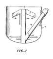
- Figures 3 and 5 further detail the liftwell region of the regenerator.
- Figures 2-7 and Figure 1 utilizes common numbers for common features.
- fresh feed is introduced in the process via line 10.
- the fresh feed is combined with regenerated fluid catalyst which exits regenerator 40 via line 12 to form a combined fresh feed/catalyst reactor feed stream.
- This combined fresh feed/catalyst stream is then fed to FCC reactor 30 via riser 14.
- recycle feed introduced into the process via line 20 is united with regenerated catalyst exiting regenerator 40 via line 22 to form a recycle feed/catalyst reactor feed stream, which is fed to FCC reactor 30 via riser 24.
- steam is introduced into FCC reactor 30 via line 26 to maintain proper fluidization in FCC reactor 30.
- the fresh feed and recycle streams are catalytically cracked in risers 14 and 24 and in FCC reactor 30, converting a predominantly 650°F plus hydrocarbon feedstock into distillate products.
- the distillate product is removed from FCC reactor 30 in line 28.
- the spent catalyst is separated from the hydrocarbon/catalyst mixture in stripper section 32 of FCC reactor 30 and is then fed to standpipe 34 for transport to regenerator 40.
- standpipe 34 the spent catalyst flows from the bottom of stripper section 32 of FCC reactor 30 to the bottom of center liftwell 44 in the radial center of regenerator 40. Flow in standpipe 34 is controlled via slide valve 36.
- Fluidization air is provided to the bottom of the liftwell through air distributor 42. Fluidization air provided to air distributor 42 and to aid the flow of the spent catalyst in standpipe 34 is provided via line 60. Once the spent catalyst is lifted to the top of liftwell 44, it is fed to catalyst distributor 46.
- Catalyst distributor 46 can be of any type or design, examples of catalyst distributors are disclosed in U.S. pat. Nos. 4,150,090 and 4,615,992, which are incorporated herein by reference. Although any type of catalyst distributor can be used, the preferred distributor is a series of radially extending, downward sloping troughs.
- the catalyst flows down the troughs and is dispersed into the fluidized bed of regenerator 40 via fluidizing air which has been introduced into the bottom of troughs via air lines 48. Inside regenerator 40 the spent catalyst is then combusted with air which is fed to regenerator via line 50 and distributed in regenerator 40 with air distribution rings 52. In regenerator 40, the spent catalyst is regenerated and subsequently recycled along with the feed streams to FCC reactor 30.
- Another configuration of the present invention is to utilize a second internal liftwell to aid in transporting the spent catalyst from stripper section 32 of reactor 30 to the bottom of the center internal liftwell.
- fresh feed is introduced in the process via line 10.
- the fresh feed is combined with regenerated fluid catalyst which exits regenerator 40 via line 12 to form a combined fresh feed/catalyst reactor feed stream.
- This combined fresh feed/catalyst stream is then fed to FCC reactor 30 via riser 14.
- recycle feed introduced into the process via line 20 is united with regenerated catalyst exiting regenerator 40 via line 22 to form a recycle feed/catalyst reactor feed stream, which is fed to FCC reactor 30 via riser 24.
- FCC reactor 30 steam is introduced into FCC reactor 30 via line 26 to maintain proper fluidization in FCC reactor 30.
- the fresh feed and recycle streams are catalytically cracked in risers 14 and 24 and in FCC reactor 30, converting a predominantly 650°F plus hydrocarbon feedstock into distillate products.
- the distillate product is removed from FCC reactor 30 in line 28.
- the spent catalyst is separated from the hydrocarbon/catalyst mixture in stripper section 32 of FCC reactor 30 and is then fed to standpipe 34 for transport to regenerator 40.
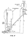
- standpipe 34 the spent catalyst flows from the bottom of stripper section 32 of FCC reactor 30 to the bottom of an internal sealwell 37 located near the external wall of regenerator 40.
- the spent catalyst is then fed into connecting internal standpipe 41 for transport to the bottom of internal standpipe 44 located in the radial center of regenerator 40.
- Flow in standpipe 34 is controlled via slide valve 36.
- Spent catalyst discharging from slide valve 36 accumulates in sealwell 37 to a level such that the static head pressure of the fluidized catalyst in sealwell 37 and internal standpipe 41 overcomes the frictional and static head pressure drop of liftwell 44 and the regenerator fluidized bed above it.
- the fluidized catalyst level in sealwell 37 is self-adjusting so that the above is true for any combinations of flow and catalyst density in liftwell 44 and internal standpipe 41.
- the extended length of sealwell 37 assures that it will not overflow during normal operation.
- Fluidization air is provided to the bottom of the liftwell through air distributor 42. Fluidization air provided to air distributors 42 and 39 and aeration air to aid the flow of the spent catalyst in standpipe 41 is provided via line 60.
- catalyst distributor 46 is a series of radially extending, downward sloping troughs. The catalyst flows down the troughs and is dispersed into the fluidized bed of regenerator 40 via fluidizing air which has been introduced into the bottom of troughs via air lines 48. Inside regenerator 40 the spent catalyst is then combusted with air which is fed to regenerator via line 50 and distributed in regenerator 40 with air distribution rings 52. In regenerator 40, the spent catalyst is regenerated by oxidation of deposited coke and subsequently recycled along with the feed streams to FCC reactor 30.
- Figure 5 details the lower section of regenerator 40 as depicted in Figure 4. With reference to Figure 5, a more detailed depiction of internal sealwell 37 and liftwell 44, internal standpipe 41, catalyst distributor 46 and air distributors 52 and 48 are shown.
- configuration 3 like configuration 2, configuration 3, as shown in Figure 6, utilizes an intermediate sealwell to help with the transport of the spent catalyst from the bottom of stripper section 32 to the bottom of internal liftwell 44, however in the Figure 6 configuration the intermediate sealwell is externally located.
- fresh feed is introduced in the process via line 10. After introduction into the process, the fresh feed is combined with regenerated fluid catalyst which exits regenerator 40 via line 12 to form a combined fresh feed/catalyst reactor feed stream. This combined fresh feed/catalyst stream is then fed to FCC reactor 30 via riser 14.
- recycle feed introduced into the process via line 20 is united with regenerated catalyst exiting regenerator 40 via line 22 to form a recycle feed/catalyst reactor feed stream, which is fed to FCC reactor 30 via riser 24.
- steam is introduced into FCC reactor 30 via line 26 to maintain proper fluidization in FCC reactor 30.
- the fresh feed and recycle streams are catalytically cracked in risers 14 and 24 and in FCC reactor 30, converting a predominantly 650°F plus hydrocarbon feedstock into distillate products.
- the distillate product is removed from FCC reactor 30 in line 28.
- the spent catalyst is separated from the hydrocarbon/catalyst mixture in stripper section 32 of FCC reactor 30 and is then fed to standpipe 34 for transport to regenerator 40.
- standpipe 34 the spent catalyst flows from the bottom of stripper section 32 of FCC reactor 30 to the bottom of an external sealwell 61 located against and outside the external wall of regenerator 40.
- the spent catalyst is then fed into connecting standpipe 64 for transport to the bottom of internal standpipe 44 located in the radial center of regenerator 40. Flow in standpipe 34 is controlled via slide valve 36.
- Spent catalyst discharging from slide valve 36 accumulates in external sealwell 61 to a level such that the static head pressure of the fluidized catalyst in external sealwell 61 and connecting standpipe 64 overcomes the frictional and static head pressure drop of liftwell 44 and the regenerator fluidized bed above it.
- the fluidized catalyst level in sealwell 61 is self-adjusting so that the above is true for any combinations of flow and catalyst density in liftwell 44 and connecting standpipe 64.
- the extended length of sealwell 61 assures that it will not overflow during normal operation.
- a ventpipe allows fluidization air introduced by distributor 62 to flow into the upper portion of regenerator 40.
- Fluidization air is provided to the bottom of liftwell 44 through air distributor 42. Fluidization air provided to air distributors 42 and 62 and aeration air to aid the flow of the spent catalyst in standpipe 64 is provided via line 60. Once the spent catalyst arrives at the top of liftwell 44, it is fed to catalyst distributor 46.
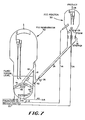
- configuration 4 does not utilize an center internal liftwell but uses an external sealwell and a proboscis-like standpipe to feed the catalyst distributor.
- fresh feed is introduced in the process via line 10.
- the fresh feed is combined with regenerated fluid catalyst which exits regenerator 40 via line 12 to form a combined fresh feed/catalyst reactor feed stream.
- This combined fresh feed/catalyst stream is then fed to FCC reactor 30 via riser 14.
- recycle feed introduced into the process via line 20 is united with regenerated catalyst exiting regenerator 40 via line 22 to form a recycle feed/catalyst reactor feed stream, which is fed to FCC reactor 30 via riser 24.
- FCC reactor 30 steam is introduced into FCC reactor 30 via line 26 to maintain proper fluidization in FCC reactor 30.
- the fresh feed and recycle streams are catalytically cracked in risers 14 and 24 and in FCC reactor 30, converting a predominantly 650°F plus hydrocarbon feedstock into distillate products.
- the distillate product is removed from FCC reactor 30 in line 28.
- the spent catalyst is separated from the hydrocarbon/catalyst mixture in stripper section 32 of FCC reactor 30 and is then fed to standpipe 34 for transport to regenerator 40.
- standpipe 34 the spent catalyst flows from the bottom of stripper section 32 of FCC reactor 30 to the bottom of an external sealwell 61 located against the external wall of regenerator 40.
- the spent catalyst is then fed into standpipe 64 for transport to the catalyst distributor 46.
- standpipe 64 the spent catalyst is distributed to the troughs of catalyst distributor 46 by means of fluidization air provided from air distributor 66.
- Flow in standpipe 34 is controlled via slide valve 36. Fluidization air provided to air distributors 62 and 66 and to aid the flow of the spent catalyst in standpipe 64 is provided via line 60.
- the steepest possible angle must be maintained to avoid gas separation from the fluidized gas-solids mixture. Such separation would cause catalyst deaeration and consequent loss of flow.
- the steeper the angle of spent catalyst standpipe 34 the less likelihood that deaeration will occur.
- the minimum angle of inclination of standpipe 34, that will support fluidized flow is dependent on certain catalyst properties such as (1) density and (2) particle size distribution as well as other process variables. Deaeration can also occur as a result of changes in direction of the transport piping in the horizontal plane and therefore such piping directional changes are to be avoided.
- the discharge of the stripper is oriented such that the spent catalyst standpipe intersects a single liftwell located in the center of the regenerator (Fig. 2).
- a sealwell located either internal or external to the regenerator and being additional to the regenerator internal center liftwell allows adherence to the above-discussed concepts that promote flow (Fig. 4 and Fig. 6).
- Aeration is provided at the base of the liftwell and sealwell to keep the catalyst in a fluidized condition.
- the sealwells 37 and 61 are vented at their tops in order that the aeration gas does not pocket at the top of the sealwell and inhibit flow.
- the vent gas from external sealwell 61 is introduced back into the regenerator.
- a principal problem that was overcome in each of the liftwell and sealwell designs is the stress and strain that results when equipment that is fabricated and installed at ambient temperatures is elevated to an operating temperature of 1300-1350°F.
- the growth of the constituent metal components due to thermal expansion and the simultaneous decrease in the strength of those components necessitates that, where possible, parts should not be restrained in the direction of their thermal growth.
- the liftwell and sealwells pose no severe problem in this regard as they are free to grow, since at least one end need not connect with any particular other component.
- the internal spent catalyst standpipe is provided with a unique joint that allows for thermal expansion, rotation and misalignment.
- the "slip joint” takes into account the thermal growth and movement of the internal spent catalyst stand pipe relative to its juncture with the regenerator center well.
- the slip joint uses a braided stainless steel hose, employed as a packing material, which is compressed upon installation.
- An important aspect of the slip joint is the specific amount of that compression.
- Significant wearing of a channel through the annulus would thereby be a possibility and the eventual short-circuiting of catalyst flow would adversely affect the intended process performance of the equipment since spent catalyst would discharge almost directly into the withdrawal lines 22 and 12.
- the follower ring also assures that the braided hose packing material cannot inadvertently dislodge from the annular space during operation of the equipment.
- the follower ring features a positive stop which assures that, upon installation, the total compression of the braided hose packing is as designed.
- the compression fit of the braided hose packing within the slip joint annular space results in the occurrence of a frictional resistive force between the braided hose packing and the surface of the internal spent catalyst standpipe as thermal expansion elongates the internal spent catalyst standpipe on startup and shutdown. This force is trivial, however, as compared to the strengths of the various components involved and is of little consequence. It does not significantly inhibit the 4"-5" axial motion of the internal spent catalyst standpipe as operating temperature is reached.
- a further feature of the slip joint is the redundance of the convolutions of packing material. This feature assures that should localized tearing, abrading or other such damage in fact inadvertently occur, then an inside-to-outside open channel would still not exist.
- An additional feature of the slip joint is the application of a hard surfacing layer to inhibit erosion should the above measures fail to assure the integrity of the braided hose packing as a sealing member.
- both spent catalyst standpipe 34 and center liftwell 44 undergo significant thermal expansion in different directions as they heat up from shutdown to operating temperatures. Success of the invention is dependent upon providing a means of avoiding enormous stresses that would be generated in a fixed system.
- Conventional technology for alleviating such stresses in catalyst standpipes and risers is to employ bellows like expansion joints. These expansion joints have proved satisfactory in services where the exterior of the joint is exposed to the atmosphere. The usage of such an expansion joint was considered for service on the internal regenerator portion of standpipe 34 between liftwell 44 and the external wall of regenerator 40, but such a use was rejected because of the possibility of catalyst packing the bellows and other moving parts and thus prevent its proper operation.
- spent catalyst standpipe 34 is rigidly attached to the wall of regenerator 40 using a thermal sleeve arrangement 35.
- the juncture between standpipe 34 and liftwell 44 is arranged as a slide joint 45 so that the major thermal expansion of standpipe 34 along its longitudinal axis can be accommodated as well as the slight angular misalignment caused by the differences in the expansion of liftwell 44 and the regenerator wall 40.
- slide joint 45 includes standpipe 34 arranged as a male piece inserted into female socket 144 which is constructed as an integral part of liftwell 44.
- Reasonable clearances are needed between standpipe 34 and socket 144 to accommodate angular misalignment and to allow for ease of construction.
- Packing retention ring 102 is installed with conventional bolting techniques.
- the interior surfaces 108 and 109 of packing retention ring 102 and packing retention land 103 are surface hardened to prevent galling in the event of metal to metal contact.
- standpipe 34 and liftwell 44 are lined with hexmesh and refractory system 106 for erosion protection.
- API Gravity °API 23.6 Sulfur: wt% 1.34 Basic Nitrogen: wppm 277 Conradson Carbon Residue: wt% 0.67
Landscapes
- Chemical & Material Sciences (AREA)
- Engineering & Computer Science (AREA)
- Chemical Kinetics & Catalysis (AREA)
- Oil, Petroleum & Natural Gas (AREA)
- Organic Chemistry (AREA)
- General Chemical & Material Sciences (AREA)
- Combustion & Propulsion (AREA)
- Production Of Liquid Hydrocarbon Mixture For Refining Petroleum (AREA)
- Devices And Processes Conducted In The Presence Of Fluids And Solid Particles (AREA)
Applications Claiming Priority (2)
| Application Number | Priority Date | Filing Date | Title |
|---|---|---|---|
| US4738087A | 1987-05-07 | 1987-05-07 | |
| US47380 | 1987-05-07 |
Publications (2)
| Publication Number | Publication Date |
|---|---|
| EP0289991A2 true EP0289991A2 (de) | 1988-11-09 |
| EP0289991A3 EP0289991A3 (de) | 1990-01-17 |
Family
ID=21948633
Family Applications (1)
| Application Number | Title | Priority Date | Filing Date |
|---|---|---|---|
| EP88107100A Withdrawn EP0289991A3 (de) | 1987-05-07 | 1988-05-03 | Transfer- und Verteilungssystem und -verfahren für eine katalytische Wirbelschicht-Krackanlage |
Country Status (2)
| Country | Link |
|---|---|
| EP (1) | EP0289991A3 (de) |
| JP (1) | JPS6438493A (de) |
Cited By (10)
| Publication number | Priority date | Publication date | Assignee | Title |
|---|---|---|---|---|
| EP0457540A1 (de) * | 1990-05-15 | 1991-11-21 | Exxon Research And Engineering Company | Katalysatorverteilungssystem für Regeneratoren von FCC-Anlagen |
| EP0773275A1 (de) * | 1995-11-13 | 1997-05-14 | The M.W. Kellogg Company | Selbstbelüftender Verteiler von gebrauchtem Katalysator |
| WO2010045873A1 (zh) * | 2008-10-24 | 2010-04-29 | Di Dan | 流态化水平循环组合反应装置 |
| US7803326B2 (en) | 2007-08-01 | 2010-09-28 | Uop Llc | Hydrocarbon conversion unit including a reaction zone receiving transferred catalyst |
| US7811447B2 (en) | 2007-08-01 | 2010-10-12 | Uop Llc | Method of transferring particles from one pressure zone to another pressure zone |
| US9233354B1 (en) | 2014-07-31 | 2016-01-12 | Uop Llc | Sealing system for a fluid catalyst cracking regenerator |
| WO2016182786A1 (en) * | 2015-05-11 | 2016-11-17 | Shell Oil Company | Fluidized solids distributor |
| US11009229B2 (en) | 2016-02-29 | 2021-05-18 | Uop Llc | Method for fluidizing spent catalyst |
| CN115501823A (zh) * | 2021-06-23 | 2022-12-23 | 中国石油化工股份有限公司 | 流化床反应器和制备低碳烯烃的装置以及制备低碳烯烃的方法 |
| US12025249B2 (en) * | 2018-04-05 | 2024-07-02 | Petroleo Brasileiro S.A.-Petrobras | Telescopic joint |
Family Cites Families (2)
| Publication number | Priority date | Publication date | Assignee | Title |
|---|---|---|---|---|
| US3902990A (en) * | 1974-03-18 | 1975-09-02 | Exxon Research Engineering Co | Catalyst regeneration process and apparatus |
| US4615992A (en) * | 1985-04-02 | 1986-10-07 | Air Products And Chemicals, Inc. | Catalyst regeneration process with improved catalyst distribution in a fluidized bed |
-
1988
- 1988-05-03 EP EP88107100A patent/EP0289991A3/de not_active Withdrawn
- 1988-05-06 JP JP63110276A patent/JPS6438493A/ja active Pending
Cited By (14)
| Publication number | Priority date | Publication date | Assignee | Title |
|---|---|---|---|---|
| EP0457540A1 (de) * | 1990-05-15 | 1991-11-21 | Exxon Research And Engineering Company | Katalysatorverteilungssystem für Regeneratoren von FCC-Anlagen |
| EP0773275A1 (de) * | 1995-11-13 | 1997-05-14 | The M.W. Kellogg Company | Selbstbelüftender Verteiler von gebrauchtem Katalysator |
| US7803326B2 (en) | 2007-08-01 | 2010-09-28 | Uop Llc | Hydrocarbon conversion unit including a reaction zone receiving transferred catalyst |
| US7811447B2 (en) | 2007-08-01 | 2010-10-12 | Uop Llc | Method of transferring particles from one pressure zone to another pressure zone |
| WO2010045873A1 (zh) * | 2008-10-24 | 2010-04-29 | Di Dan | 流态化水平循环组合反应装置 |
| US9233354B1 (en) | 2014-07-31 | 2016-01-12 | Uop Llc | Sealing system for a fluid catalyst cracking regenerator |
| WO2016182786A1 (en) * | 2015-05-11 | 2016-11-17 | Shell Oil Company | Fluidized solids distributor |
| CN107592826A (zh) * | 2015-05-11 | 2018-01-16 | 国际壳牌研究有限公司 | 流化固体分配器 |
| US10464034B2 (en) | 2015-05-11 | 2019-11-05 | Shell Oil Company | Fluidized solids distributor |
| RU2708210C2 (ru) * | 2015-05-11 | 2019-12-04 | Шелл Интернэшнл Рисерч Маатсхаппий Б.В. | Распределитель псевдоожиженных материалов |
| US11009229B2 (en) | 2016-02-29 | 2021-05-18 | Uop Llc | Method for fluidizing spent catalyst |
| US12025249B2 (en) * | 2018-04-05 | 2024-07-02 | Petroleo Brasileiro S.A.-Petrobras | Telescopic joint |
| CN115501823A (zh) * | 2021-06-23 | 2022-12-23 | 中国石油化工股份有限公司 | 流化床反应器和制备低碳烯烃的装置以及制备低碳烯烃的方法 |
| CN115501823B (zh) * | 2021-06-23 | 2024-03-26 | 中国石油化工股份有限公司 | 流化床反应器和制备低碳烯烃的装置以及制备低碳烯烃的方法 |
Also Published As
| Publication number | Publication date |
|---|---|
| JPS6438493A (en) | 1989-02-08 |
| EP0289991A3 (de) | 1990-01-17 |
Similar Documents
| Publication | Publication Date | Title |
|---|---|---|
| US6809054B1 (en) | FCC spent catalyst distributor | |
| US4427539A (en) | Demetallizing and decarbonizing heavy residual oil feeds | |
| US4797262A (en) | Downflow fluidized catalytic cracking system | |
| KR100247678B1 (ko) | 코우크스 침적물로 오염된 촉매를 유동층내에서 재생시키는 방법 및 장치 | |
| US4167492A (en) | Spent-catalyst combustion regeneration process with recycle of hot regenerated catalyst and spent catalyst | |
| EP0457540B1 (de) | Katalysatorverteilungssystem für Regeneratoren von FCC-Anlagen | |
| US5032252A (en) | Process and apparatus for hot catalyst stripping in a bubbling bed catalyst regenerator | |
| US5160426A (en) | Process and apparatus for indirect heating of catalyst stripper above a bubbling bed catalyst regenerator | |
| CA1046002A (en) | Catalyst regeneration process and apparatus | |
| EP0539453A1 (de) | Verfahren und apparat zur dehydrogenierung von alkanen. | |
| US6039863A (en) | Fluidized particle contacting process with elongated combustor | |
| CN102316985B (zh) | 用于再生催化剂的设备 | |
| US5242012A (en) | Apparatus and process for cooling fluid solid particles | |
| US3607730A (en) | Apparatus and method for conversion of hydrocarbons | |
| US3492221A (en) | Apparatus and method for conversion of hydrocarbons | |
| US2629684A (en) | Method and apparatus for effecting the catalytic conversion of an organic reactant stream, particularly a liquid charge | |
| EP0908506B1 (de) | Verfahren und Vorrichtung zur fluitizierten katalytischen Spaltung | |
| US5409872A (en) | FCC process and apparatus for cooling FCC catalyst during regeneration | |
| WO1993001257A1 (en) | Process for regenerating fluidized catalytic cracking catalyst | |
| US3958953A (en) | Catalyst regeneration apparatus | |
| US5202294A (en) | Low pressure drop regeneration of a catalyst | |
| US10399075B2 (en) | FCC high efficiency partial burn regenerator | |
| US3152064A (en) | Methods and means for cracking hydrocarbons | |
| US8535610B2 (en) | Apparatus for regenerating catalyst | |
| US4971767A (en) | Manway cooler--method and apparatus |
Legal Events
| Date | Code | Title | Description |
|---|---|---|---|
| PUAI | Public reference made under article 153(3) epc to a published international application that has entered the european phase |
Free format text: ORIGINAL CODE: 0009012 |
|
| AK | Designated contracting states |
Kind code of ref document: A2 Designated state(s): DE FR GB IT |
|
| PUAL | Search report despatched |
Free format text: ORIGINAL CODE: 0009013 |
|
| AK | Designated contracting states |
Kind code of ref document: A3 Designated state(s): DE FR GB IT |
|
| STAA | Information on the status of an ep patent application or granted ep patent |
Free format text: STATUS: THE APPLICATION IS DEEMED TO BE WITHDRAWN |
|
| 18D | Application deemed to be withdrawn |
Effective date: 19900718 |