EP0290231A2 - Steuereinrichtung zur Spiegelausrichtung - Google Patents
Steuereinrichtung zur Spiegelausrichtung Download PDFInfo
- Publication number
- EP0290231A2 EP0290231A2 EP88304021A EP88304021A EP0290231A2 EP 0290231 A2 EP0290231 A2 EP 0290231A2 EP 88304021 A EP88304021 A EP 88304021A EP 88304021 A EP88304021 A EP 88304021A EP 0290231 A2 EP0290231 A2 EP 0290231A2
- Authority
- EP
- European Patent Office
- Prior art keywords
- mirror
- nut
- control means
- gear
- means according
- Prior art date
- Legal status (The legal status is an assumption and is not a legal conclusion. Google has not performed a legal analysis and makes no representation as to the accuracy of the status listed.)
- Granted
Links
Images

Classifications
-
- B—PERFORMING OPERATIONS; TRANSPORTING
- B60—VEHICLES IN GENERAL
- B60R—VEHICLES, VEHICLE FITTINGS, OR VEHICLE PARTS, NOT OTHERWISE PROVIDED FOR
- B60R1/00—Optical viewing arrangements; Real-time viewing arrangements for drivers or passengers using optical image capturing systems, e.g. cameras or video systems specially adapted for use in or on vehicles
- B60R1/02—Rear-view mirror arrangements
- B60R1/06—Rear-view mirror arrangements mounted on vehicle exterior
-
- B—PERFORMING OPERATIONS; TRANSPORTING
- B60—VEHICLES IN GENERAL
- B60R—VEHICLES, VEHICLE FITTINGS, OR VEHICLE PARTS, NOT OTHERWISE PROVIDED FOR
- B60R1/00—Optical viewing arrangements; Real-time viewing arrangements for drivers or passengers using optical image capturing systems, e.g. cameras or video systems specially adapted for use in or on vehicles
- B60R1/02—Rear-view mirror arrangements
- B60R1/06—Rear-view mirror arrangements mounted on vehicle exterior
- B60R1/062—Rear-view mirror arrangements mounted on vehicle exterior with remote control for adjusting position
- B60R1/07—Rear-view mirror arrangements mounted on vehicle exterior with remote control for adjusting position by electrically powered actuators
- B60R1/072—Rear-view mirror arrangements mounted on vehicle exterior with remote control for adjusting position by electrically powered actuators for adjusting the mirror relative to its housing
Definitions
- This invention relates to control means for controll- ing the orientation of the rear vision mirror of a motor vehicle.
- Electrically controlled rear vision mirrors are in common use, and usually incorporate a mechanism consisting of one or two miniature electric motors driving, via reduction gear systems, a mirror holder rotationally and separately through two axes disposed at 90° to one another.
- the motors usually drive the mirror holder through a gear system, the shaft of each motor having on it a gear drive worm which engages the teeth of a respective spur or helical gear over a segment of the diameter of the worm gear.
- the spur or helical gear usually comprises a nut having a co-axial screw thread which engages a non-rotational screw shaft connected pivotally to the mirror holder at a point radially displaced from the tilt axis of the mirror holder.
- a mirror housing is essentially a small housing, and it is inconvenient to use separately positioned potentiometers therein. Further, potentiometers add to the cost of the assembly. There are usually two electrically adjusted mirrors on a vehicle, and therefore it becomes necessary to have a total of four potentiometers.
- the main object of this invention is to provide improvements whereby the costs can be reduced and yet whereby excellent potentiometer provisions are made without the need for additional devices to be included within a mirror housing.
- a mirror housing is provided with two motor driven gear nuts each of which comprises a conductive material which however has a high resistance, and each of which engages a conductive wiper and threads on a respective screw shaft non-rotationally coupled to a mirror holder, one gear nut being operable in a direction to tilt a mirror in an horizontal plane and the other in a direction to tilt a mirror in a vertical plane, and conductors contact the ends of the gear nuts, so that when a voltage is applied across them, the voltage on the conductive wiper will be a function of the positions of the screw shafts in their nuts, thereby constituting position sensing means.
- the invention consists of control means for controlling the orientation of a rear vision mirror of a mirror assembly of a motor vehicle wherein a pair of electric motors drive respective gear nuts which threadably engage respective non-rotational screw shafts pivoted to a mirror backing plate which retains said mirror, each said gear nut comprising conductive material, conductor bearings contacting the ends of each gear nut, each gear nut having sufficient resistance between its ends to provide a potential gradient when a voltage is applied to the conductor bearings from the vehicle's electrical system, a conductive wiper in contact with a surface of said gear nut thereby receiving a voltage signal from said potential gradient which is a function of the position of the screw shaft within the nut, thereby in turn sensing orientation of the mirror.
- the invention thereby provides the primary signal for control of orientation of the mirror, and avoids the need for separate potentiometers within the housing.
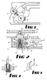
- a mirror 10 is carried by a mirror backing plate 11 (seen only in Fig. 2).
- the position of plate 11 is adjusted in the horizontal plane by a screw shaft 12 and in a vertical plane similarly by a further screw shaft 13.
- Each of a pair of gear nuts 14 is provided with resilient metal conductors 15 which constitute contact bearings, there being one contact bearing bearing against an upper surface and the other contact bearing bearing against the lower surface of each gear nut 14.
- the contact bearings are themselves formed from metal having resilient characteristics so that a good electrical contact is maintained with the gear nuts, and the contact surfaces of both the nuts and conductors are part-spherical.
- each gear nut 14 will cause inward or outward movement of its respective screw shaft 12, thereby tilting the mirror either about an horizontal or a vertical axis.
- the screw shaft 14 terminates in a ball 23 which non-rotationally engages a part-spherical socket in the mirror backing plate 11 to effect this movement.
- Each screw shaft 12 is provided with a conductive wiper 24 which is best shown in Fig. 4 and comprises a spring metal strip which bears against the crests of the threads 25 of a gear nut 14.
- the conductor B is coupled to the wiper contact 24, while conductors A and C are coupled to the respective conductor bearings 15, so that the arrangement is electrically similar to a potentiometer.
- wiper 24 receives a voltage signal from the potential gradient which is a function of the screw shaft position within the nut and thereby senses the orientation of the mirror. This signal can be fed to a micro-processor which can control operation and direction of rotation of output shaft 19 to vary orientation in accordance with stored data.
- the conductors A, B and C provide sensing means which will sense the orientation of a rear vision mirror both with respect to a vertical and an horizontal plane.
- the conductive wiper 7 can be varied in its construction or location. It can, for example, be carried by the backing plate 11 and wipe the outer surface of a nut 14.
- Fig. 5 shows a further alternative wherein a support arm 27 carries on its end a depending wire 28 within screw shaft 13, the lower end of wire 28 being an helix 29 which is engaged by the threads 25 complementary thereto.
- the helix therefore provides an alternative wiper structure to that designated 24 in Fig. 4.
- Fig. 6 is an equivalent circuit showing conductors A, B and C, and resistance R being the equivalent to the resistance of a nut 14 between conductor bearings 15.
Landscapes
- Engineering & Computer Science (AREA)
- Multimedia (AREA)
- Mechanical Engineering (AREA)
- Rear-View Mirror Devices That Are Mounted On The Exterior Of The Vehicle (AREA)
Applications Claiming Priority (2)
| Application Number | Priority Date | Filing Date | Title |
|---|---|---|---|
| AUPI171987 | 1987-05-04 | ||
| AU1719/87 | 1987-05-04 |
Publications (3)
| Publication Number | Publication Date |
|---|---|
| EP0290231A2 true EP0290231A2 (de) | 1988-11-09 |
| EP0290231A3 EP0290231A3 (en) | 1989-01-11 |
| EP0290231B1 EP0290231B1 (de) | 1990-08-08 |
Family
ID=3772145
Family Applications (1)
| Application Number | Title | Priority Date | Filing Date |
|---|---|---|---|
| EP88304021A Expired - Lifetime EP0290231B1 (de) | 1987-05-04 | 1988-05-04 | Steuereinrichtung zur Spiegelausrichtung |
Country Status (6)
| Country | Link |
|---|---|
| US (1) | US4856885A (de) |
| EP (1) | EP0290231B1 (de) |
| JP (1) | JPS6447636A (de) |
| KR (1) | KR880013736A (de) |
| ES (1) | ES2016869B3 (de) |
| NZ (1) | NZ224444A (de) |
Cited By (4)
| Publication number | Priority date | Publication date | Assignee | Title |
|---|---|---|---|---|
| WO1997003863A1 (de) * | 1995-07-21 | 1997-02-06 | Robert Bosch Gmbh | Vorrichtung zum verstellen eines kraftfahrzeugspiegels |
| WO2001020262A1 (en) * | 1999-09-16 | 2001-03-22 | Schefenacker Vision Systems Australia Pty Ltd | Sensor memory electronic circuit |
| DE19728142B4 (de) * | 1997-07-02 | 2006-04-27 | Donnelly Hohe Gmbh & Co. Kg | Spiegel-Verstellantrieb |
| CN107580567A (zh) * | 2016-05-04 | 2018-01-12 | Smr专利责任有限公司 | 用于后视显示设备的定位系统 |
Families Citing this family (20)
| Publication number | Priority date | Publication date | Assignee | Title |
|---|---|---|---|---|
| IT1216044B (it) * | 1988-03-10 | 1990-02-22 | Alfa Lancia Ind | Specchio retrovisore con supporto regolabile per autoveicoli. |
| GB9127174D0 (en) * | 1991-12-21 | 1992-02-19 | Britax Weathershields | Rear view mirror assembly for motor vehicle |
| US5363246A (en) * | 1993-05-12 | 1994-11-08 | United Technologies Automotive, Inc. | Power pack for an automotive exterior mirror assembly |
| KR100196451B1 (ko) * | 1994-01-29 | 1999-06-15 | 도시키 사이토 | 우편물 |
| US5701211A (en) * | 1995-03-31 | 1997-12-23 | United Technologies Automotive Systems, Inc. | Vehicle mirror adjustment gear train |
| US6122456A (en) * | 1996-03-12 | 2000-09-19 | Asahi Kogaku Kogyo Kabushiki Kaisha | Movement control device |
| US5959790A (en) * | 1997-01-14 | 1999-09-28 | Harman Automotive, Inc. | Breakaway mirror construction and method of assembly |
| US5926331A (en) * | 1997-01-30 | 1999-07-20 | Harman Automotive, Inc. | Power pack for controlling the angular position of a vehicle rearview mirror |
| JP3396018B2 (ja) * | 1997-03-25 | 2003-04-14 | 株式会社村上開明堂 | ミラー位置検出装置 |
| EP1020328A3 (de) * | 1999-01-11 | 2003-04-02 | Donnelly Corporation | Verstellantrieb für einen Fahrzeugspiegel |
| US6213612B1 (en) | 1999-01-11 | 2001-04-10 | Donnelly Corporation | Mirror actuator electrical connector |
| US6555222B1 (en) | 2000-01-13 | 2003-04-29 | Schefenacker Vision Systems France Sa | Reinforced polypropylene mirror assembly and process for making the same |
| WO2004009408A1 (en) * | 2002-07-19 | 2004-01-29 | Magna Donnelly North America, L.L.C. | Rear view mirror with snap connection |
| US7090363B1 (en) | 2003-02-27 | 2006-08-15 | Magna Donnelly Mirrors North America L.L.C. | Mirror actuator assembly with modular positional memory device |
| US7080914B1 (en) | 2003-02-27 | 2006-07-25 | Magna Donnelly Mirrors North America L.L.C. | Vehicular mirror with adjustable pivot connection |
| JP4217187B2 (ja) * | 2004-04-07 | 2009-01-28 | 株式会社村上開明堂 | ミラー位置検出装置 |
| JP2006096146A (ja) * | 2004-09-29 | 2006-04-13 | Murakami Corp | ミラー及び角度検出装置 |
| PL2498888T3 (pl) * | 2009-11-12 | 2015-03-31 | Lego As | Zabawkowy zestaw budowlany z urządzeniem uruchamiającym zabezpieczającym przed przeciążeniem |
| CN104590132B (zh) * | 2015-02-13 | 2017-04-26 | 宁波精成车业有限公司 | 汽车后视镜镜面驱动器双离合打滑装置 |
| TWI603539B (zh) * | 2017-01-26 | 2017-10-21 | 廖生興 | 自動式萬用插座 |
Family Cites Families (6)
| Publication number | Priority date | Publication date | Assignee | Title |
|---|---|---|---|---|
| SE449071B (sv) * | 1981-07-17 | 1987-04-06 | Hohe Kg | Backspegel for fordon |
| DE3213694A1 (de) * | 1982-04-14 | 1983-10-27 | Bernhard Mittelhaeuser | Rueckblickspiegel fuer fahrzeuge |
| US4482211A (en) * | 1982-12-13 | 1984-11-13 | Robert J. Fisher | Electrically operated remote control rearview mirror |
| NL192126C (nl) * | 1984-04-11 | 1997-02-04 | Iku Holding Montfoort Bv | Verstelinrichting met slipbeveiliging tegen overbelasting. |
| US4678295A (en) * | 1985-04-05 | 1987-07-07 | Magna International Inc | Memory positioning system for remote control rear-view mirror |
| US4770522A (en) * | 1987-11-02 | 1988-09-13 | Siegel-Robert, Inc. | Automobile mirror position sensor and adjuster assembly |
-
1988
- 1988-05-02 NZ NZ224444A patent/NZ224444A/xx unknown
- 1988-05-02 JP JP63107778A patent/JPS6447636A/ja active Pending
- 1988-05-04 EP EP88304021A patent/EP0290231B1/de not_active Expired - Lifetime
- 1988-05-04 KR KR1019880005204A patent/KR880013736A/ko not_active Withdrawn
- 1988-05-04 ES ES88304021T patent/ES2016869B3/es not_active Expired - Lifetime
- 1988-05-04 US US07/190,013 patent/US4856885A/en not_active Expired - Fee Related
Cited By (5)
| Publication number | Priority date | Publication date | Assignee | Title |
|---|---|---|---|---|
| WO1997003863A1 (de) * | 1995-07-21 | 1997-02-06 | Robert Bosch Gmbh | Vorrichtung zum verstellen eines kraftfahrzeugspiegels |
| DE19728142B4 (de) * | 1997-07-02 | 2006-04-27 | Donnelly Hohe Gmbh & Co. Kg | Spiegel-Verstellantrieb |
| WO2001020262A1 (en) * | 1999-09-16 | 2001-03-22 | Schefenacker Vision Systems Australia Pty Ltd | Sensor memory electronic circuit |
| CN107580567A (zh) * | 2016-05-04 | 2018-01-12 | Smr专利责任有限公司 | 用于后视显示设备的定位系统 |
| CN107580567B (zh) * | 2016-05-04 | 2019-11-19 | Smr专利责任有限公司 | 用于后视显示设备的定位系统 |
Also Published As
| Publication number | Publication date |
|---|---|
| NZ224444A (en) | 1990-03-27 |
| JPS6447636A (en) | 1989-02-22 |
| KR880013736A (ko) | 1988-12-21 |
| US4856885A (en) | 1989-08-15 |
| ES2016869B3 (es) | 1990-12-01 |
| EP0290231B1 (de) | 1990-08-08 |
| EP0290231A3 (en) | 1989-01-11 |
Similar Documents
| Publication | Publication Date | Title |
|---|---|---|
| US4856885A (en) | Mirror orientation control means | |
| CN1050574C (zh) | 改进的双转动后视镜组件 | |
| US5598207A (en) | Camera pointing mechanism using proximate magnetic sensing | |
| US6547404B2 (en) | Digital electrochromic mirror system | |
| EP0274848B1 (de) | Steuerungseinrichtung für Kraftfahrzeugrückspiegel | |
| EP0321716A1 (de) | Antriebseinheit für elektrisch fernbedienbaren Spiegel | |
| EP0944496B1 (de) | Spiegelanordnung mit reibungsgetriebe | |
| US4374348A (en) | Wiper device | |
| AU600125B2 (en) | Mirror orientation control means | |
| US4295708A (en) | Electro-mechanically rotatable mirror | |
| JPS5863532A (ja) | ヘツドランプ傾動装置 | |
| US4824232A (en) | Drive system with resilient yieldable biased actuator shaft for electric rear view mirror | |
| EP1063128A2 (de) | Kraftfahrzeug- Aussenrückblickspiegel | |
| EP0463563A1 (de) | Elektrisch fernbedienbarer Rückspiegel | |
| CN2040461U (zh) | 用于车辆的外后视镜组件 | |
| JPH0380660B2 (de) | ||
| US3234507A (en) | Curb distance indicator | |
| WO1992010063A1 (en) | Surveillance systems | |
| EP0631898B1 (de) | Elektronische Anzeigeeinheit | |
| EP0265973A1 (de) | Einstellvorrichtung für Rüchblickspiegel | |
| CN217654466U (zh) | 一种具有双齿轮结构的后视镜传感器 | |
| JPH0240529B2 (de) | ||
| JPS59230839A (ja) | 電動式バツクミラ−の角度検出装置 | |
| JP2500134Y2 (ja) | 自動車用前照灯照射角調整装置の角度検出機構 | |
| JPH0729017Y2 (ja) | 自動車用前照灯照射角調整装置の角度検出機構 |
Legal Events
| Date | Code | Title | Description |
|---|---|---|---|
| PUAI | Public reference made under article 153(3) epc to a published international application that has entered the european phase |
Free format text: ORIGINAL CODE: 0009012 |
|
| AK | Designated contracting states |
Kind code of ref document: A2 Designated state(s): DE ES FR GB |
|
| PUAL | Search report despatched |
Free format text: ORIGINAL CODE: 0009013 |
|
| AK | Designated contracting states |
Kind code of ref document: A3 Designated state(s): DE ES FR GB |
|
| 17P | Request for examination filed |
Effective date: 19890513 |
|
| 17Q | First examination report despatched |
Effective date: 19890927 |
|
| GRAA | (expected) grant |
Free format text: ORIGINAL CODE: 0009210 |
|
| AK | Designated contracting states |
Kind code of ref document: B1 Designated state(s): DE ES FR GB |
|
| REF | Corresponds to: |
Ref document number: 3860416 Country of ref document: DE Date of ref document: 19900913 |
|
| ET | Fr: translation filed | ||
| PG25 | Lapsed in a contracting state [announced via postgrant information from national office to epo] |
Ref country code: ES Free format text: LAPSE BECAUSE OF NON-PAYMENT OF DUE FEES Effective date: 19910506 |
|
| PLBE | No opposition filed within time limit |
Free format text: ORIGINAL CODE: 0009261 |
|
| STAA | Information on the status of an ep patent application or granted ep patent |
Free format text: STATUS: NO OPPOSITION FILED WITHIN TIME LIMIT |
|
| 26N | No opposition filed | ||
| PG25 | Lapsed in a contracting state [announced via postgrant information from national office to epo] |
Ref country code: FR Effective date: 19920131 |
|
| PG25 | Lapsed in a contracting state [announced via postgrant information from national office to epo] |
Ref country code: DE Effective date: 19920303 |
|
| REG | Reference to a national code |
Ref country code: FR Ref legal event code: ST |
|
| PG25 | Lapsed in a contracting state [announced via postgrant information from national office to epo] |
Ref country code: GB Effective date: 19920504 |
|
| GBPC | Gb: european patent ceased through non-payment of renewal fee |
Effective date: 19920504 |
|
| REG | Reference to a national code |
Ref country code: ES Ref legal event code: FD2A Effective date: 19990405 |